This page contains terminology and definitions for the lighthouse system to make it easier to understand and discuss algorithms and code. Our definitions probably do not match the ones used by other software packages, but we find these suitable for our setup.
Reference frames
There are a number of different reference frames (or coordinate systems) used.
Global reference frame
The global coordinate system is fixed in the room and shared by all parts of the system. This system is used for absolute position references in set points and the kalman estimator.
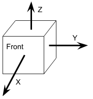
Crazyflie reference frame
The Crazyflie reference frame is defined with the X-axis pointing forward, the Y-axis pointing left when seen from behind and the Z-axis pointing upwards.
Base station reference frame
The base station coordinate system is defined as
- X-axis pointing forward through the glass
- Y-axis pointing right, when the base station is seen from the front.
- Z-axis pointing up (away from the screw mount)
Rotor reference frame
There is one (LH2) or two rotors (LH1) in a base station. Each rotor is rotating around an axis of rotation, . We define a coordinate system for the rotor where the Z-axis points along and the X-axis is the same as the X-axis of the base station.
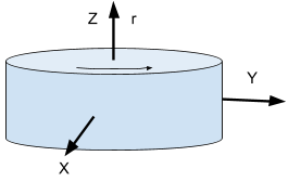
The axis of rotation is defined such that when is pointing towards you, the drum is spinning counterclockwise.
Geometry data
The geometry data (position and rotation matrix ) describes the pose of a base station in the global coordinate system such that a point in the base station reference frame is transformed to the global reference frame by .
Rotors
In relation to the base station reference frame we have
| System type | rotor | |
|---|---|---|
| LH 1 | horizontal sweep (left to right seen from the front) | |
| LH 1 | vertical sweep (down to up seen from the front) | |
| LH 2 | horizontal sweep (left to right seen from the front) |
The coordinate systems for the horizontal LH1 rotor and the LH2 rotor are identical to the base station reference frame.
Rotation angle
Rotation angle is forward, along the X axis in the rotor (and base station) reference frame.
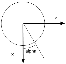
Note: In LH2 the two light planes are offset from each other on the rotor by 120 degrees, but this offset is compensated for in the decoding part of the firmware. For a sensor placed along the X-axis, the measured for both light planes.
Light plane tilt
There is a lens on the rotor spreading light in the form of a plane, rotating with the rotor. In LH1 the plane is oriented along the axis of rotation, sweeping the room when the rotor spins, while LH2 has two light planes that are tilted by an angle . is defined such that the plane is rotated counterclockwise with increasing , seen from the front of the base station ().

In the general form we have no tilt for the rotors of LH1, in LH2 the planes are tilted 30 degrees.
| System type | rotor / light plane | |
|---|---|---|
| LH 1 | horizontal sweep (left to right seen from the front) | 0 |
| LH 1 | vertical sweep (down to up seen from the front) | 0 |
| LH 2 | horizontal sweep, first light plane | |
| LH 2 | horizontal sweep, second light plane |