Crazyradio 2.0 implements a USB and radio protocol that is a strict superset of the Crazyradio PA USB protocol. When using this protocol Crazyradio 2.0 is compatible with all software that supports Crazyradio PA in the context of controlling a Crazyflie.
The radio communication is done using the Nordic "Enhanced ShockBurst™" packet protocol in PTX mode with acknowledge. Variable sized packet, from 1 to 32 bytes, can be send and acknowledged by the copter. The acknowledgement packet can contain a payload from 0 to 32 Bytes. In sniffer mode, the radio supports packets up to 63 bytes (the full 6-bit length field range).
This page documents the protocol used in version 5.0 of the Crazyradio 2.0 firmware.
Radio configuration
Crazyradio is configured in PTX mode. It can communicate with Nordic chips compatible with the nrf24L family (at least nrf24L01p, nRF51 and nRF52 tested). In order to communicate with the Crazyradio the target has to be configure correctly:
- PRX mode
- One active pipe with the address configured in the Crazyradio dongle, by default it is 0xE7E7E7E7E7
- 5 byte address
- Dynamic payload length enable
- Payload with ack enable
The Crazyflie is already configured that way. The relevant source code can be seen in radiolink.c.
USB protocol
The USB devices has the VID/PID couple 0x1915/0x7777.
| EP0 | Control | Control endpoint. Used to configure the dongle |
| EP1IN/OUT | Bulk | Data endpoints. Used to send and receive radio packets |
Data transfer
When the radio dongle is configured to use PTX (emitter) mode it sends a packet to the copter and waits for the acknowledge. The acknowledge can contain a payload which is the mean to receive data. If the auto acknowledge is disabled there is no IN transaction.
To send a packet, the following sequence must be followed:
- Send the packet to EP1_OUT. Its length should be between 1 to 32 Bytes in normal mode (up to 63 bytes in sniffer mode). If Inline mode is enabled, the packet payload is prepended by radio settings (see Inline setting mode)
- Read the ACK from EP1_IN. The first byte is the transfer status and the following bytes are the content of the ACK payload, if any.
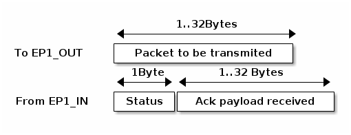
The status byte contains flags indicating the quality of the link:
| Status Bit | Role |
|---|---|
| 4..7 | Number of retransmission |
| 2..3 | Reserved |
| 1 | Power detector |
| 0 | ACK received |
Dongle configuration and functions summary
Crazyradio vendor requests summary:
| bmRequestType | bRequest | wValue | wIndex | wLength | data |
|---|---|---|---|---|---|
| 0x40 | SET_RADIO_CHANNEL (0x01) | channel | Zero | Zero | None |
| 0x40 | SET_RADIO_ADDRESS (0x02) | Zero | Zero | 5 | Address |
| 0x40 | SET_DATA_RATE (0x03) | Data rate | Zero | Zero | None |
| 0x40 | SET_RADIO_POWER (0x04) | Power | Zero | Zero | None |
| 0x40 | SET_RADIO_ARD (0x05) | ARD | Zero | Zero | None |
| 0x40 | SET_RADIO_ARC (0x06) | ARC | Zero | Zero | None |
| 0x40 | ACK_ENABLE (0x10) | Active | Zero | Zero | None |
| 0x40 | SET_CONT_CARRIER (0x20) | Active | Zero | Zero | None |
| 0x40 | START_SCAN_CHANNELS (0x21) | Start | Stop | Length | Packet |
| 0xC0 | GET_SCAN_CHANNELS (0x21) | Zero | Zero | 63 | Result |
| 0x40 | SET_INLINE_MODE (0x23) | Mode | Zero | Zero | None |
| 0x40 | SET_RADIO_MODE (0x24) | Mode (0-1) | Zero | Zero | None |
| 0x40 | SET_SNIFFER_ADDRESS (0x25) | Pipe (0-1) | Zero | 5 | Address |
| 0xC0 | GET_SNIFFER_DROP_COUNT (0x26) | Zero | Zero | 4 | uint32_t LE |
| 0x40 | SET_PACKET_LOSS_SIMULATION (0x30) | Zero | Zero | 2 | [packet_loss_percent: u8, ack_loss_percent:u8] |
| 0x40 | LAUNCH_BOOTLOADER (0xFF) | Zero | Zero | Zero | None |
Set radio channel
| bmRequestType | bRequest | wValue | wIndex | wLength | data |
|---|---|---|---|---|---|
| 0x40 | SET_RADIO_CHANNEL (0x01) | channel | Zero | Zero | None |
The nRF24LU1 chip provides 126 Channels of 1MHz from 2400MHz to 2525MHz. The channel parameter shall be between 0 and 125 (if not, the command will be ignored).
The radio channel is set as soon as the USB setup transaction is completed, which takes about 1ms. The new frequency is going to be used for the following transferred packets. The default value for the radio channel is 2.
Note: This command disables inline mode if it was previously enabled. —
Set radio address
| bmRequestType | bRequest | wValue | wIndex | wLength | data |
|---|---|---|---|---|---|
| 0x40 | SET_RADIO_ADDRESS (0x02) | Zero | Zero | 5 | Address |
The packet sent by the radio contains a 5 bytes address. The same address must be configured in the receiver for the communication to work.
The address must follow the requirement of section 6.4.3.2 of the nRF24LU1 documentation:
Addresses where the level shifts only one time (that is, 000FFFFFFF) can often be detected in noise and can give a false detection, which may give a raised Packet-Error-Rate. Addresses as a continuation of the preamble (hi-low toggling) raises the Packet-Error-Rate.
The default address is 0xE7E7E7E7E7.
Note: This command disables inline mode if it was previously enabled. —
Set data rate
| bmRequestType | bRequest | wValue | wIndex | wLength | data |
|---|---|---|---|---|---|
| 0x40 | SET_DATA_RATE (0x03) | Data rate | Zero | Zero | None |
Possible values for the data rate:
| Value Radio data rate |
|---|
| 0 250Kbps |
| 1 1MBps |
| 2 2Mbps (Default) |
Note: This command disables inline mode if it was previously enabled. —
Set radio power
| bmRequestType | bRequest | wValue | wIndex | wLength | data |
|---|---|---|---|---|---|
| 0x40 | SET_RADIO_POWER (0x04) | Power | Zero | Zero | None |
Sets the radio amplifier output power. Possible values:
| Value | Power |
|---|---|
| 0 | -18dBm |
| 1 | -12dBm |
| 2 | -6dBm |
| 3 | 0dBm |
Configure auto retry (ARD/ARC)
| bmRequestType | bRequest | wValue | wIndex | wLength | data |
|---|---|---|---|---|---|
| 0x40 | SET_RADIO_ARD (0x05) | ARD | Zero | Zero | None |
| 0x40 | SET_RADIO_ARC (0x06) | ARC | Zero | Zero | None |
After sending a packet the radio automatically waits for an acknowledge. ARD and ARC permit to configure the delay the radio waits for the acknowledge and the number of times the transfer will be retried in case the acknowledge is not received in that delay.
The delay ARD depends on the length, in seconds, of the ACK packet. This depends on the data rate and the payload length contained in the ACK packet. The ARD can be configured either by steps of 250us or by ACK payload length. If the ACK payload length is configured, the time will be recalculated automatically even if the data rate is changed. To set the ACK payload length the bit 7 of ARD must be set (length | 0x80).
Possible values for ARD:
| Value | ARD wait time |
|---|---|
| 0x00 | 250us |
| 0x01 | 500us |
| ... | ... |
| 0x0F | 4000us |
| Value | ACK payload length |
| 0x80 | 0Byte |
| 0x81 | 1Byte |
| ... | ... |
| 0xA0 | 32Bytes |
ARC configures the number of times the radio will retry a transfer if the ACK has not been received, it can be set from 0 to 15.
By default ARD=32Bytes (0xA0) and ARC=3.
Auto ACK configuration
| bmRequestType | bRequest | wValue | wIndex | wLength | data |
|---|---|---|---|---|---|
| 0x40 | ACK_ENABLE (0x10) | Active | Zero | Zero | None |
By default, the Crazyradio is configured with auto ACK enabled. This means that after transmitting a packet, the radio waits for an acknowledge from the receiver. This setting permits to deactivate waiting for the ACK packet so that the packet will be sent only one time and there is no guarantee that it has been correctly received.
| Active values | Meaning |
|---|---|
| 0 | Auto ACK deactivated |
| Not 0 | Auto ACK enable (default) |
Note: This command disables inline mode if it was previously enabled. —
Continuous carrier mode
| bmRequestType | bRequest | wValue | wIndex | wLength | data |
|---|---|---|---|---|---|
| 0x40 | SET_CONT_CARRIER (0x20) | Active | Zero | Zero | None |
The nRF24L radio chip provides a test mode in which a continuous non-modulated sine wave is emitted. This permits, among other things, to test the quality of the RF elements of the board. When this mode is activated the radio dongle does not transmit any packets.
While the continuous carrier mode is active, it is possible to set channel and power to change the frequency and power of the emitted wave.
| Active values | Meaning |
|---|---|
| 0 | Dongle working normally (default) |
| Not 0 | Dongle in continuous carrier mode |
Channels scanning
This function is implemented in Crazyradio version 0.5 and over.
| bmRequestType | bRequest | wValue | wIndex | wLength | data |
|---|---|---|---|---|---|
| 0x40 | START_SCAN_CHANNELS (0x21) | Start | Stop | Length | Packet |
| 0xC0 | GET_SCAN_CHANNELS (0x21) | Zero | Zero | 64 | Result |
Scan a range of channels and compile a list of channel from which an ACK has been received. The command START_SCAN_CHANNELS should be executed first with start being the first scanned channel and stop the last one. Those should be within 0 to 125. The data is the packet payload sent on each channel, it should be at least one byte long.
All parameters, except the channel, are used unmodified during the scan. If the data rate is set to 2MBPs the scan is done every second channel. To get the list of channels that answered, GET_SCANN_CHANNELS should be called just after a scan. Up to 63 bytes are returned corresponding to up to 63 channels on which the packet was acknowledged.
Note
After scanning, the channel will be set to the last scanned channel.
Warning On some platform, an empty scan will return a buffer of 64 bytes. This is though to be a USB host implementation bug, see ticket #9 in the Crazyradio firmware project. If a buffer of more than 63 bytes is returned, it means that no channel have been received.
Inline settings mode
| bmRequestType | bRequest | wValue | wIndex | wLength | data |
|---|---|---|---|---|---|
| 0x40 | SET_INLINE_MODE (0x23) | Mode | Zero | Zero | None |
This mode allows sending radio configuration together with packet payload on the OUT endpoint. This makes the communication with multiple PRX much more efficient!
Two inline mode exists, one that returns the same information as the regular mode and one that adds received RSSI value for each received packet in the IN endpoint header.
| Mode values | Meaning |
|---|---|
| 0 | Inline mode deactivated (default) |
| 1 | Inline mode enabled |
| 2 | Inline mode with RSSI enabled |
| … | Reserved, STALL the setup phase |
When enabled, the data format on the OUT endpoint becomes:
OUT endpoint format (host to device):
| Byte position | Length (bytes) | Description |
|---|---|---|
| 0 | 1 | Total length (including this header) |
| 1 | 1 | Datarate (bits 0-1: 0=250kbps, 1=1Mbps, 2=2Mbps) Ack enabled (bit 4: 0=disabled, 1=enabled) |
| 2 | 1 | Radio channel (0-100) |
| 3-7 | 5 | Radio address (5 bytes) |
| 8+ | 0-32 | Radio packet payload |
IN endpoint format for inline mode (1) (device to host):
After sending a packet in inline mode, the response format on the IN endpoint is:
| Byte position | Length (bytes) | Description |
|---|---|---|
| 0 | 1 | Total length (including this header) |
| 1 | 1 | Ack received (bit 0: 0=no ack, 1=ack received) RSSI < -64dBm (bit 1: 0=strong signal, 1=weak signal) Invalid settings (bit 2: 0=valid, 1=invalid settings) Retransmission count (bits 4-7: 0-15) |
| 2+ | 0-32 | ACK payload data (if any) |
IN endpoint format for inline mode with RSSI (2) (device to host):
After sending a packet in inline mode with RSSI, the response format on the IN endpoint is:
| Byte position | Length (bytes) | Description |
|---|---|---|
| 0 | 1 | Total length (including this header) |
| 1 | 1 | Ack received (bit 0: 0=no ack, 1=ack received) RSSI < -64dBm (bit 1: 0=strong signal, 1=weak signal) Invalid settings (bit 2: 0=valid, 1=invalid settings) Retransmission count (bits 4-7: 0-15) |
| 2 | 1 | Received packet RSSI in inverted dBm. Value of 60 means -60dBm. Value is only valid for an acked packet. |
| 3+ | 0-32 | ACK payload data (if any) |
Settings validation:
Invalid settings that are not handled by Crazyradio 2 (causing invalid_settings flag to be set):
- Datarate value of 0 (250kbps is not handled by Crazyradio 2.0)
- Channel value greater than 100
The settings are applied in the same way as if they were set using setup commands: they replace any other settings that have been made before and will stick to be used by future packets if inline mode is disabled.
Sniffer mode
| bmRequestType | bRequest | wValue | wIndex | wLength | data |
|---|---|---|---|---|---|
| 0x40 | SET_RADIO_MODE (0x24) | Mode | Zero | Zero | None |
| 0x40 | SET_SNIFFER_ADDRESS (0x25) | Pipe (0-1) | Zero | 5 | Address |
| 0xC0 | GET_SNIFFER_DROP_COUNT (0x26) | Zero | Zero | 4 | uint32_t LE |
Sniffer mode puts the radio in continuous RX mode, passively listening for ESB packets on the configured channel, datarate, and address(es). This is useful for debugging and monitoring Crazyflie communications.
Entering sniffer mode:
- Configure channel, datarate, and address using the standard commands (SET_RADIO_CHANNEL, SET_DATA_RATE, SET_RADIO_ADDRESS)
- Optionally set a second address on pipe 1 using SET_SNIFFER_ADDRESS with wValue=1
- Send SET_RADIO_MODE with wValue=1 to enter sniffer mode
Exiting sniffer mode:
Send SET_RADIO_MODE with wValue=0. Normal TX/ACK operation is restored.
Detecting sniffer support:
Sending SET_RADIO_MODE with any unsupported wValue (>= 2) will cause a USB STALL, which can be used to detect whether the firmware supports sniffer mode without checking the firmware version.
| Mode values | Meaning |
|---|---|
| 0 | Normal mode (default) |
| 1 | Sniffer mode (continuous RX) |
SET_SNIFFER_ADDRESS:
Sets the radio address for sniffer pipe 0 or pipe 1. Pipe 0 can also be set using the existing SET_RADIO_ADDRESS command before entering sniffer mode.
| wValue | Meaning |
|---|---|
| 0 | Set pipe 0 address (same as SET_RADIO_ADDRESS) |
| 1 | Set pipe 1 address |
GET_SNIFFER_DROP_COUNT:
Returns the number of packets dropped due to queue overflow since the last time sniffer mode was entered (as a 4-byte little-endian uint32_t).
IN endpoint sniffer packet format (device to host):
While in sniffer mode, received packets are streamed on the IN endpoint with the following format:
| Byte position | Length (bytes) | Description |
|---|---|---|
| 0 | 1 | Total length (7 + payload length) |
| 1 | 1 | RSSI in inverted dBm (e.g. 60 = -60 dBm) |
| 2 | 1 | Pipe index (0 or 1) |
| 3-6 | 4 | Timestamp in microseconds (uint32_t LE, wraps ~71 min) |
| 7+ | 0-63 | ESB packet payload |
The total USB transfer size is 7 + payload length (range: 7 to 70 bytes). When the total length exceeds 64 bytes (the USB bulk max packet size), the device automatically splits the transfer across multiple USB packets. When the total length is exactly 64 bytes (57-byte payload), the device sends a zero-length packet (ZLP) to terminate the transfer.
OUT endpoint broadcast TX (host to device):
While in sniffer mode, sending data on the OUT endpoint transmits it as a no-ack (broadcast) ESB packet using the current channel and datarate. The first 5 bytes specify the destination address, followed by the raw ESB payload (1-63 bytes):
| Offset | Size (bytes) | Description |
|---|---|---|
| 0-4 | 5 | Destination address (5 bytes) |
| 5+ | 1-63 | ESB packet payload |
The total USB transfer size is 5 + payload length (range: 6 to 68 bytes). When the total exceeds 64 bytes (the USB bulk max packet size), the host must split the transfer across multiple USB packets. When the total is exactly 64 bytes (59-byte payload), the host must send a ZLP to terminate the transfer. Most USB libraries (e.g. libusb) handle this automatically for bulk endpoints.
No response is sent on the IN endpoint.
During TX (~1ms), the radio briefly leaves RX mode. Incoming packets during this window will be missed (not counted in the drop counter).
The blue LED is on while sniffer mode is active. The green LED pulses briefly for each received or transmitted packet.
Packet loss simulation
| bmRequestType | bRequest | wValue | wIndex | wLength | data |
|---|---|---|---|---|---|
| 0x40 | SET_PACKET_LOSS_SIMULATION (0x30) | Zero | Zero | 2 | [packet_loss_percent: u8, ack_loss_percent:u8] |
Crazyradio 2.0 has the capability to simulate packet loss. This is useful for working with and debuging communication protocols.
The packet loss percentage, makes the radio drop a certain percentage of packet before sending them to the radio. This means the receiver will not receive the packet.
The Ack loss percentage drops a certain percentage of ack packets. This means that the receiver will receive the packet, send the ack but the ack packet might be dropped by Crazyradio and reported as lost.
Both case will look the same on the PC side: the packet is reported as not acked.
Launch bootloader
| bmRequestType | bRequest | wValue | wIndex | wLength | data |
|---|---|---|---|---|---|
| 0x40 | LAUNCH_BOOTLOADER (0xFF) | Zero | Zero | Zero | None |
This command is used to launch the Nordic semiconductor USB bootloader. After sending this command, a USB reset shall be emitted which will trigger the dongle to start the bootloader. After sending this command, the Dongle is only waiting for a USB reset which means that any other commands or data will be ignored.
The bootloader is pre-loaded by Nordic Semi. in the nRF24LU1 chip at the address 0x7800. The Crazyradio firmware will jump to it when the sequence LAUCH_BOOTLOADER followed by a USB reset is executed. The bootloader will appear at VID/PID of 0x1915/0x0101. See nRF24LU1 datasheet for the bootloader documentation.
A PC client for the bootloader is part of the Crazyflie ground station program.
Radio protocol
The Crazyradio dongle is currently only operating in PTX mode. To get a downlink from the copter the ACK payload is used, which means that data are received only when data are sent. In the case of Crazyflie, to have bidirectional communication even when no data is send, a null packet (0xff) is sent periodically to pull the downlink data stream.
For Crazyflie the communication protocol is described in Communication protocol Overview.