
Add lights to your Crazyflie 2.x
Light up the dark with custom patterns using the Crazyflie 2.x LED-ring expansion deck.
How it works
Light up the dark with custom patterns using the Crazyflie® 2.x LED-ring expansion board. Featuring 12 strong RGB LEDs facing downwards, you can create custom patterns in firmware that you control from your computer. Two additional strong front facing LEDs that can be switched on and off, act as headlights.
NOTE: This deck is not compatible with the Crazyflie 2.1 Brushless by default. You will need to perform a software modification.
Specifications
Features
- DC-DC step-up/down gives stable LED light independent of battery voltage
- Create custom patterns using the Crazyflie 2.X firmware
- 12 RGB LED modules facing downwards
- 2 strong LEDs facing forward
- Automatic detection of expansion board using 1-wire memory
Mechanical specifications
- Weight: 3.3g
- Size (WxHxD): 33x33x5.5mm
- Designed for mounting under the Crazyflie facing downwards
Electrical specification
- DC-DC step-up/down gives up to 1A at 3.8V from input between 2-5.5V
- 12 independently addressable RGB LED modules facing downwards (W2812B)
- 2 strong white LEDs facing forward, emitting more than 1800 mcd
- 1-wire memory for automatic expansion board detection
- Typical power consumption: 330mA @ 5.0V and 680mA @ 3.0V
Compatibility
Usage
The different LED patterns can selected from CFclient’s Flight tab.
Once you have selected the right pattern, go ahead and fly!
Development
Firmware implementation
All the LED-ring deck’s effects are implemented in the led-ring driver.
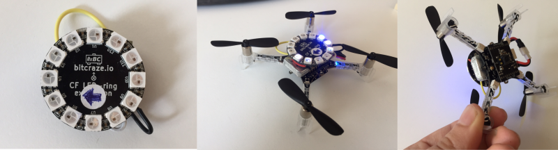
Hardware Hack: LED-ring on top
In case you want to have the LED-ring on top in combination with the Flow deck V2 !
What do you need for this:
- A soldering station with solder
- Couple of wires
- Battery holder deck
- LED deck
- Hotglue or tape
What we are essentially doing, is that we are flipping the pin-layout of the LED deck so that it is compatible to be put on the top of the Crazyflie.
The image below shows how you should solder the wiring. The Gnd (ground), IO2, OW (deck single wire memory), and VCOM (power supply). Please check out this page to familiarize yourself with the pin-outs of the expansion decks.
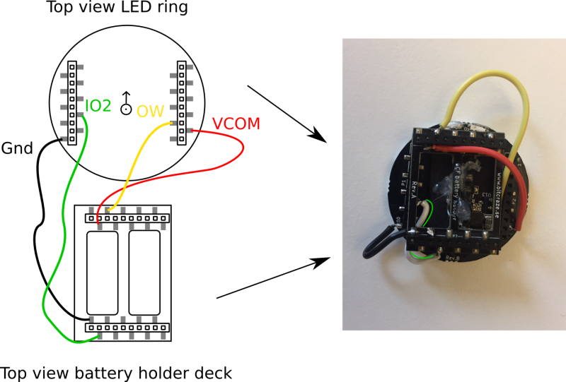
We did not connect IO3 on purpose since the Flow deck v2 is already using this, or else the LED deck and Flow deck V2 will conflict with each other’s communication with the Crazyflie. However, the LED deck should work as well without the IO3 connected.
The battery holder deck can be glued on the LED-deck or attached with some tape. The wiring and soldering are done a bit crude for now to clearly show how to do this, however if you would like the wiring not to be shown as clearly as it is here, this should be easy to fix with thinner wires and basic soldering skills. =)
Please pay attention to that the orientation of the LED deck is now different. We put the battery holder on the side to prevent any connections to short with the LED deck, but now you would need to indicate the new ‘front’ of the LED deck. On the bottom left picture we show it with a sticker.
The final step is to modify the firmware. The GPIO pins used by a deck are registered in the deck driver to enable the system to detect conflicts. As the LED-ring is not using IO3 in this configuration,
it should be removed from the deck driver to enable it to be used with the Flow deck (that is using IO3). Open the ledring12.c file and modify this line in the deck driver by removing | DECK_USING_IO_3. Re-compile the firmware and flash it to the Crazyflie (see the Getting started with development).
We tested the converted LED deck with the Flow deck V2 with the CFclient and we are still receiving the values and parameters from both the deck drivers.
Resources
- Start here
- Development overview
- FAQ
- Getting help
- Expansion decks of the Crazyflie 2.x
- Datasheet
- Schematics
If you have any further questions please contact support@bitcraze.io