
Development and test of hardware made simple
Easily connect to the Crazyflie 2.x expansion port when developing new hardware.
How it works
Test and develop new hardware designs easily without soldering by using the breakout expansion board. Just build the circuit on a breadboard and attach the Crazyflie® 2.x to it. The board has all the 20 expansion connector pins available as well as a footprint where a 1-wire memory could be soldered to make the board auto-detectable by the firmware.
Specifications
Features
- SOT-23 footprint for 1-wire memory used for automatic detection (not mounted)
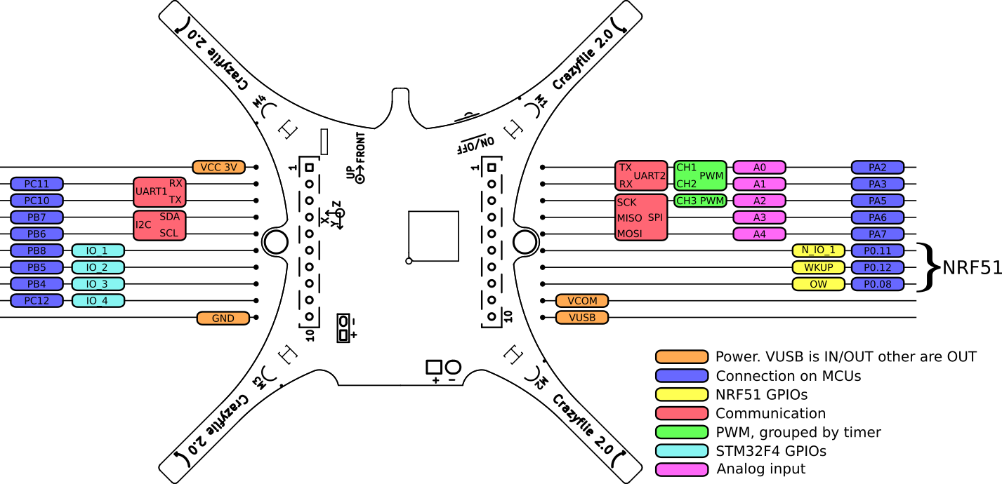
- All 20 pins in the deck expansion port available
- 2.54mm header that fits a breadboard (not included)
- Screen-print showing all signal names
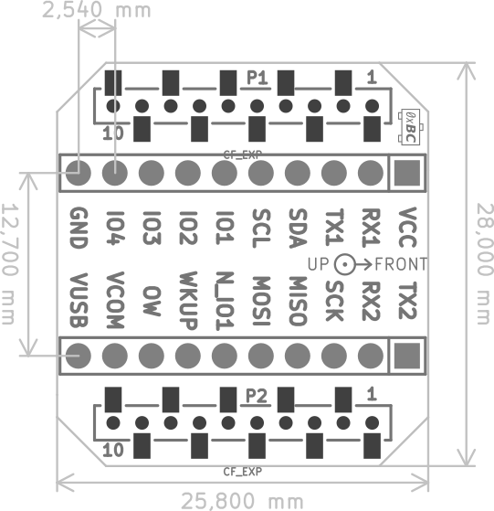
Mechanical specifications
- Weight: 1.5 g
- Size (WxHxD): 27x28x4mm
- Designed for mounting above or under the Crazyflie 2.X
Mechanical drawing
Electrical specification
Compatibility
Works with the Crazyflie 2.x
Usage
The deck is designed to be soldered to 100mil breadboard or prototyping board. The aim is to ease prototyping by connecting breadboard circuits to Crazyflie 2.0 but it can also be used to make a bigger system using Crazyflie 2.0 as a component.
The deck has all the 20 expansion connector points directly available with a 2.54 mm spacing (100 mil) to make it easy to connect standard pin headers (not included). By mounting the deck under a Crazyflie and soldering pin headers downwards, the Crazyflie can be mounted on a breadboard for easy hardware prototyping.
The breakout board is also very useful to measure signals, for example with an oscilloscope.
Resources
If you have any further questions please contact support@bitcraze.io