We built a small drone for people who want to understand how things fly. The community took it considerably further than that. The citations keep arriving from directions we didn’t anticipate. Spacecraft dynamics. Tactile human-swarm interaction. Onboard deep learning. Mapping algorithms that fit inside a nano-drone’s compute budget. The platform’s combination of openness, known dynamics, repeatable behavior, and low replacement cost turns out to be useful for a wider set of problems than any single team could have imagined building for.
What follows is by no means a comprehensive survey, but rather a selection of research areas where the Crazyflie has found a home, each illustrated with recent work. We find it genuinely interesting that the same hardware can be useful across this range, and we hope it gives other researchers a sense of what is possible.
1. Decentralized Multi-Agent Coordination and Swarm Control
Multi-agent coordination is probably the research area most closely associated with the Crazyflie, and for good reason. The platform’s light weight, predictable dynamics, and relatively low cost per unit make it practical to run experiments with enough agents to observe emergent swarm behavior, rather than just simulating it. A lab can field a meaningful swarm without the capital outlay that larger platforms would require.
Recent work has pushed this in some interesting directions. Decentralized approaches, where each agent makes decisions based on local information rather than a central planner, are particularly well-served by a platform where individual failures don’t cascade into catastrophic system loss. Research on collision avoidance, formation control, and consensus algorithms benefits from hardware that can absorb the crashes that inevitably happen when you are testing novel coordination strategies.
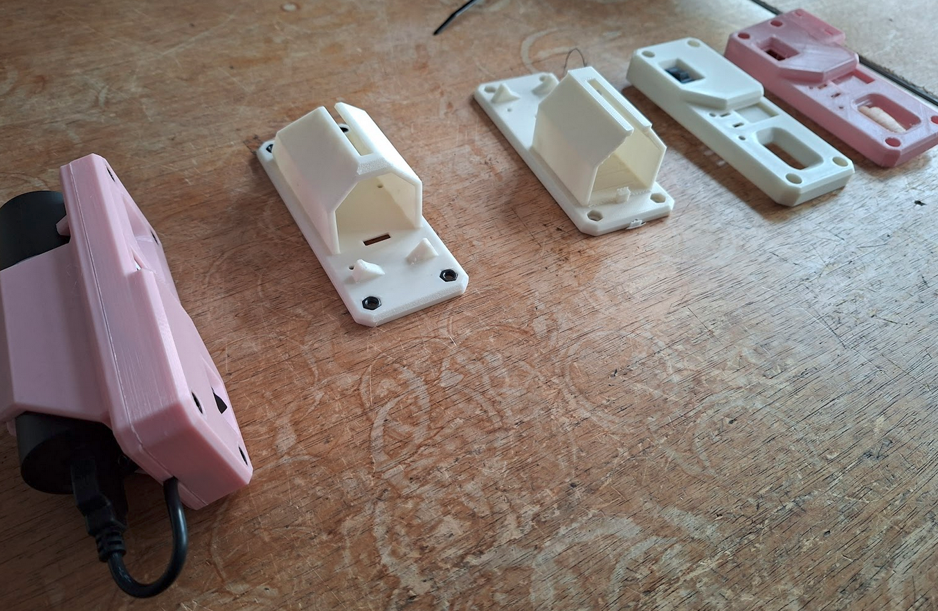
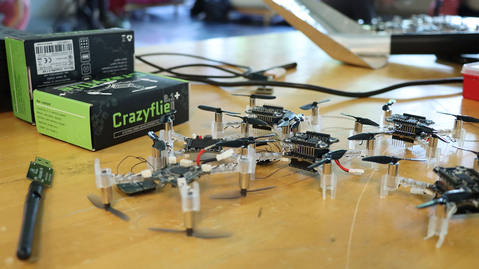
See “Design and Implementation of EPM Based Modular Micro-UAVs for Autonomous Midair Docking” IEEE paper (11248819) for an example of custom hardware extending with the Crazyflie.
The ROS 2 ecosystem around the Crazyflie has matured considerably, with frameworks like Crazyswarm2 enabling standardized multi-drone experiments that other labs can replicate. The reproducibility this enables is meaningful: a coordination result demonstrated on Crazyflies in one lab is demonstrable in another (see “CrazyChoir: Flying Swarms of Crazyflie Quadrotors in ROS 2” (arXiv)).
2. Onboard AI and Edge Inference at Nano Scale
What can you fit inside a couple of dozen grams grams and still have compute left over for intelligence? Quite a lot, it turns out, especially when researchers are motivated to find out. The AI Deck, which adds a GAP8 system-on-chip with a camera and Wi-Fi, opened a wave of work on fully onboard perception and inference pipelines on nano-UAVs.
Researchers at ETH Zurich demonstrated autonomous visual navigation along a 113-meter previously unseen indoor path using a convolutional neural networkl (CNN) running at 18 Hz on the GAP8, without any external computation (see “An Open Source and Open Hardware Deep Learning-powered Visual Navigation Engine for Autonomous Nano-UAVs” (arXiv)
More recently, work using custom expansion decks with the GAP9 processor has enabled onboard SLAM and scan-matching at take-off weights around 46 grams, showing that the platform’s expansion architecture makes it a meaningful target even as compute capabilities grow. See “Ultra-Lightweight Collaborative Mapping for Robot Swarms” (arXiv).
The Crazyflie’s transparent hardware design is important here: researchers can build custom decks, verify the power budget, and integrate new silicon without waiting for a vendor to offer an approved configuration.
3. Spacecraft and Orbital Dynamics Simulation
Researchers at the University of Houston, in collaboration with the US Air Force Research Laboratory, used Crazyflie drones to simulate the relative motion dynamics of spacecraft in formation, specifically the Clohessy-Wiltshire equations that describe how objects move relative to each other in near-circular orbit.
The reasoning is practical: testing spacecraft autonomy on-orbit is expensive and high-risk. Ground-based testbeds using air bearings exist, but are complex and space-intensive. A small fleet of Crazyflies, running scaled versions of orbital trajectories in an indoor lab, offers a much cheaper and more accessible way to validate formation-flying control laws and neural network guidance systems before committing to hardware that will be launched into space.
The paper notes exactly why the Crazyflie was chosen: it is affordable, open source, readily available, and the expansion deck ecosystem provides positioning, sensing, and even AI capabilities that can be configured to match a specific experimental requirement (see “Testing Spacecraft Formation Flying with Crazyflie Drones as Satellite Surrogates” (IEEE)).
4. Reinforcement Learning: From Simulation to Real Hardware
Reinforcement learning (RL) for drone control has been a thriving research area for years, but the gap between simulation and physical hardware remains a hard problem to close. The Crazyflie’s well-documented dynamics, consistent manufacturing, and open firmware have made it a preferred target for sim-to-real transfer research, because the sim and the real thing can be brought into close agreement.
Work in this space spans a wide range of problem settings. Multi-agent RL for collision-free navigation, safe RL with control barrier functions, landing on moving targets, and agile trajectory following in cluttered environments have all been demonstrated on Crazyflie hardware. A common thread is that the platform’s low inertia and predictable response make it a fair test: there is nowhere to hide on a platform this light and responsive, and if the policy is sloppy, it falls (see “AttentionSwarm: Reinforcement Learning with Attention Control Barier Function for Crazyflie Drones in Dynamic Environments” (arXiv).
The “LEARN framework”, which claims to run a compact attention-based RL policy on six Crazyflies for multi-robot navigation through 0.2-meter gaps at 2 m/s, is a recent example of how far this line of work has come. The system runs fully onboard, using only time-of-flight sensors, and transfers directly from simulation to real hardware without fine-tuning. See “LEARN: Learning End-to-End Aerial Resource-Constrained Multi-Robot Navigation” (arXiv).
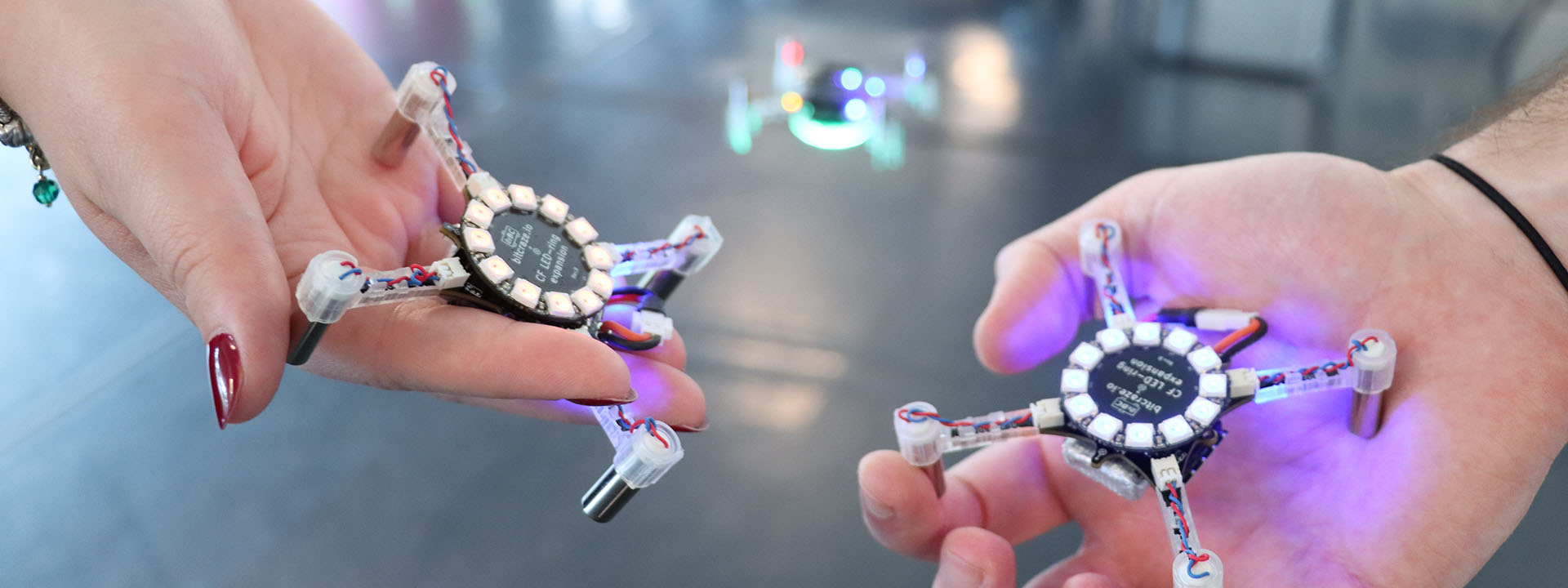
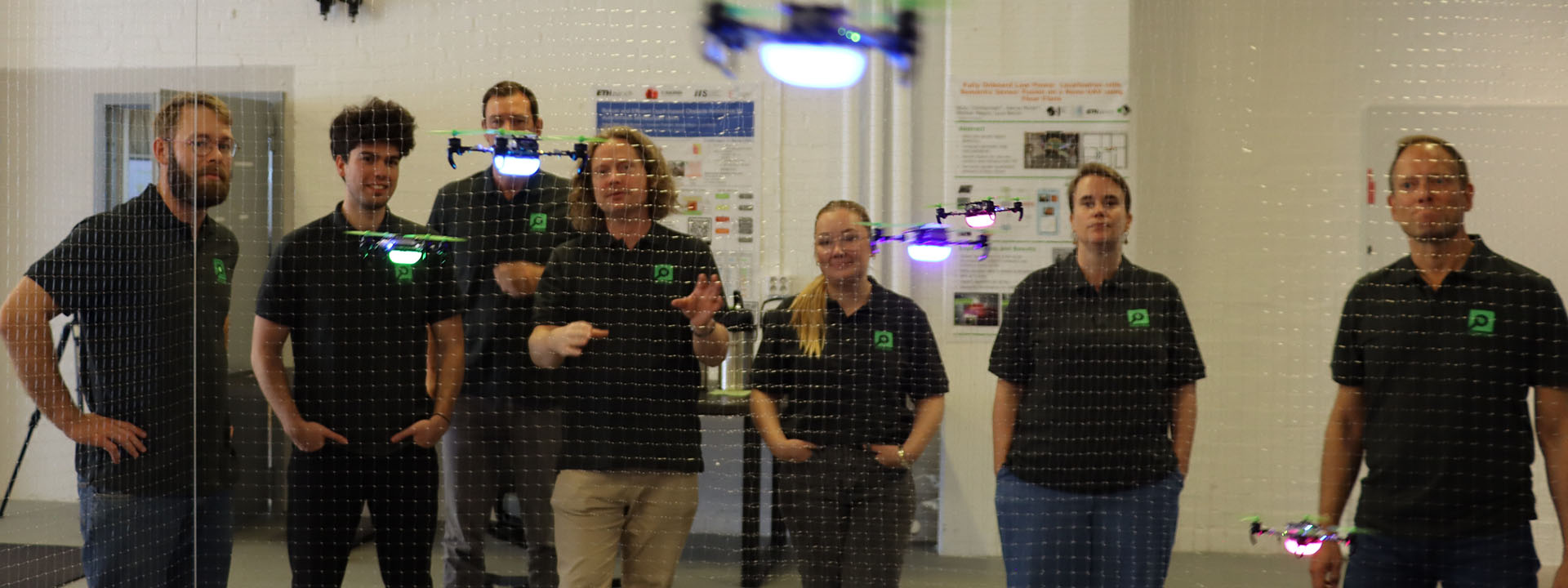
5. Human-Swarm Interaction and Expressive Robotics
An unexpected corner of the research community is the one that adopted the Crazyflie to the human-robot interaction field. It turns out that a swarm of small, quiet, slow-moving drones is a better vehicle for studying how humans interpret and respond to group robot behavior than many ground robot alternatives.
Work in this space ranges from the technical to the almost philosophical. Researchers have studied whether humans perceive swarm motion as intentional and communicative; whether vibrotactile feedback can give operators an intuitive sense of swarm state during physical interaction; how flight formation shapes emotional perception; and how to design impedance-controlled swarms that respond naturally to human touch (see “SwarmTouch: Tactile Interaction of Human with Impedance Controlled Swarm of Nano-Quadrotors” (arXiv).
The Crazyflie’s low injury risk in the event of a collision, its predictable behavior, and its ability to carry sensing and communication payloads make it well-suited to user studies where physical proximity and spontaneous human response are important variables. The fact that the platform is widely available also matters: HRI research benefits from results that can be reproduced in different lab environments with different participant populations.
See “Demonstrating How to Train Your Drone” IEEE paper (10973956) for an example of humans shaping interactions with drones.
A Note on What Makes This Possible
Looking across these five areas, a pattern emerges. In each case, the research is not about the Crazyflie itself. The platform is a means, not an end.
What the Crazyflie provides is a credible physical substrate that researchers can trust to behave consistently, modify freely, and replace cheaply when something goes wrong. The open source firmware means the dynamics are fully inspectable. The transparent hardware means the platform can be extended with custom decks. The stable software ecosystem means results from one year’s experiments can be compared against another year’s, and against results from other labs using the same platform.
If your research uses the Crazyflie in a direction not represented here, we’d like to hear about it. The research portal at bitcraze.io/portals/research lists some of what we know about, but the community is larger and more inventive than any curated list can capture.