This product is in the Early Access stage.

Go big!
Build a quadcopter the size you need, while still running the same code.
How it works
With the BigQuad deck you can transform your Crazyflie® 2.x to a bigger quad by connecting external Electronic speed controllers (ESCs) to the breakout connectors on the deck. The autodetection of the deck makes this transformation possible to do in seconds. The deck also contains breakout header connectors for additional accessories such as external receiver (CPPM input) and GPS. It can also monitor battery voltage and current.
Specifications
Features
- 4 x ESC connectors
- 0.1” header mounting holes for additional connectivity:
- CPPM input (3 pin)
- GPS input (4 pin)
- I2C expansion (4 pin)
- Battery and current monitoring input (3 pin)
- Buzzer output (2 pin)
- Connect one or two additional decks
- Automatic detection of expansion deck
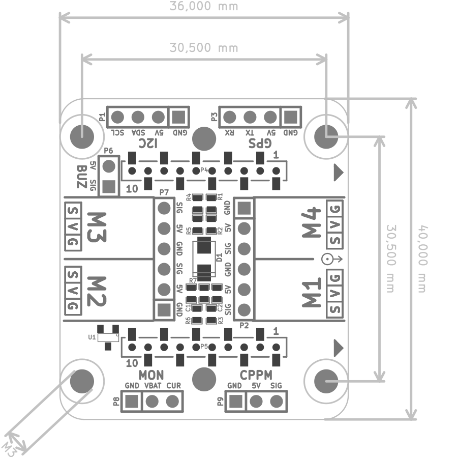
Mechanical specifications
- Weight: 3.8g
- Size (WxHxD): 36x40x5mm
- M3 mounting holes placed 30.5mm square
- Designed for mounting above or under the Crazyflie 2.X
Mechanical drawing
Electrical specification
- Power Crazyflie 2.X with 4.5V - 5.5V from ESC
- BiqQuad deck inputs are 5V tolerant
- Battery voltage monitoring divider scaled for input up to 23V
- Current monitoring input 0V - 3V
- BiqQuad deck and Crazyflie 2.X current consumption:
- ~120mA without any additional decks
- Up to 500mA if Crazyflie 2.X battery is connected and charging
- 1-wire memory for automatic expansion deck detection
Pinout
| Connector | Pin | Signal |
|---|---|---|
| GPS | 1 | GND |
| GPS | 2 | 5V |
| GPS | 3 | TX |
| GPS | 4 | RX |
| I2C | 1 | GND |
| I2C | 2 | 5V |
| I2C | 3 | SDA |
| I2C | 4 | SCL |
| CPPM | 1 | GND |
| CPPM | 2 | 5V |
| CPPM | 3 | signal |
| MON | 1 | GND |
| MON | 2 | VBAT |
| MON | 3 | current |
Usage
Caution
A big quad is dangerous so make sure to be SAFE!
Assembly
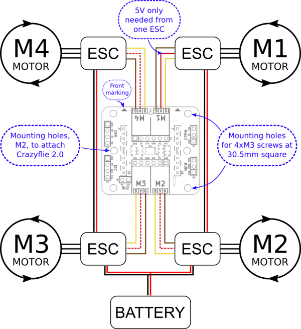
Currently there is only a basic setup but as the development advances so will the documentation. Start by mounting the big quad deck on the frame. After that connect the ESCs according to the diagrams below. Note that the 5V is needed for the motor signals and is not optional.
Basic connection diagram
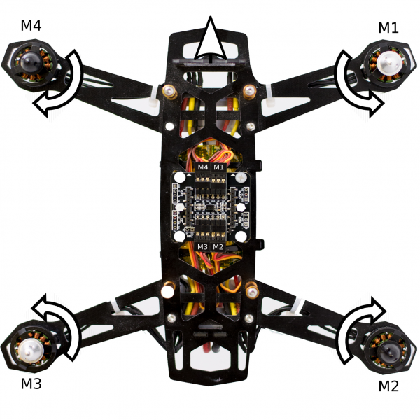
Basic connection picture
Attaching the Crazyflie 2.x
The front of the Crazyflie 2.x should be pointing in the direction of the arrows (front) on the BigQuad deck.
If the frame allows it, the Crazyflie 2.x motors can be kept mounted but it is fine to remove them as well. Attach and connect the Crazyflie 2.x using either the long or short deck pins. Use the included nylon spacer and screws to secure the Crazyflie 2.x in place and to keep it level.
Building Firmware
The BigQuad deck contains a 1-wire memory so it can be automatically detected and functions initialized. However as this currently is an ongoing development and a bigger quads ads a new level of caution we have decided to not enable the functionality by default. Therefore the firmware needs to be compiled with the BigQuad deck enabled in menuconfig.
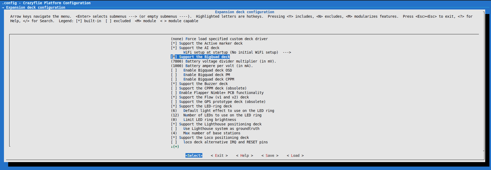
Enable BigQuad features
Make sure to have the crazyflie-firmware code updated to a later version then this commit. Then check the Support the BigQuad deck box in menuconfig under the expansion deck configuration group.
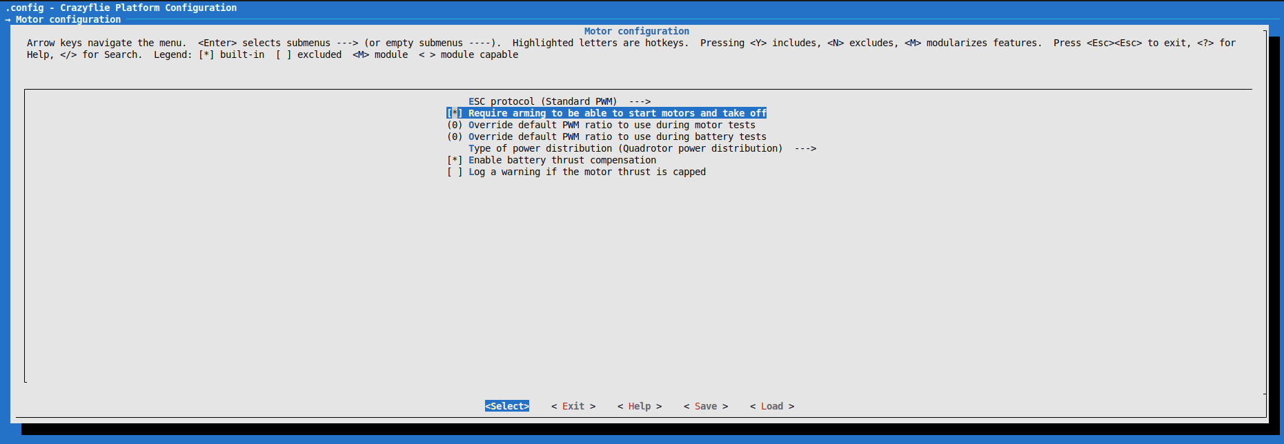
We also suggest enabling the required arming of the motors, which serves as an indication that the drone is ready to fly. This can be done in menuconfig under the motor configuration group.
Build the firmware and flash it using your preferred method. Now when the Crazyflie 2.x is started and it is connected to the BigQuad deck it will start outputting PWM signals to the ESC connectors. The motors will not spin during the Crazyflie 2.x power on self-test (POST).
Early access notes (2021)
- CPPM input is working but calibration and dynamic channel setup is not implemented yet. Doing the first tests with cfclient and gamepad is wise but might not be as reliable as a RC transmitter and receiver, yet.
- When the BQ-Deck is detected it will automatically switch to brushless motor drivers. It will be noted in the cfclient console if it is detected or not.
- 1mbit or 2mbit datarate seem to be more stable when communicating with the BigQuad deck attached. It is wise to do a range test before flying far away.
- Different PID tuning parameters might be needed for it to fly well. Currently this has to be hard coded. Later this will be saved in the EEPROM or in the 1-wire memory.
- External battery voltage/current reading is implemented but no logic behind it, so don’t run out of battery. * You can connect the cable (MON port) and watch the log variable.
- The PWM output is set to 400Hz. Use ESCs which can handle this or compile with new value. There is also the possibility to enable OneShot125 output.
- Be safe, it is experimental software. Run all testing without props!
Development
Errata
Compatibility with Loco deck, microSD and Flow (v2) deck
The Loco deck, microSD and Flow (v2) deck all uses the SPI bus. As the BigQuad deck uses the deck SPI buss pins for possible voltage and current measurement, and they are multiplexed with analog input, the BigQuad deck is not out-of-the-box compatible with these decks.
To work around this issue do the following:
- By removing capacitor C1 on the BigQuad deck (only valid for Rev C, Rev C1 already has this capacitor removed)

- Not having BQ_DECK_ENABLE_PM defined.
- Disabling the extRx functionality by commenting out extRxInit() in bigquad.c
To make it work with the Flow (v2) deck more changes/patching are needed:
- The Flow HW ChipSelect (IO3) interfere with BigQuad PWM and needs to be moved. Cut trace and solder patch on Flow deck from IO3 to IO1.
- Change the CS pin in flowdeck_v1v2.c (IO3 → IO1)
Next problem is how to mount the deck in a nice way on the quad, we leave that up to you.
Resources
- Start here
- Development overview
- FAQ
- Getting help
- Expansion decks of the Crazyflie 2.x
- Datasheet
- Schematics
If you have any further questions please contact support@bitcraze.io