This product is in the Early Access stage.

Make your ideas fly!
Your imagination sets the limits
How it works
The Crazyflie® Bolt 1.1 is a Crazyflie 2.x compatible flight controller for brushless builds. It is intended to have the strengths of the Crazyflie 2.1, but in a slightly bit bigger package. The Crazyflie Bolt 1.1 runs the same firmware base as the Crazyflie 2.1 and includes the same IMU. So you can start out developing using the much smaller Crazyflie 2.1 and then grow as your application grows.
Differences compared to Crazyflie Bolt
- Motor signal output M4 has been moved from PB9 to PB10 to be able to support the DSHOT protocol.
- PCB thickness has been reduced from 1.6mm to 1mm to save weight.
- Revision updated to Rev.H
Specifications
Features
- Firmware compatible with Crazyflie 2.1 and Crazyflie Bolt
- Supports expansion boards with automatic detection
- Integrated radio with dual antenna support (no firmware support yet)
- Wireless firmware updates
- Dual-MCU architecture with dedicated radio/power management SoC for advanced applications
- Real-time logging, graphing and variable setting in addition to full use of expansion boards when using a Crazyradio or Crazyradio PA and a computer
- Integrated power distribution (max 8A / motor)
- Low latency IMU connection
- Low power mode (down to 50uA) in sleep
Onboard microcontrollers
- STM32F405 main application MCU (Cortex-M4, 168MHz, 192kb SRAM, 1Mb flash)
- nRF51822 radio and power management MCU (Cortex-M0, 32Mhz, 16kb SRAM, 128kb flash)
- micro-USB connector
- Full speed USB device interface
- Partial USB OTG capability (USB OTG present but no 5V output)
- 8KB EEPROM
IMU specification
- 3 axis gyro (BMI088 connected via SPI)
- 3 axis accelerometer (BMI088 connected via SPI)
- high precision pressure sensor (BMP388)
Radio specification
- 2.4GHz ISM band radio
- 20 dBm radio amplifier
- Bluetooth Low Energy support with iOS and Android clients available (tested on iOS 7.1+ and Android 4.4+)
- Dual antenna support (2 x uFL connector)
Interface specification
- 1 x Full speed uUSB
- 2 x Crazyflie expansion connectors (see below)
- 2 x u.FL connectors
- 4 x JST-PH ESC connectors
- 1 x XT30 battery connector
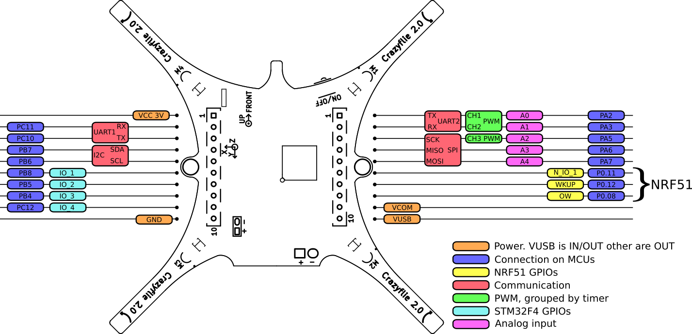
Expansion connector specification
The expansion connector is used to attach decks with additional functionality. Either official Bitcraze decks can be used or custom ones can be design using our KiCad template.
The expansion connector includes the following:
- VCC 3.0V (max 100mA)
- GND
- VCOM (if input above 5V, 5V@400mA, else VBAT@400mA)
- VUSB (both for input and output)
- I2C (400kHz)
- SPI
- 2 x UART
- 4 x GPIO/CS for SPI
- 1-wire bus for expansion identification
- 2 x GPIO connected to nRF51
Please note the following:
- The Crazyflie Bolt 1.1 is a 3.0V system, meaning a high output will be 3.0V but still compatible with a 3.3V system.
- All IO pins are 5V tolerant except PA5 and the NRF51 pins
- The NRF51 pins can be multiplexed with any of the available NRF51 peripheral.
- The STM32F405RG pins can be multiplexed with more functions.
Expansion connector multiplexing (same as CF2.1)
Electrical specifications
- Voltage input 1S-4S (3V to 17V)
- Onboard 5V DC/DC @500mA for voltages above 5V, else passthrough.
- Deep sleep consumption down to 50 uA, 2-4S, with 1S 1mA.
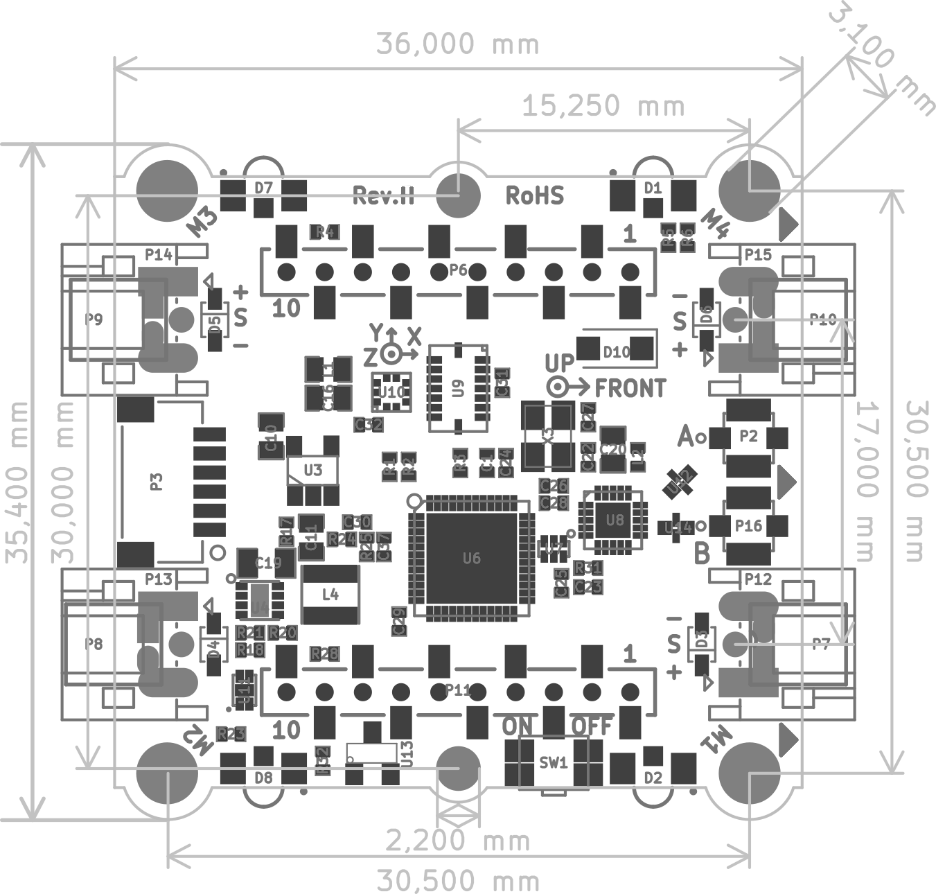
Mechanical specifications
- PCBA size (WxHxD): 35x9x42mm (including connectors but not battery wire)
- Weight: 5.4 g (PCBA only), 7.8 g (PCB + battery cable)
- Battery cable length: 50 mm
- ESC cable length: 60 mm
- Antenna length: 150 mm
- Standard mounting (M3 mounting holes spaced 30.5 mm in square)
Mechanical drawing
Package contents
The Crazyflie Bolt 1.1 is delivered as a kit that contains the following parts:
- 1 x Crazyflie Bolt 1.1 control board
- 1 x Crazyflie Bolt 1.1 (with battery cable attached)
- 1 x External antenna (with u.FL connector)
- 4 x ESC connector cables
- 2 x Short male deck connectors (spare part)
- 2 x Long male deck connectors (spare part)
Usage
Connection diagram
Below is a connection diagram for how the motors should be connected:
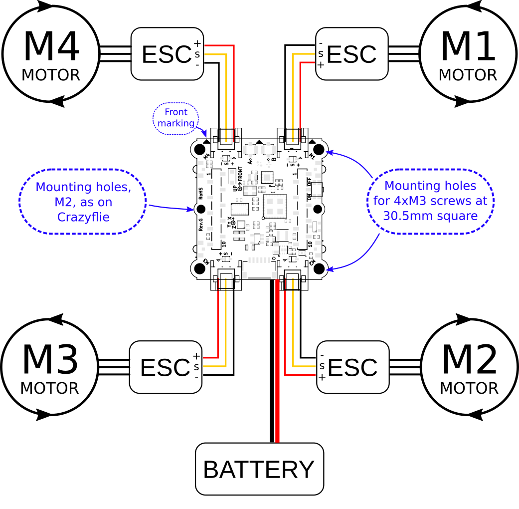
- To not exceed the 8A / ESC connector output the battery voltage, motor and propeller should be selected so this does not happen. The ESC can be rated higher as it does not noticeably effect current draw, only efficiency.
- Preferably select a frame so decks can be attached. It is hard to make e.g. the flow v2 deck and lighthouse deck work at the same time as the battery needs to be placed somewhere, which is normally in the center, above or below the Bolt 1.1 control board.
- 4in1 ESCs can be convenient but for the Bolt 1.1 it is often better to use 4 separate ESC mounted on the arms as this frees up space for decks.
- If higher then 8A is wanted only connect the signal wires from the ESC connectors to the ESC. Preferably still power the Bolt 1.1 control board via the battery connector so the battery voltage can be monitored.
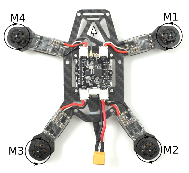
Example connection
Below is an image of an example setup:
Power
The Bolt 1.1 contains a power distribution board (PDB) but it is a bit limiting. The current has to pass a MOSFET, to be able to switch it off, and also the ESC connector. We have tested running 8A though the chain without any limiting heat-up, but that is as far as we would recommend to go. If additional current is wanted, one could bypass the connectors by soldering the ESC directly to the connector soldering pad. The MOSFET is still there but a slight increase should be possible. For higher currents, an external PDB should be used. Other tricks to keep current down, but power up, is to run on higher voltage (3S or 4S) and using low KV motors.
Configuration
The Crazyflie firmware will automatically detect that it is running on a Bolt 1.1 and activate the right modules. However some of the configurations still has to be done during compile time and making them run time configurable is currently work in progress.
Early access notes (2021)
- Different PID tuning parameters might be needed for it to fly well. Currently this has to be hard coded. Later this will be saved in the EEPROM or in the 1-wire memory.
- External battery voltage/current reading is implemented but no logic behind it, so don’t run out of battery.
- The ESC PWM output is set by default to 400Hz. Use ESCs which can handle this or compile with new value. There is also the possibility to enable OneShot125 output.
- It is wise to do a range test before flying far away.
- Be safe, it is experimental software. Run all testing without props!
Development
We think that a development platform should be something more than just making the code available, therefore our software, firmware and utilities have functionality such as logging, real-time parameter setting and wireless firmware updates. The complete development environment for most of the subsystems is available in a virtual machine, so you don’t need to install any tool chains to start developing. Also the virtual machine works just as well for flying.
Once you have made some modifications, simply flash the new firmware over the radio and you are ready to go. For those interested in more advanced development, there is a development adapter kit that supports an easy JTAG/SWD connection to both of the MCUs on the Crazyflie Bolt.
Open Source
The Crazyflie 2.x/Bolt 1.X is an open source project, with source code and hardware schematics both documented and available. Since all of our development tools are open source (except for iOS) we are allowed to redistribute them in an easy way for our users. Aside from the firmware and software projects, there are a number of community supported APIs written in Java, Ruby, C/C++, C# and Javascript.
Change the code
There are ample opportunities to play with the code regardless of which language you prefer. Our client API is written in Python, while there are many other client-side implementations on GitHub written in Ruby, C#, C/C++, JavaScript, Node.JS, Cylon.JS or Java. Or, why not clone our iOS repository and get into some ObjectiveC/Swift.
If you are into embedded systems, the STM32F405 has a lot of processor power you can use for doing experiments, making improvements and adding new features. The expansion decks allow you to experiment, prototype and design your own hardware.
Errata
- When the Bolt 1.1 is running on one cell battery (3-4.2V) the off current is higher than expected and around 1mA. Workaround: Unplug the battery when drones are not used and don’t just use the power off button.
- When the Bolt 1.1 is running on one cell battery (3-4.2V) don’t connect USB at the same time as the battery as the USB is leaking current and charging the battery unintentionally which potentially damages the battery after a while. Workaround: Don’t have the battery and the USB connected at the same time.
Resources
If you have any further questions please contact support@bitcraze.io