This product has reach end-of-life and is not longer being manufactured. Stock might still be available in our online store or though retailers, but it is not recommended to be used for new set-ups.

Motion tracking
Optical flow breakout board for motion detection
How it works
The Flow breakout board is used for motion tracking and can easily be connected to any robotics project or other design.
The motion of a surface, usually the ground, is measured and is reported as delta X and delta Y by the optical flow sensor. The absolute distance (Z) is measured by the Time of Flight ranging sensor. It comes with an Arduino library to easily read the movement data and has a large voltage range for IO and power supply.
The Flow breakout features the VL53L0x ToF sensor and the PMW3901 optical flow sensor.
Specifications
Features
- Fast, accurate distance ranging
- Measures absolute range up to 2m
- Measures movement in X/Y using optical sensor
- Power supply and IO 3V - 5V compatible
- Arduino library for easy usage
- Minimum range for motion tracking is 80mm
Mechanical specifications
- Weight: 2.7g
- Size (WxHxD): 20x26x4mm
- Two M2 mounting holes
Electrical specification
- VL53L0x ToF sensor (I2C)
- PMW3901 optical flow sensor (SPI)
-
VCC: 3V - 5V
- Compatible with 3 to 5V system (power and IO)
- Optical flow requires an SPI port
- ToF ranger requires an I2C port
Interface specification
| Pin | Bus | Signal |
|---|---|---|
| 1 | Power | GND |
| 2 | Power | 3-5V |
| 3 | SPI | CS |
| 4 | SPI | MISO |
| 5 | SPI | CLK |
| 6 | SPI | MOSI |
| 7 | - | Motion IRQ |
| 8 | - | Reset (active low) |
| 9 | I2C | SCL |
| 10 | I2C | SDA |
Usage
Functional description
The signal names are marked on the board:
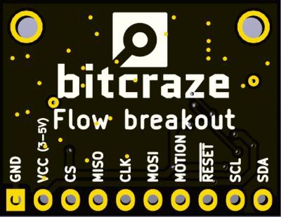
Both sensors are powered by the VCC and GND pins. The board accepts from 3V to 5V, two voltage regulators are generating the required voltage for the sensors and the board has voltage translator for the data signals.
VL53L0 ranging sensor
The VL53L0 ranging sensor is facing front on the board. It is accessible on the I2C pins SCL and SDA.
PMW3901 optical flow sensor
The PMW3901 optical flow sensor is facing front on the board. Is is accessible on the SPI pins CS, MISO, MOSI, CLK. The pins MOTION and /RESET are also connected to the PMW3901. The reset pin can be left floating if not needed.
The optical flow sensor will output motion count. Assuming the board is moving above a flat surface the X/Y orientation is as follow:
![]()
Arduino drivers
You can install Arduino libraries using the Arduino library manager.
The VL53L0x has been succesfully tested with the following drivers:
The PMW3901 arduino driver can be found on github.
Getting started
This getting started will walk you through the process of getting sensor values from the Flow breakout board using an Arduino UNO. The process should be applicable to any arduino-compatible board that has I2C and SPI support.
Hardware requirements
To follow this getting started guide you will need:
- A flow breakout deck with pin header soldered
- An Arduino UNO or compatible
- 8 Female/Male jumper cable
Electrical cabling
The flow breakout board contains two sensors: the PMW3901 optical flow sensor which has an SPI interface and the VL53L0x ToF ranging sensor which has an I2C interface. To use both sensors, both interfaces have to be connected to the Arduino:

Code
Start the Arduino IDE and create a new sketch. Load the following libraries using the library manager:
- VL53L0X
- Bitcraze_PMW3901
Then copy-paste the following code into the sketch and execute it.
#include "Bitcraze_PMW3901.h"
#include <Wire.h>
#include <VL53L0X.h>

VL53L0X rangeSensor;

// Using digital pin 10 for chip select
Bitcraze_PMW3901 flow(10);

void setup() {
  Serial.begin(9600);

  // Initialize flow sensor
  if (!flow.begin()) {
    Serial.println("Initialization of the flow sensor failed");
    while(1) { }
  }

  // Initialize range sensor
  Wire.begin();

  rangeSensor.init();
  rangeSensor.setTimeout(500);
}

int16_t deltaX,deltaY;

void loop() {
  // Get motion count since last call
  flow.readMotionCount(&deltaX, &deltaY);

  // Get single range measurement
  float range = rangeSensor.readRangeSingleMillimeters();

  Serial.print("X: ");
  Serial.print(deltaX);
  Serial.print(", Y: ");
  Serial.print(deltaY);
  Serial.print(", Range: ");
  if (range > 5000) {
    Serial.print("N/A");
  } else {
    Serial.print(range);
  }
  Serial.print("\n");

  delay(100);
}
Output
Open the serial console to see the output from the sensors. If nothing is moving in front of the sensor and the closest object is far away you should see the output below:
X: 0, Y: 0, Range: N/A
X: 0, Y: 0, Range: N/A
X: 0, Y: 0, Range: N/A
X: 0, Y: 0, Range: N/A
X: 0, Y: 0, Range: N/A
X: 0, Y: 0, Range: N/A
X: 0, Y: 0, Range: N/A
If you point the sensor upwards and wave your hand above it you should see something similar to the output below:
X: -1, Y: 0, Range: 123
X: 43, Y: 64, Range: 134
X: 71, Y: 121, Range: 137
X: -1, Y: 39, Range: 123
X: -96, Y: -64, Range: 120
X: -96, Y: -161, Range: 110
X: 32, Y: 0, Range: 123
X: 0, Y: 0, Range: 122
X: 53, Y: 45, Range: 122
X: 21, Y: 133, Range: 118
Resources
If you have any further questions please contact support@bitcraze.io