Lighthouse kalman measurment model

This page describes the generalized measurement model used for the lighthouse in the Kalman state estimator.

In the measurement model we want to get from a sensor position s\vec{s} to rotation angle α\alpha. The first step is to calculate the sensor position in the rotor reference frame.

Use a rotation matrix RrR_r to go from the base station reference frame to the rotor reference frame. For LH2 and the horizontal rotor in LH1 this is the unit matrix, while the vertical drum in LH1 gets Rvert=[100001010]R_{vert} = \left[\begin{array}{ccc} 1 & 0 & 0 \\ 0 & 0 & 1 \\ 0 & -1 & 0 \end{array}\right]

The sensor has position scf\vec{s_{cf}} in the CF reference frame and s=pcf+Rcfscf\vec{s} = \vec{p_{cf}} + R_{cf} \cdot \vec{s_{cf}} in the global reference frame. The sensor position in the base station reference frame is sbs=Rbs1(spbs)=Rbs1(pcfpbs+Rcfscf)s_{bs} = R_{bs}^{-1} \cdot (\vec{s} - \vec{p_{bs}}) = R_{bs}^{-1} \cdot (\vec{p_{cf}} - \vec{p_{bs}} + R_{cf} \cdot \vec{s_{cf}})

Finally, the sensor position in the rotor reference frame is sr=RrRbs1(pcfpbs+Rcfscf)\vec{s_r} = R_r \cdot R_{bs}^{-1} \cdot (\vec{p_{cf}} - \vec{p_{bs}} + R_{cf} \cdot \vec{s_{cf}})

Measurement

The measurement is the rotation angle α\alpha when the sensor is hit by the light plane.

Prediction

To calculate the predicted rotation angle αp\alpha_p we have to go from the sensor position
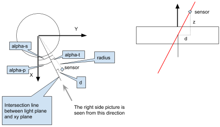
 (sr=(x,y,z)s_r = (x, y, z) in the rotor reference frame) to rotation angle, where the rotation angle is from the X-axis to the line where the light plane intersects the XY-plane. The rotation angle to the sensor αs\alpha_s is the sum of the predicted rotation angle αp\alpha_p and the rotation angle from the intersection line to the sensor αt\alpha_t, caused by the tilt of the light plane, αs=αp+αt\alpha_s = \alpha_p + \alpha_t

Prediction geometry

The rotation angle to the sensor αs\alpha_s is defined by

tanαs=yx\tan \alpha_s = \frac{y}{x} αs=tan1(yx)\alpha_s = \tan^{-1}(\frac{y}{x})

To calculate αt\alpha_t we first have to look at the sensor position projected on the XY-plane (x,y,0)(x, y, 0). The radius to this point is r=x2+y2r = \sqrt{x^2 + y^2}

We also need the distance dd from the intersection line to the sensor, perpendicular to the intersection line, d=rsinαtd=r\sin \alpha_t.

dd can also be calculated using the tilt and z, d=ztantd=z\tan -t. If we combine these

rsinαt=ztantr\sin \alpha_t = z\tan -t sinαt=ztantr=ztantx2+y2\sin \alpha_t = \frac{z\tan -t}{r} = -\frac{z\tan t}{\sqrt{x^2 + y^2}} αt=sin1(ztantx2+y2)=sin1(ztantx2+y2)\alpha_t = \sin^{-1}(-\frac{z\tan t}{\sqrt{x^2 + y^2}}) = -\sin^{-1}(\frac{z\tan t}{\sqrt{x^2 + y^2}})

Finally we can calculate the predicted rotation angle

αp=αsαt=tan1(yx)+sin1(ztantx2+y2)\alpha_p = \alpha_s - \alpha_t = \tan^{-1}(\frac{y}{x}) + \sin^{-1}(\frac{z\tan t}{\sqrt{x^2 + y^2}})

H vector

Calculate the position elements of the H vector in the rotor reference frame

gr=(dαpdxdαpdydαpdz)\vec{g_r} = \begin{pmatrix} \frac{d\alpha_p}{dx} & \frac{d\alpha_p}{dy} & \frac{d\alpha_p}{dz} \end{pmatrix} gr=[yx2+y2xztant(x2+y2)321(ztant)2x2+y2xx2+y2yztant(x2+y2)321(ztant)2x2+y2tantx2+y21(ztant)2x2+y2]\vec{g_r} = \begin{bmatrix} \frac{-y}{x^2 + y^2} - \frac{xz\tan t}{(x^2+y^2)^{\frac{3}{2}} \sqrt{1-\frac{(z\tan t)^2}{x^2+y^2}} } & \frac{x}{x^2 + y^2} - \frac{yz\tan t}{(x^2+y^2)^{\frac{3}{2}} \sqrt{1-\frac{(z\tan t)^2}{x^2+y^2}} } & \frac{\tan t}{\sqrt{x^2+y^2} \sqrt{1-\frac{(z\tan t)^2}{x^2+y^2}} } \end{bmatrix}

Let r=x2+y2r=\sqrt{x^2+y^2} and Q=tantx2+y21(ztant)2x2+y2=tantr1(ztant)2r2=tantr2(ztant)2Q=\frac{\tan t}{\sqrt{x^2+y^2} \sqrt{1-\frac{(z\tan t)^2}{x^2+y^2}}} = \frac{\tan t}{r \sqrt{1-\frac{(z\tan t)^2}{r^2}}} = \frac{\tan t}{\sqrt{r^2-(z\tan t)^2}}

Which leads to

gr=[yxzQx2+y2xyzQx2+y2Q]\vec{g_r} = \begin{bmatrix} \frac{-y-xzQ}{x^2 + y^2} & \frac{x-yzQ}{x^2 + y^2} & Q \end{bmatrix} gr=[yxzQr2xyzQr2Q]\vec{g_r} = \begin{bmatrix} \frac{-y-xzQ}{r^2} & \frac{x-yzQ}{r^2} & Q \end{bmatrix}

Rotate the position elements to the global reference frame to be used in the kalman filter

g=(RrRbs1)1gr=RbsRr1gr\vec{g}=(R_r \cdot R_{bs}^{-1})^{-1} \cdot \vec{g_r} = R_{bs} \cdot R_r^{-1} \cdot \vec{g_r}

Finally we have the H vector

H=(gx,gy,gz,0,0,0...)H=(g_x, g_y, g_z, 0, 0, 0...)

Optimizations

For rotation matrices the following is true

R1=RTR^{-1} = R^T R1(R2v)=(R1R2)vR_1 \cdot (R_2 \cdot \vec{v}) = (R_1 \cdot R_2) \cdot \vec{v}