Top
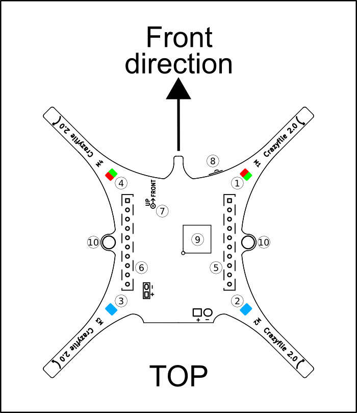
- LED 1: Red/green LED used for heartbeat and low-battery indication
- LED 2: Blue LED fully lit when powered and blinking when bootloading
- LED 3: Blue LED fully lit when powered and blinking when charging
- LED 4: Red/green LED used to indicate radio communication
- Right expansion connector: The expansion port is used to connect expansion boards, either on the top and/or the bottom
- Left expansion connector: The expansion port is used to connect expansion boards, either on the top and/or the bottom
- Expansion board orientation indicator: This indicator should match the expansion boards
- User button: Push button used to power on/off the system. Hold down 3s while powering on to enter bootloader mode. Hold down 10s while powering to enter STM32F4 DFU mode.
- nRF51822: The nRF51822 micro controller
- Mounting holes: Can be used for mechanically mounting something to the platform. The holes are plated, can be grounded by soldering a bridge and are 2mm in diameter (with plating)
Bottom
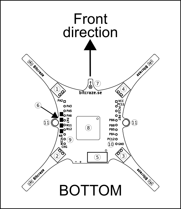
- M1 connector: Motor 1 connector
- M2 connector: Motor 2 connector
- M3 connector: Motor 3 connector
- M4 connector: Motor 4 connector
- STM32F405 debug connector: Connector for debugging the STM32F405 using SWD. For easy access use our debug adapter kit.
- nRF51822 debug pads: Pads for debugging the nRF51822 using SWD. For easy access use our debug adapter kit.
- Expansion board orientation indicator: This indicator should match the expansion boards
- STM32F405 micro controller: The STM32F405 micro controller
- Right expansion connector: The expansion port is used to connect expansion boards, either on the top and/or the bottom
- Left expansion connector: The expansion port is used to connect expansion boards, either on the top and/or the bottom
- Mounting holes: Can be used for mechanically mounting something to the platform. The holes are plated, can be grounded by soldering a bridge and are 2mm in diameter (with plating)