Here is a list of expansion decks that are available for the Crazyflie® 2.x:
| Expansion Deck | Description |
|---|---|
| LED-ring deck | The LED-ring expansion deck |
| Buzzer deck | The Buzzer expansion deck |
| Qi 1.2 wireless charging deck | Qi 1.2 compatible wireless charging deck |
| Prototyping deck | The prototype expansion deck |
| Breakout deck | The breakout expansion deck |
| BigQuad deck | EARLY ACCESS Expansion deck to build a bigger quad |
| Micro SD card deck | Expansion deck to read, write files to SD-card |
| Z-ranger deck V2 | Expansion deck for precise height control. |
| Lighthouse positioning deck | Expansion deck that supports the SteamVR Lighthouse positioning |
| Motion capture marker deck | Expansion deck where motion capture markers can easily be mounted |
| Active marker deck | Expansion deck with active IR LED for motion capture markers |
| Loco Positioning deck | Expansion deck for the Loco positioning system |
| Multi-ranger deck | Expansion deck for detecting obstacles |
| Flow deck V2 | Expansion deck for detecting flow and height |
| AI deck | AI expansion deck |
| Color LED deck | Color LED expansion deck |
Additional information
Expansion board template: The Crazyflie 2.0/2.1 expansion port template
Solder pins to a deck: Instructions to solder pins directly to the deck
Mechanical architecture
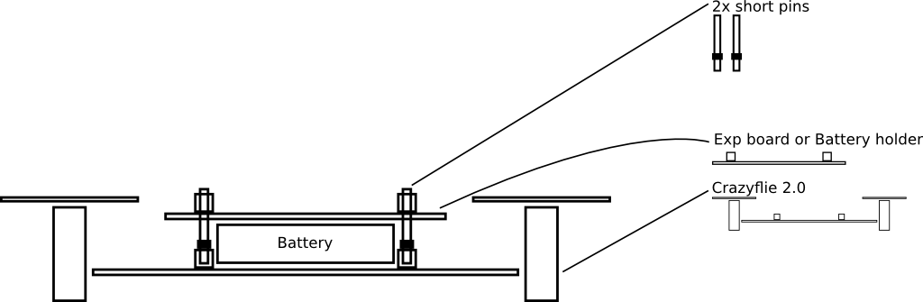
Expansion boards can be installed on top, bottom, or both top and bottom of the Crazyflie 2.x. The Crazyflie 2.x and expansion boards have pass-through connectors that can be fitted with pins. Pins in four different versions exist to permit installation of either one or two expansion boards on the top of the Crazyflie, and one or two expansion boards on the bottom. There should always be one expansion board or battery holder on top to secure the battery, unless the battery is held by other means (ie. rubber band, sticky pad, etc). The pins can be inserted from either the top or the bottom of the Crazyflie 2.x.
Pins
| Pins | Name | Description | Suitable Set Up | Dimensions (Pin length + Plastic spacer + Pin length) | Datasheet |
|---|---|---|---|---|---|
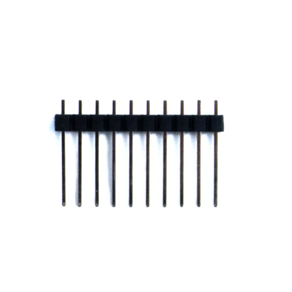 |
Short Pins | Included with the Crazyflie 2.x. Available in store (combined with medium pins) |
Best suited for manual flight with only the Battery Holder Deck mounted on top. | 9mm + 2 mm + 2mm | Datasheet |
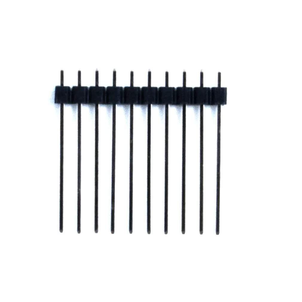 |
Medium Pins | Included with the Crazyflie 2.x. Available in store (combined with short pins) |
Designed for two decks total, one deck on top and one deck on the bottom. | 15mm + 2 mm + 2mm | Datasheet |
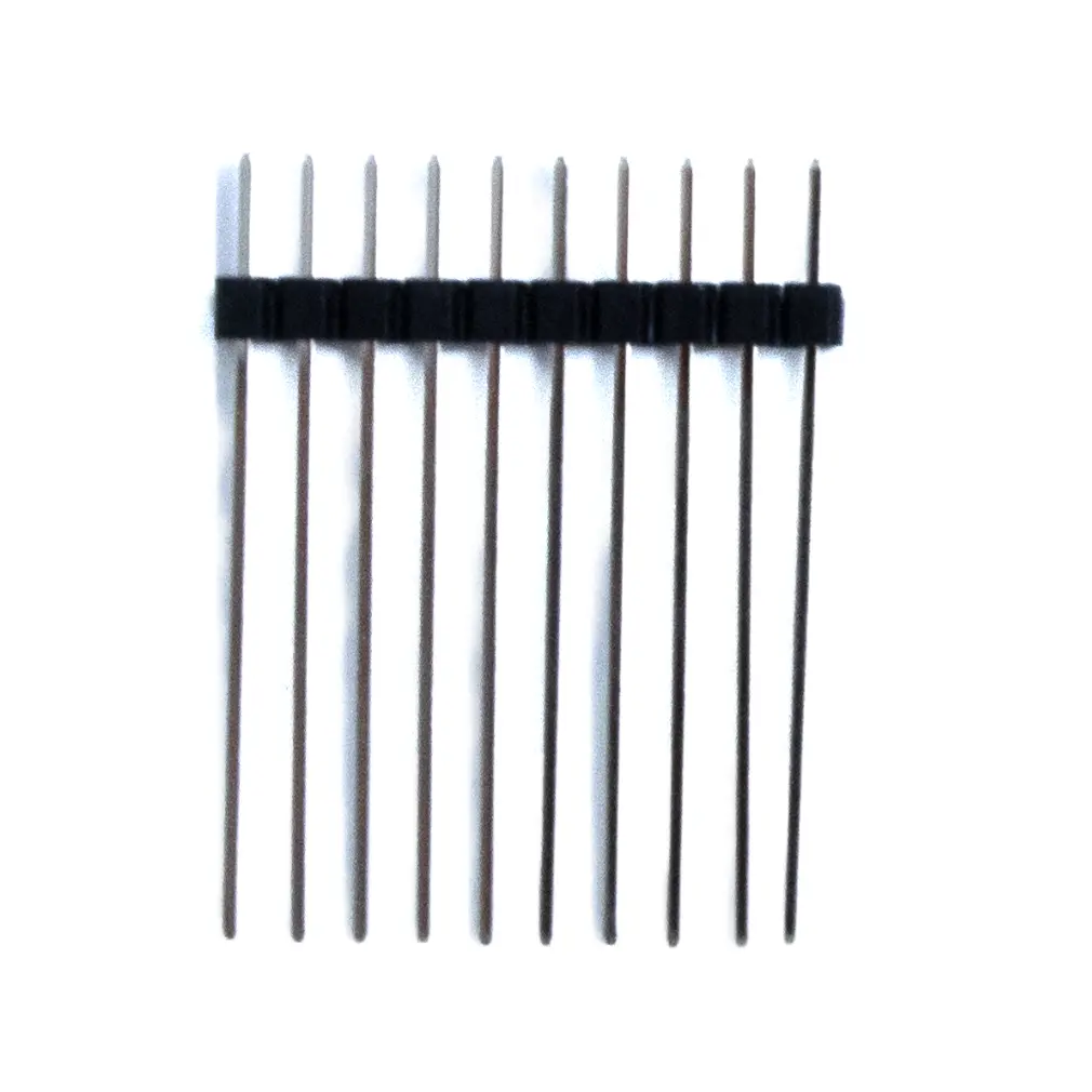 |
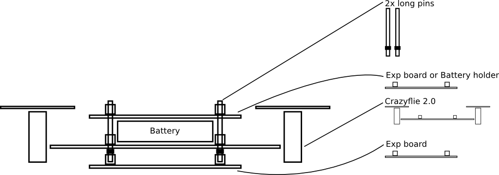
Long Pins (19+2+4mm) | Available in store | Designed for three decks total, optimized for two decks on top and one deck on the bottom. | 19mm + 2mm + 4 mm | Datasheet |
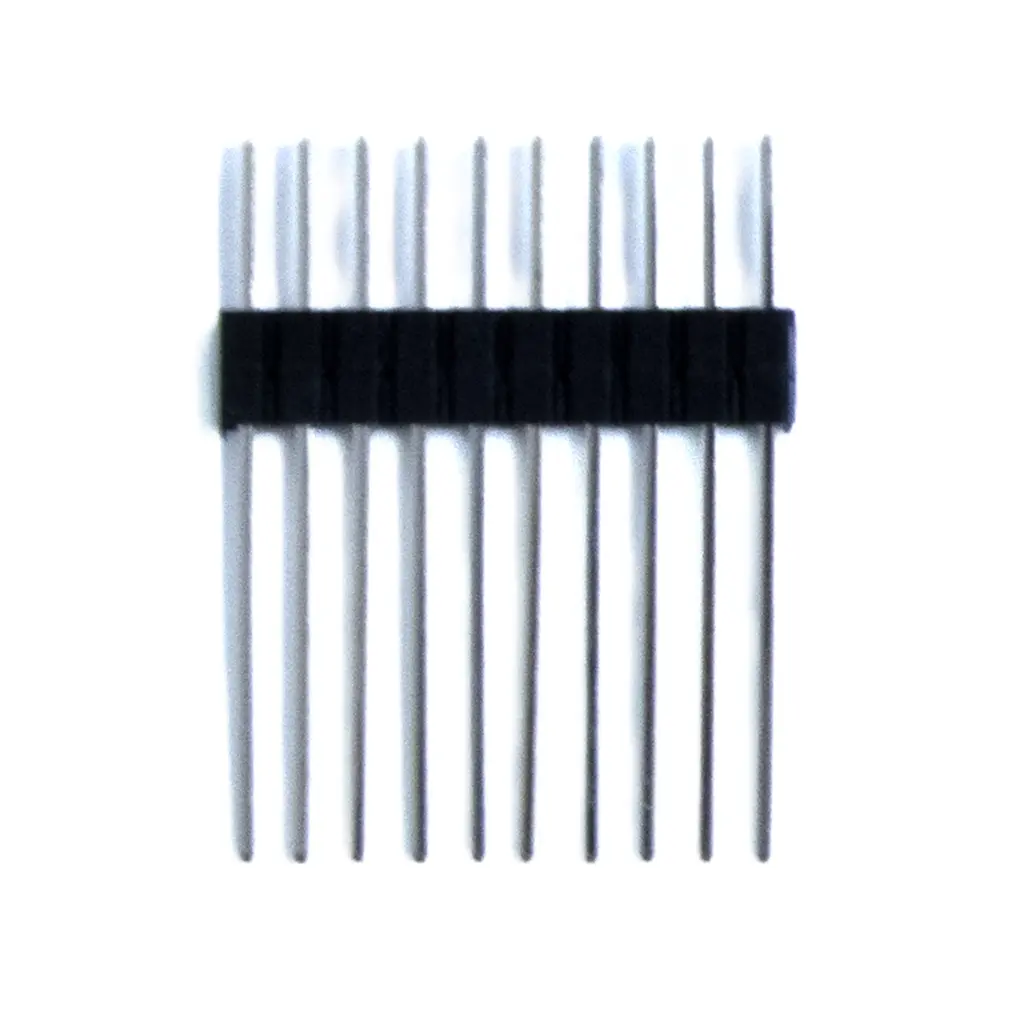 |
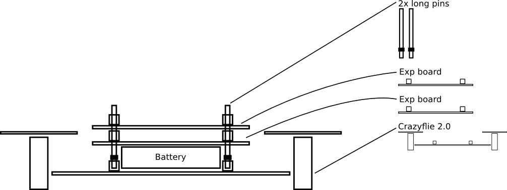
Long Pins (15+4+6mm) | Included with the AI deck. Available in store |
Designed for three decks total, optimized for one deck on top and two decks on the bottom. The wider plastic spacer provides extra support for the AI-deck when mounted underneath, helping keep it level. | 15 mm + 4mm + 6mm | Datasheet |
Orientation
WARNING: It is important to install expansion boards in the right orientation. Installing a board in the wrong orientation might damage the expansion board and the Crazyflie 2.x.
All expansion boards display a logo describing the correct orientation:
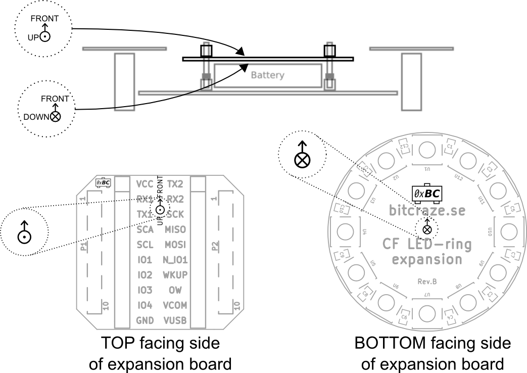
One expansion board on top
One expansion board on top, one on bottom
Two expansion board on top
Expansion port pinout
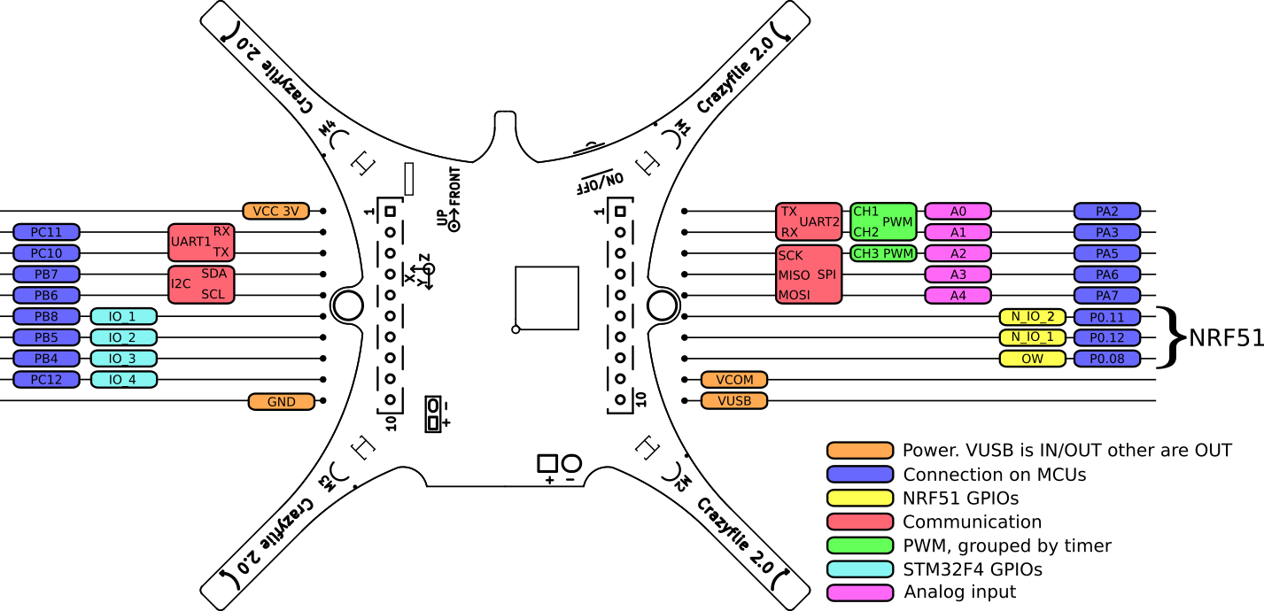
- The Crazyflie 2.x is a 3.0V system, meaning a high output will be 3.0V but still compatible with a 3.3V system.
- VCC can supply max 100mA
- VCOM can supply max 1.0A
- All IO pins are 5V tolerant except PA5 and the NRF51 pins
- The NRF51 pins can be multiplexed with any of the available NRF51 peripheral.
- The STM32F405RG pins can be multiplexed with more functions.
For full specification see the datasheets of the NRF51 and the STM32F405
Expansion board detection
Expansion boards are detected by having a one-wire memory cabled on the OW pin. At startup memories are detected and read by the power management MCU, the nRF51822. If no incompatibility is detected the nRF51 starts the system and makes available the memories content to the application processor, the STM32F4, where the application code is running.
Deck info
| VID | PID | ID | Name | Weight | Consumption | Mount location |
|---|---|---|---|---|---|---|
| 0xBC | 0x01 | bcLedRing | LED-ring deck | 3.3g | 0 - 700mA | Under |
| 0xBC | 0x02 | bcQi | Qi 1.2 wireless charging deck | 5g | N/A | Under |
| 0xBC | 0x04 | bcBuzzer | Buzzer deck | 1.8g | 10mA | Under/Above |
| 0xBC | 0x05 | bcBigQuad | BigQuad deck | 3.8g | N/A | Under/Above |
| 0xBC | 0x06 | bcLoco | Loco Positioning deck | 3.3g | 160mA | Under/Above |
| 0xBC | 0x08 | bcUSD | Micro SD card deck | 1.7g | ~30mA | Under/Above |
| 0xBC | 0x09 | bcZRanger | Z-ranger deck | 1.3g | ~15mA | Under |
| 0xBC | 0x0A | bcFlow | Flow deck | 1.6g | ~40mA | Under |
| 0xBC | 0x0B | bcOA | Obstacle Avoidance | N/A | ~0.3mA | Above |
| 0xBC | 0x0C | bcMultiranger | Multi-ranger deck | 2.3g | ~90mA (depending on mode) | Above |
| 0xBC | 0x0D | bcMocap | Motion capture marker deck | 1.6g | 0mA | Above |
| 0xBC | 0x0E | bcZRanger2 | Z-ranger deck V2 | 1.3g | ~15mA | Under |
| 0xBC | 0x0F | bcFlow2 | Flow deck V2 | 1.6g | ~40mA | Under |
| 0xBC | 0x10 | bcLighthouse4 | Lighthouse positioning deck | 2.7g | ~40mA | Above |
| 0xBC | 0x11 | bcActiveM | Active marker deck | 3.3g | ~40mA | Above |
| 0xBC | 0x12 | bcAI | AI deck | 4.4g | depending on deck app | Under/Above |
| 0xBC | 0x13 | bcColorLedBot | Color LED deck (bottom-mounted) | 3.5g | up to 300mA per channel | Under |
| 0xBC | 0x14 | bcColorLedTop | Color LED deck (top-mounted) | 3.5g | up to 300mA per channel | Above |
Deck pin allocation
Below is a table showing which pins each deck uses. The table also contains information about boards that are not released yet, these are subject to change.
Assignments in parenthesis are unconnected but connectable via solder bridges or 0 Ohm resistors and are thus alternative connections. The idea is to make it possible to re-route a connection if you want to use two decks where the connections collide.
| UART1 | UART1 | I2C | I2C | STM32 IO | STM32 IO | STM32 IO | STM32 IO | UART2 | UART2 | SPI | SPI | SPI | nRF51 IO | nRF51 IO | ||
|---|---|---|---|---|---|---|---|---|---|---|---|---|---|---|---|---|
| Name | RX1 | TX1 | SDA | SCL | IO1 | IO2 | IO3 | IO4 | TX2 | RX2 | SCK | MOSI | MISO | NIO1 | NIO2 | PWR |
| LED-ring deck | PWM | PWM | VCOM | |||||||||||||
| Qi 1.2 wireless charging deck | CHG | N/A | ||||||||||||||
| Micro SD card deck | (MISO) | (SCK) | (CS) | (CS) | (CS) | CS/(MOSI) | SCK | MOSI | MISO | VCC | ||||||
| Loco Positioning deck | IRQ | RST | CS | (IRQ) | (RST) | SCK | MOSI | MISO | VCOM | |||||||
| BigQuad deck | (RX1) | (TX1) | (SDA) | (SCL) | PWM | PWM | (IO) | PWM | PWM | (ADC) | (ADC) | (IO) | N/A | |||
| Buzzer deck | PWM | PWM | N/A | |||||||||||||
| Z-ranger deck V2 , Z-ranger deck V1 | SDA | SCL | (VL53_IO) | VCC | ||||||||||||
| Flow deck V2 , Flow deck V1 | SDA | SCL | (RST/MOT/IO) | CS | (RST) | (MOT) | SCK | MOSI | MISO | VCC | ||||||
| Multi-ranger deck | SDA | SCL | VCOM | |||||||||||||
| Motion capture marker deck | (BTN/IO) | (BTN/IO) | N/A | |||||||||||||
| Lighthouse positioning deck | RX1 | TX1 | (SDA) | (SCL) | N/A | |||||||||||
| Active marker deck | SDA | SCL | N/A | |||||||||||||
| AI deck | RX1 | TX1 | SDA | SCL | BOOT | RST | TX2 | RX2 | VCOM | |||||||
| Color LED deck | SDA | SCL | VCOM |
Compatibility matrixes
Platform - deck
This table shows which deck that works on which platform.
| Expansion Deck | Crazyflie 2.0, 2.1(+) | Crazyflie 2.1 Brushless | Crazyflie Bolt 1.1 |
|---|---|---|---|
| LED-ring deck | yes | no | yes* |
| Qi 1.2 wireless charging deck | yes | yes | yes |
| Micro SD card deck | yes | yes | yes |
| Loco Positioning deck | yes | yes | yes |
| BigQuad deck | yes | yes | yes |
| Buzzer deck | yes | yes | yes |
| Z-ranger deck V2 , Z-ranger deck V1 | yes | yes | yes |
| Flow deck V2 , Flow deck V1 | yes | yes | yes |
| Multi-ranger deck | yes | yes | yes |
| Motion capture marker deck | yes | yes | yes |
| Lighthouse positioning deck | yes | yes | yes |
| Active marker deck | yes | yes | yes |
| AI deck | yes | yes | yes |
| Color LED deck | yes | yes | yes* |
* The LED decks will work on the Bolt but not at full power due to a power budget of 500 mA total.
Deck - deck
This table shows which decks that can be used at the same time.
Note: This matrix is for unmodified decks and the standard firmware. Some decks can be modified to use other pins on the expansion port and thus work with decks that are marked as not compatible. Also decks that are normally physically blocking each other are marked as not compatible.
| LED-ring deck | Qi 1.2 wireless charging deck | Micro SD card deck | Loco Positioning deck | BigQuad deck | Buzzer deck | Z-ranger deck V2 , Z-ranger V1 | Flow deck V2 , Flow deck V1 | Multi-ranger deck | Motion capture marker deck | Lighthouse positioning deck | Active marker deck | AI deck | Color LED deck | |
|---|---|---|---|---|---|---|---|---|---|---|---|---|---|---|
| LED-ring deck | - | yes | yes | yes | yes | yes | yes | yes | yes | yes | ||||
| Qi 1.2 wireless charging deck | - | yes | yes | yes | yes | yes | yes | yes | yes | yes | yes1 | |||
| Micro SD card deck | yes | yes | - | yes2 | yes | yes | yes | yes2 | yes | yes | yes | yes | 5 | yes |
| Loco Positioning deck | yes | yes | yes2 | - | yes | yes | yes | yes | yes | yes | 3 | yes | 6 | yes |
| BigQuad deck | yes | yes | yes | - | yes | yes | yes | 3 | yes | 7 | yes | |||
| Buzzer deck | yes | yes | yes | yes | - | yes | yes | yes | yes | yes | yes | 7 | yes | |
| Z-ranger deck V2 , Z-ranger V1 | yes | yes | yes | yes | - | yes | yes | yes | yes | yes | yes | |||
| Flow deck V2 , Flow deck V1 | yes2 | yes | yes | - | yes | yes | yes | yes | yes | yes | ||||
| Multi-ranger deck | yes | yes | yes | yes | yes | yes | yes | yes | - | yes | yes | yes | yes | yes |
| Motion capture marker deck | yes | yes | yes | yes | yes | yes | yes | yes | yes | - | yes | yes | yes | |
| Lighthouse positioning deck | yes | yes | yes | 3 | 3 | yes | yes | yes | yes | yes | - | 4 | yes | |
| Active marker deck | yes | yes | yes | yes | yes | yes | yes | yes | yes | - | yes | yes | ||
| AI deck | yes | yes | 5 | 6 | 7 | 7 | yes | yes | yes | yes | 4 | yes | - | yes |
| Color LED deck | yes | yes1 | yes | yes | yes | yes | yes | yes | yes | yes | yes | yes | yes | - |
Notes:
- The Qi deck is only compatible with the top-mounted Color LED deck. Mounting the Color LED deck on the bottom will physically block the Qi deck.
- SPI sharing might limit the logging speed of the uSD-card deck.
- Could be patched using soldering bridges or can be supported in the future, SW update
- The GAP8 module is connected to UART1, so if that is enabled there will be conflicts
- The Micro-SD deck and AI deck both use IO4, the Micro-SD deck needs to be patched to use another IO for Chip Select
- With a patch or workaround it is possible
- CPX uses UART2 to communicate with the ESP32 by default, if that is enabled there will be conflicts.