Introduction
The Lighthouse positioning system uses the SteamVR Base Stations from Valve Inc. together with the Lighthouse positioning deck mounted on the Crazyflie®. This system enables the Crazyflie to estimate its position and orientation within a global coordinate system.
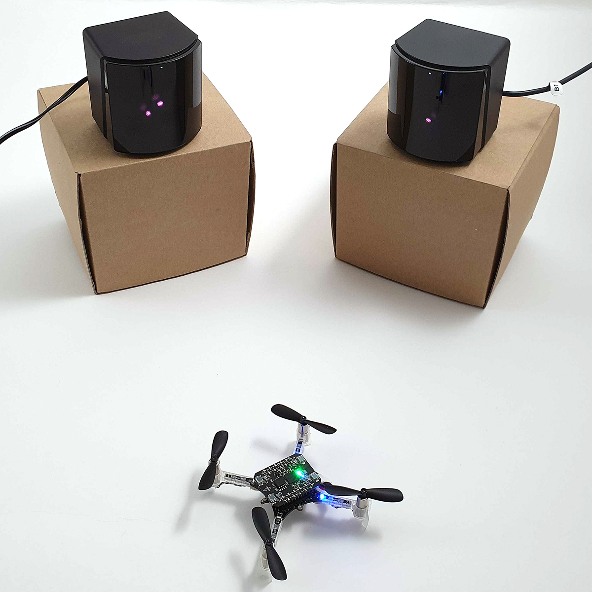
Video Tutorial
This tutorial is also available as a video. The text tutorial on this page goes into more detail, so it’s worth following along if you run into trouble or want the full picture.
Prerequisites - hardware
Make sure that you have the following available:
- A Crazyflie platform - if you haven’t set it up yet, follow the Getting started tutorial.
- A Lighthouse positioning deck .
- 2-4 Lighthouse base stations V2.0 (recommended) or 2 Lighthouse base stations V1.0.
- Crazyradio 2.0 or Crazyradio PA - if you haven’t set the Crazyradio 2.0 up yet, follow the Getting started with the Crazyradio 2.0 tutorial.
Prerequisites - software
- The latest version of the Crazyflie client. Follow the Installation instructions.
Preparing the Crazyflie
The first thing to do is to make sure the firmware in the Crazyflie and Lighthouse deck is up to date.
Mount the Lighthouse deck
For mounting the Lighthouse positioning deck on a Crazyflie follow the Getting started with expansion decks tutorial. Be careful when mounting the Lighthouse positioning deck using the long pins. Make sure they do not block the laser sweeps from reaching the sensors on the lighthouse deck, as this could affect the drone’s performance.
Update firmware in the Crazyflie and Lighthouse deck
Note: The Lighthouse deck firmware is updated automatically together with the Crazyflie firmware when flashing from the client. The deck needs to be mounted on the Crazyflie during the flashing process.
Follow the firmware upgrade instructions.
Preparing the base stations
Before setting up the system you need to configure the channel of the base stations.
Make sure you have permission to write to serial ports
In Linux, non-root users typically don’t have permission to access serial devices by default. If you are on a Linux system, make sure that your user account has the required access rights. This can be done by adding your user to the dialout group and restarting. Adding a user to a group in Linux is done using the usermod command, which requires root permissions:
$ sudo usermod -aG dialout [username]
Replace [username] above with your own username. After running the command, restart your computer and you will then have permission to access serial devices.
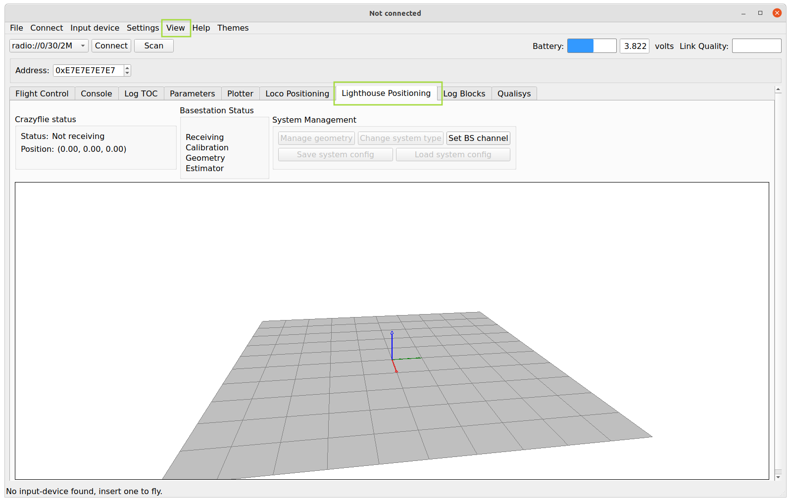
Open the Crazyflie Client and click the Lighthouse Tab
You can open the Lighthouse tab by selecting View->Tabs->Lighthouse Positioning.
Configure the base stations channel
V2 base stations are configured from the Crazyflie client and their channel must be set to a unique id between 1 and the number of supported base stations.
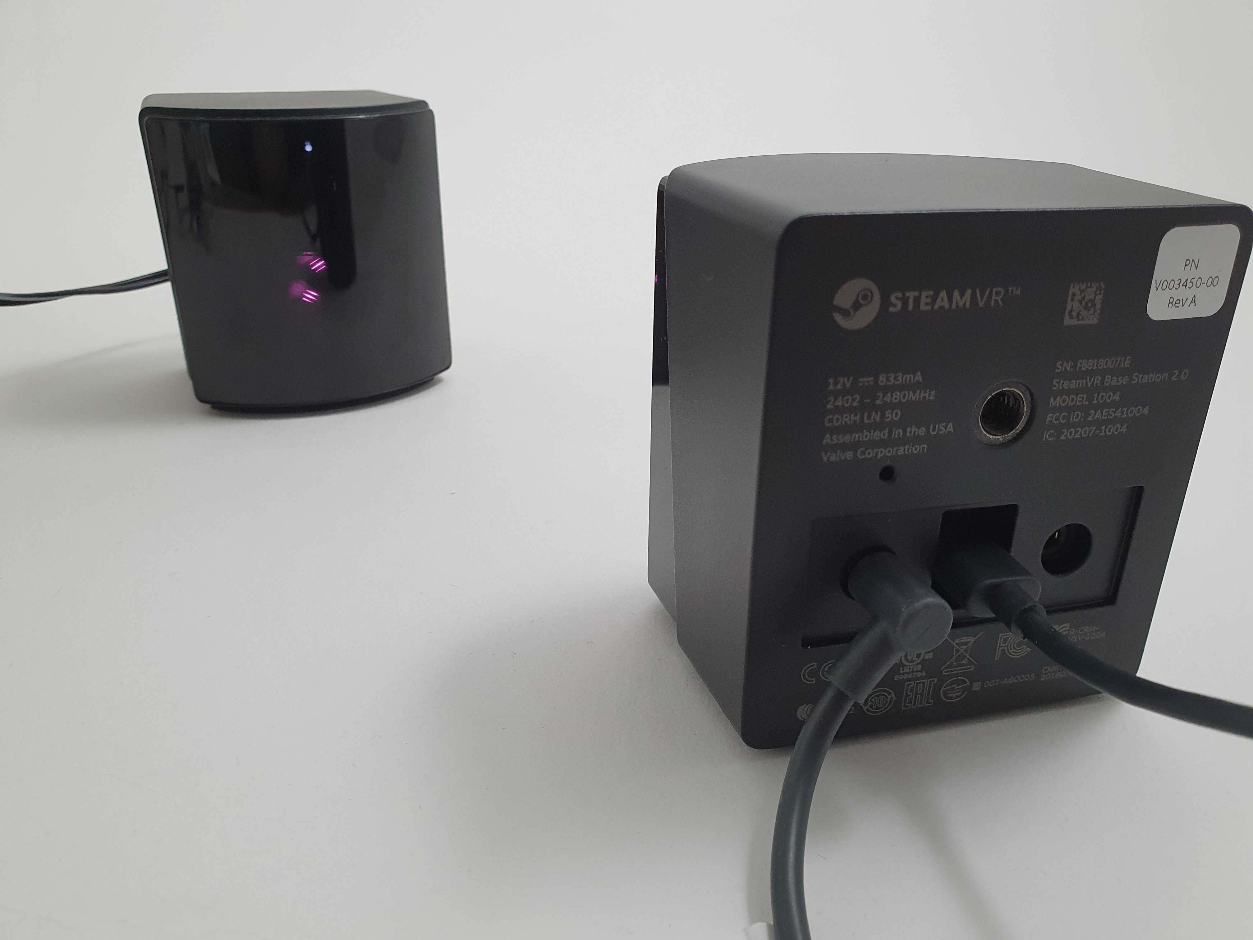
For one base station at a time:
-
Power on the base station with its powerblock and connect it with a micro-usb cable to the computer.
-
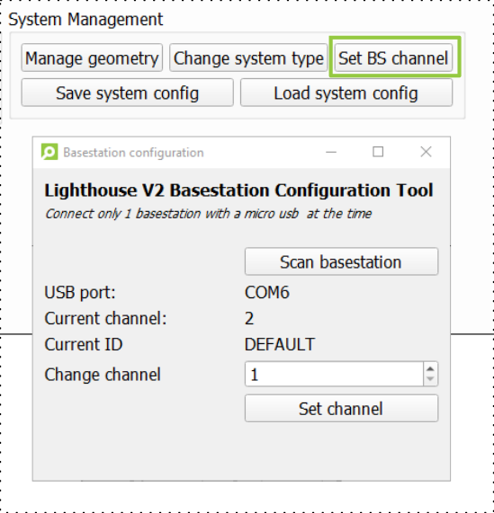
Open up the base station configuration tool in the Lighthouse tab of the Crazyflie client by clicking the Set BS Channel button.
-
Scan for the base station and check the Current channel. If the base station is never used, this value is probably 0.
-
Put the wanted channel (1 to 4) in Change Channel and click the Set Channel button. Each base station should have a unique channel.
-
Wait until you see the ‘success!’ message before disconnecting and repeat the steps for the next base station.
On V1 base stations you change the mode with the small button on the back of the base station. The modes should be changed to ‘a’ and ‘b’ if you are using a sync cable and ‘b’ and ‘c’ without a sync cable.
Set up the base stations in the flight area
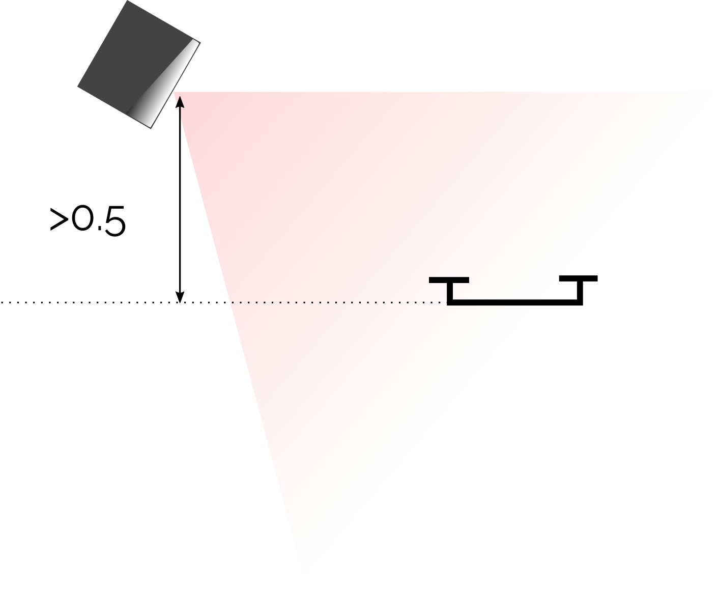
After the base station’s channels are correctly set, you can mount them in your flight area using a wall mount or a tripod. Each base station requires only a power supply; the USB connection is not needed. The maximum flight area for two base stations is about 4 x 4 x 2 m, but as long as the Crazyflie is not further away than 6 meters from at least one base station, it will receive positioning data. Note that the lighthouse sensors are placed on the top of the Lighthouse positioning deck and that the base stations must be above the Crazyflie to be received.
Make sure the following conditions are met in your flight area:
- The base stations should be about at least 50 cm above the expected flight area of the Crazyflie.
- Remove the mirrors or large reflective items in the area.
- Avoid direct sunlight as it can interfere with the lighthouse sensors.
- Make sure the base stations have a clear line of sight to the Crazyflie throughout the flight area.
Setting up the System
This section explains how to collect the calibration and geometry data and configure your Crazyflie for flight using the Lighthouse positioning system.
Connect to the Crazyflie with the Client
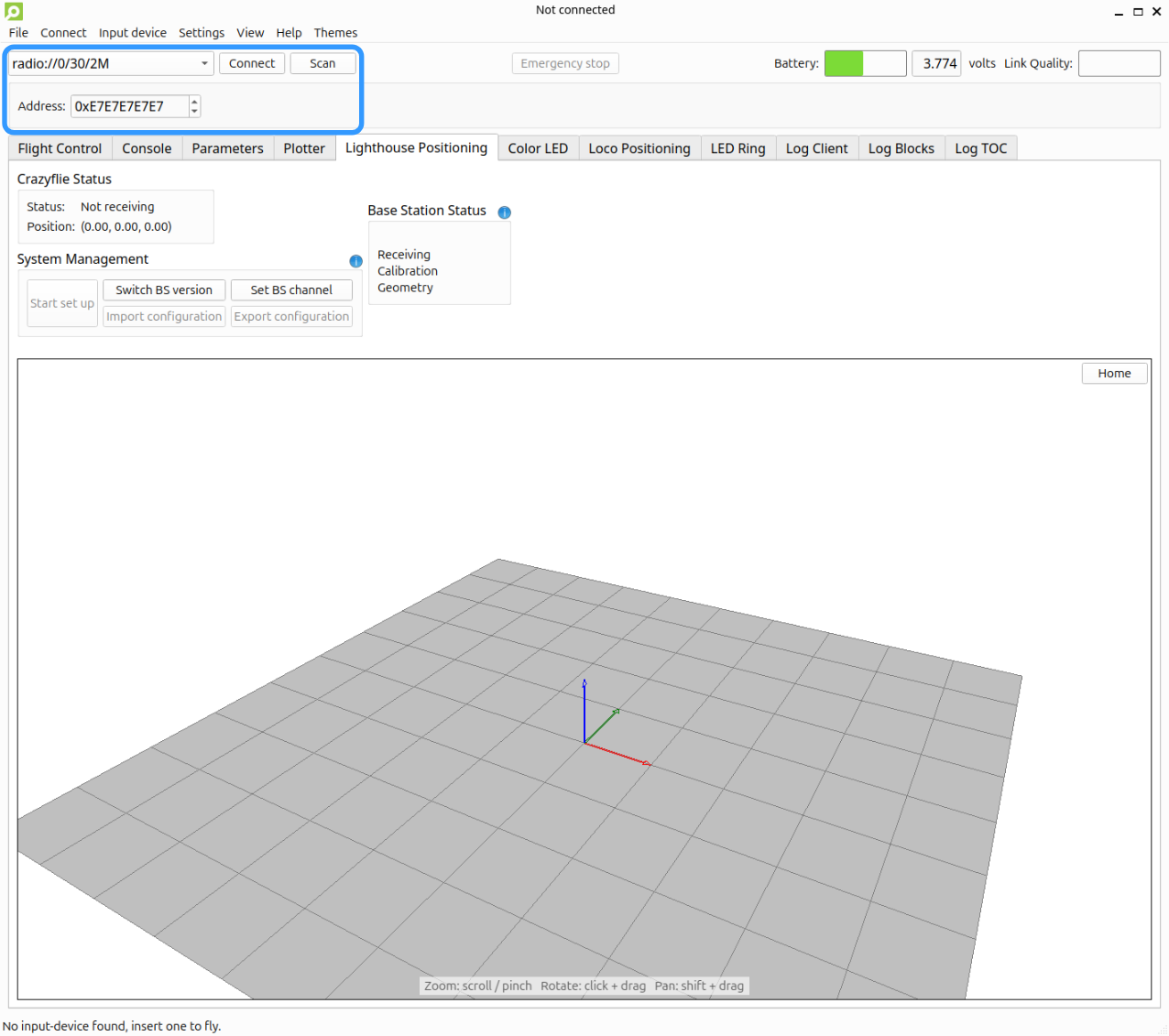
Open the CF client and connect to the Crazyflie.
Select system type
The Crazyflie needs to know what type of base stations are used to be able to decode the light sweeps correctly.
Click the Switch BS version button and select the appropriate version. This is stored in the Crazyflie and is automatically used the next time it starts.
Wait for calibration of the base stations
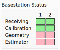
Place the Crazyflie within the flight area so that it has a clear line of sight to all base stations. Wait approximately 20 seconds for the calibration data to be received before proceeding.
Estimate the geometry
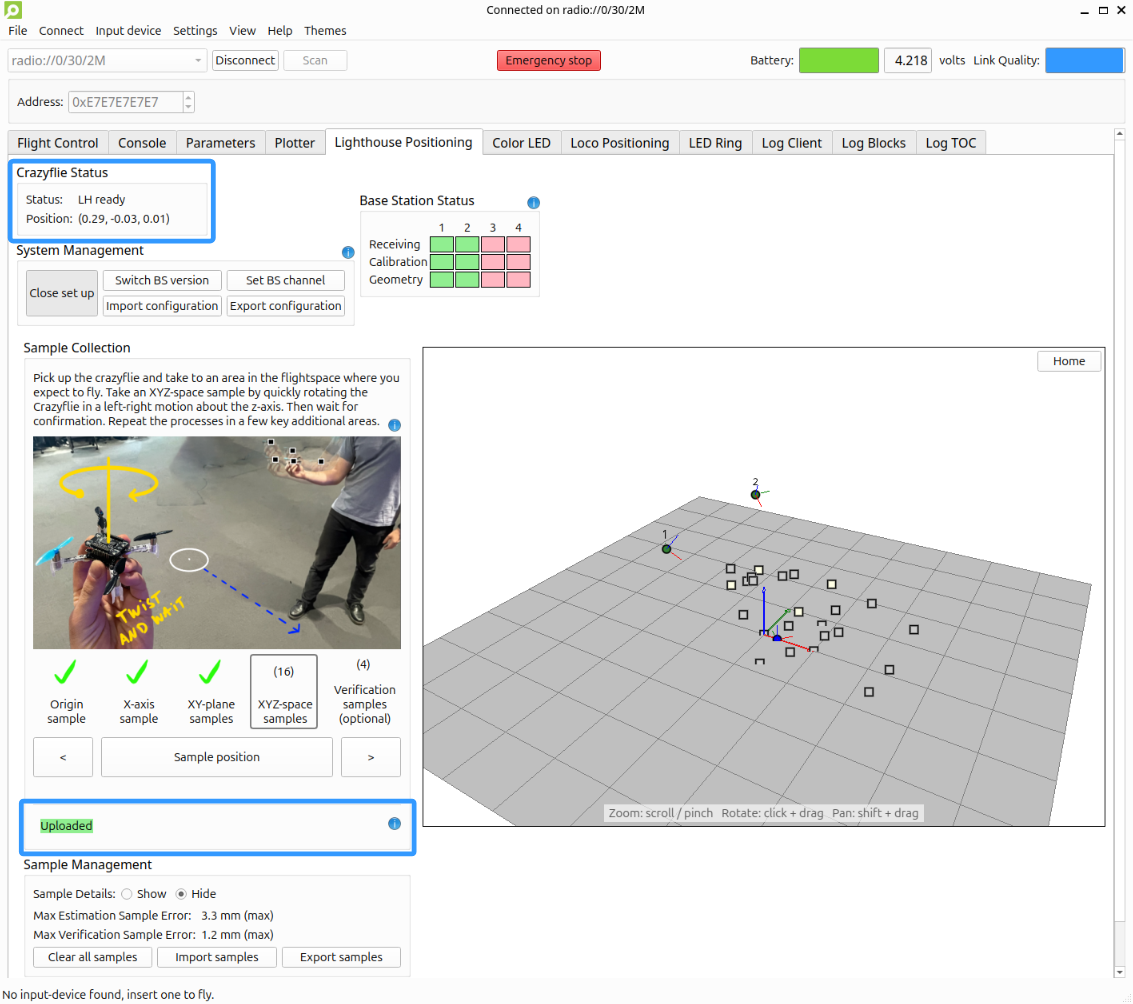
Once you have received the calibration data, it is time to estimate where the base stations are located. For this geometry estimation process, a series of estimation samples need to be collected. The final result, is a configuration file that is stored in the Crazyflie and used to estimate its position.
-
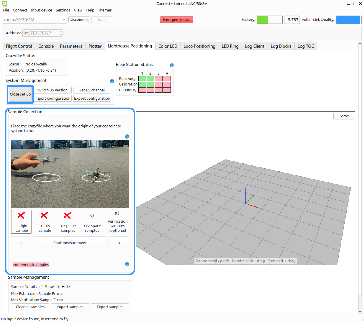
Press Start set up in the System Management section to expand the setup sections.
-
Follow the steps in the Sample Collection section for collecting the estimation and optionally some verification samples. Use the “<” and “>” buttons to move between the steps:
- Origin sample: Place the Crazyflie at the desired origin of your coordinate system and press Start measurement
- X-axis sample: Place the Crazyflie 1 m along the positive X-axis and press Start measurement
- XY-plane samples: Place the Crazyflie in the XY-plane on the floor (not on the X-axis) and press Start measurement. You can repeat this multiple times to get a more precise approximation.
- XYZ-space samples: Carry the Crazyflie to a position in your flight space. To record a sample, quickly rotate it left-right around its Z-axis and hold it still until confirmation. Alternatively, click the Sample Position button while holding the Crazyflie still.
- Verification samples (optional): Unlike the estimation samples, verification samples are not used for the system’s geometry estimation. They can be used for checking the accuracy of areas between the estimation samples. If the verification sample error is high, try adding more XYZ-space samples around the verification location. For more information, see the Sample details section below.
The geometry is estimated and uploaded to the Crazyflie automatically. The status label turns green and shows Uploaded when done.
Check the positioning
The Lighthouse Deck’s LED should now be green, and the 3D visualization should show the base stations with their channels and the Crazyflie as a blue dot.
Sanity-check the position estimation by placing the Crazyflie in different positions. The estimated position should remain relatively stable and should not drift or jump unexpectedly.
Sample details
This section is for users who want to inspect and potentially improve their geometry configuration without redoing the entire estimation process.
The Base stations and Samples tables are shown when Show is selected under Sample Details in the Sample Management section.
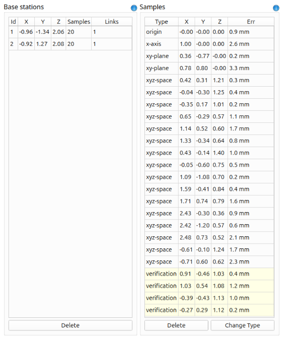
The Base stations table shows the estimated position of each base station and how many samples link it to other base stations. The minimum requirement is that each base station links to at least one other; the more cross-links there are, the more robust the solution.
The Samples table lists all collected samples (both estimation and verification) along with their error. The error measures how closely the base stations agree on the Crazyflie’s position at that sampling location: a low error means the geometry fits that sample well, a high error (> 10 mm) means the base stations disagree.
- For estimation samples with a high error, the most effective fix is to delete the sample.
- For verification samples with a high error, add more XYZ-space samples in that area and let the geometry re-estimate. Verification errors give the most useful insight about real-world accuracy, since they reflect positions that were not used during estimation.
For a full description of each button, see the cfclient lighthouse tab user guide.
Test flight
Now that the system is set up, let’s do a short test flight!
Switch to the Flight control tab
Click the Flight control tab in the Crazyflie client.
Find the controls
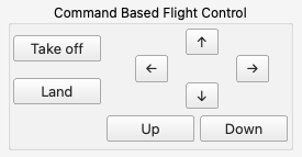
In the bottom right corner you will find buttons for simple command based flight.
Take off and fly
Click the Take off button to start flying and use the other controls to move around.
Next
- With the base stations V2.0, it is possible to use more than 4 base stations but firmware modifications are required. See the instructions to configure the firmware to enable support for more than 4 Lighthouse base stations.
- See the cfclient lighthouse tab user guide for a detailed explanation of each button.
- The Lighthouse system documentation presents the in-depth theory of the lighthouse positioning system and more advanced guides.