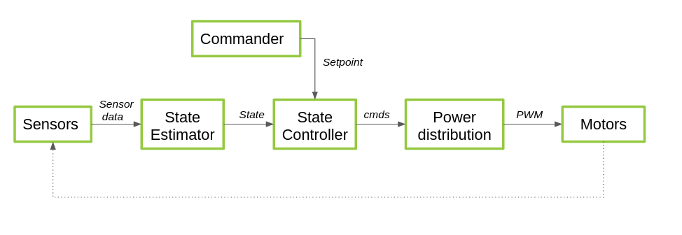
This page is meant as an introduction and overview of the path from sensor acquisition to motor control, also called the stabilizer module. It will not go into detail but it mostly gives a general outline of how the sensor measurements go to the state estimators to the controllers and finally distributed to the motors by power distribution. Of course, the motors have an affect on how the Crazyflie flies and that indirectly has an effect on what the sensors detect in the next time step.
- Sensors
- State Estimation
- State Controller
- Commander Framework
- Power Distribution
- Configure estimators and control
Overview
Modules
Sensors
Sensors are essential for the flight of a Crazyflie. Here is selection of the sensors listed that the Crazyflie eventually uses for state estimation:
- On-board Sensors
- Accelerometer: acceleration in body fixed coordinates in m/s2
- Gyroscope: angle rate in roll pitch and yaw (rad/s)
- Pressure Sensor: Air pressure in mBar
- Flowdeck v2
- ToF sensor*: Distance to a surface in mili-meters
- Optical flow sensor: The detection movement of pixels in px per timesample
- Loco positioning deck:
- Ultra Wide band module: The distance between two UWB modules or TDOA*** in meters.
- Lighthouse deck:
- IR receivers: Sweep angle of htc vive base stations in radians.
- MoCap: Active Marker deck or Motion capture deck
- External calculated position and orientation, usually broadcasted to the Crazyflie by Crazyradio.
*Time-of-Flight
**Zranger v2 also contains a laser-ranger
***Time-difference of Arrival
State Estimation
There are 2 state estimators in the Crazyflie:
- Complementary Filter
- Extended Kalman Filter
Go to the state estimation page for more in-depth information.
State Controller
There are 3 controllers in the Crazyflie
- PID controller
- INDI controller
- Mellinger controller
Go to the controllers page, for more in-depth information.
Commander Framework
A desired state can be handled by the set-point structure in position or attitude, which can be set by the cflib or the High Level commander.
Go to the Commander page, for more in-depth information.
Power Distribution
After the state controller has sent out its commands, this is not the end of the line yet. The controllers send out their commands relating to their yaw, roll and pitch angles. How the motors should respond in order to adhere these attitude based commands depends on a few factors:
- Motors:
- Brushed: The Crazyflie 2.X platforms with brushed motors support battery compensation, which adjusts the motor outputs to maintain consistent thrust across the entire battery range. For implementation details, check out
motors.c, as well as the PWM to Thrust investigations and the Battery Compensation documentation of those same motors. - Brushless: The Crazyflie 2.1 Brushless and the Crazyflie Bolt support brushless motor control. Battery compensation is also available for the Crazyflie 2.1 Brushless, but it not on the Crazyflie Bolt, since the settings depend on the user’s motor configuration. For more information, check out the product page of the Bolt.
- Brushed: The Crazyflie 2.X platforms with brushed motors support battery compensation, which adjusts the motor outputs to maintain consistent thrust across the entire battery range. For implementation details, check out
Configuring Controllers and Estimators
Go to this configuration page, if you would like to configure different controllers and estimators.