Author: Dominik Grzelak

Guest post by Dominik Grzelak, Dresden University of Technology, Germany

In my initial post about XR-PALS, I introduced a tool on reducing setup time for the Loco Positioning System (LPS). Over time, one very practical aspect remained: handling and mounting the LPS nodes themselves.

In this post, I would like to share a 3D-printable enclosure and mounting system for LPS nodes that emerged from daily use and was developed hand-in-hand with a technical designer friend. The goal was to make LPS nodes faster to deploy, and more robust in general; they have already withstood drops from heights of up to 2 m.

The 3D printable files are available here: https://github.com/bitcraze/bitcraze-mechanics/tree/master/LPS-node-case

Overview

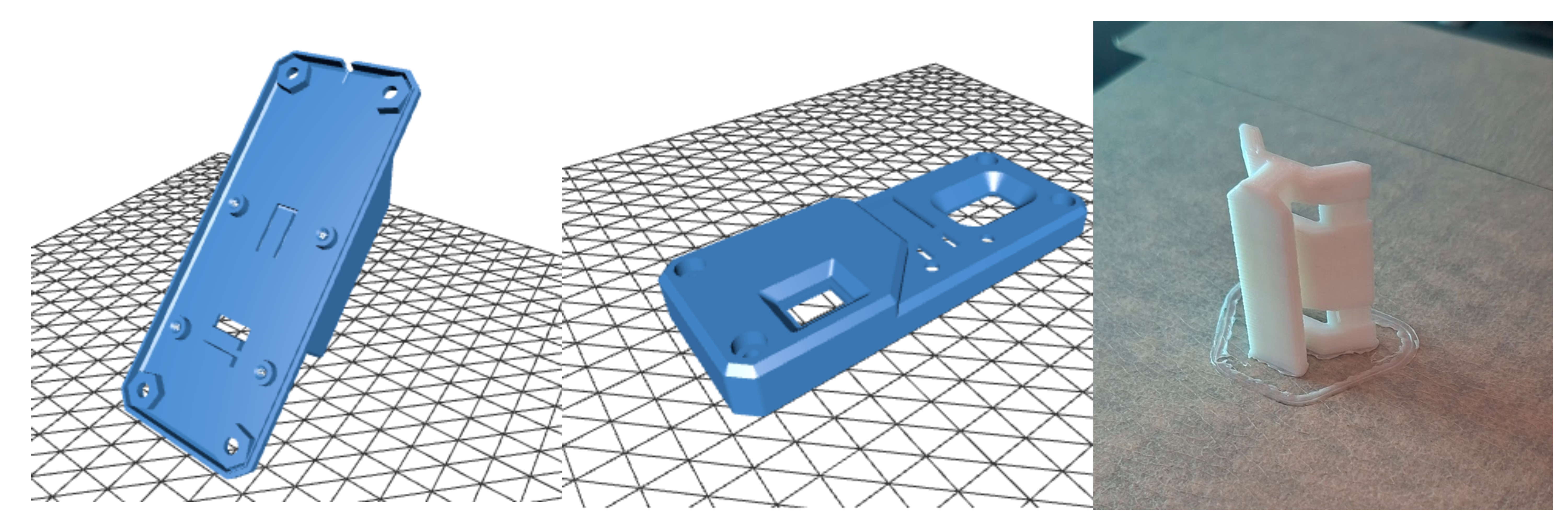
The result is a two-part enclosure with dedicated mounting adapters, designed specifically around the LPS node form factor:

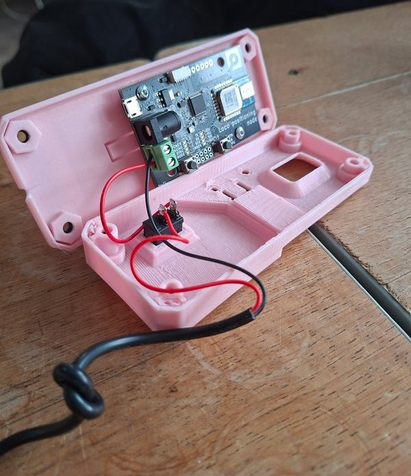
  • Front shell: Protective enclosure with power button
  • Back shell: Securely holds the LPS node PCB
  • Mounting adapters: Enable quick mounting on poles or tripods in vertical or horizontal orientation

Assembly Instructions

Place the back part as shown in the figure to print without supports. Rotate the front part by 180° relative to the figure to print without supports. The adapter should be printed standing upright.

Below are a few notes to get you started building the case:

  • Print all three parts and buy the additional off-the-shelf hardware components
  • Place the LPS node into the back part of the case.
  • Install the toggle switch and ensure correct orientation.
  • Connect and solder the USB power cable wires.
  • Lay down the USB cable on top of the designated notch in the back part (tie a small knot to release the tension).
  • Attach the front part and secure it with screws.
  • Use the adapter (“slider”) to mount the case on a tripod or pole (with cable ties, for example).
Make sure the red and black cables are wired correctly.

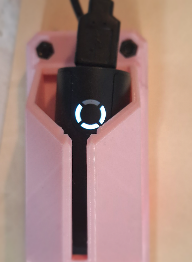
The USB power bank itself serves as the power indicator for the LPS node.

Evolution of the Case

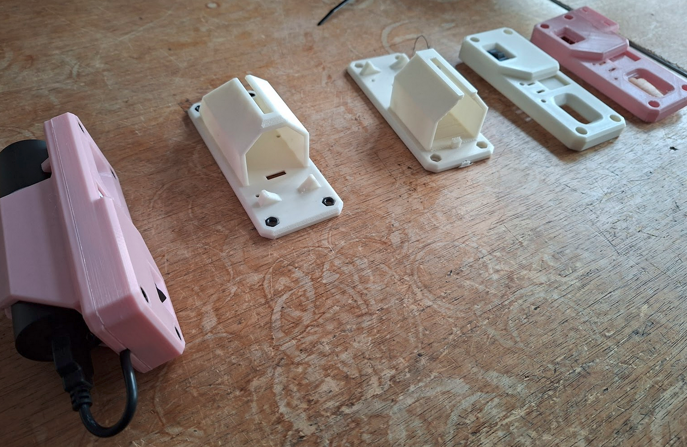
The design itself went through several iterations with adjustments.

In parallel, multiple design variations were explored to evaluate different approaches to mounting, cable routing, and overall form factor. Attention was paid to ensuring the parts print cleanly on common 3D printers without supports.

This process helped smooth out small usability issues and resulted in a design that is both easy to print and straightforward to use in practice.

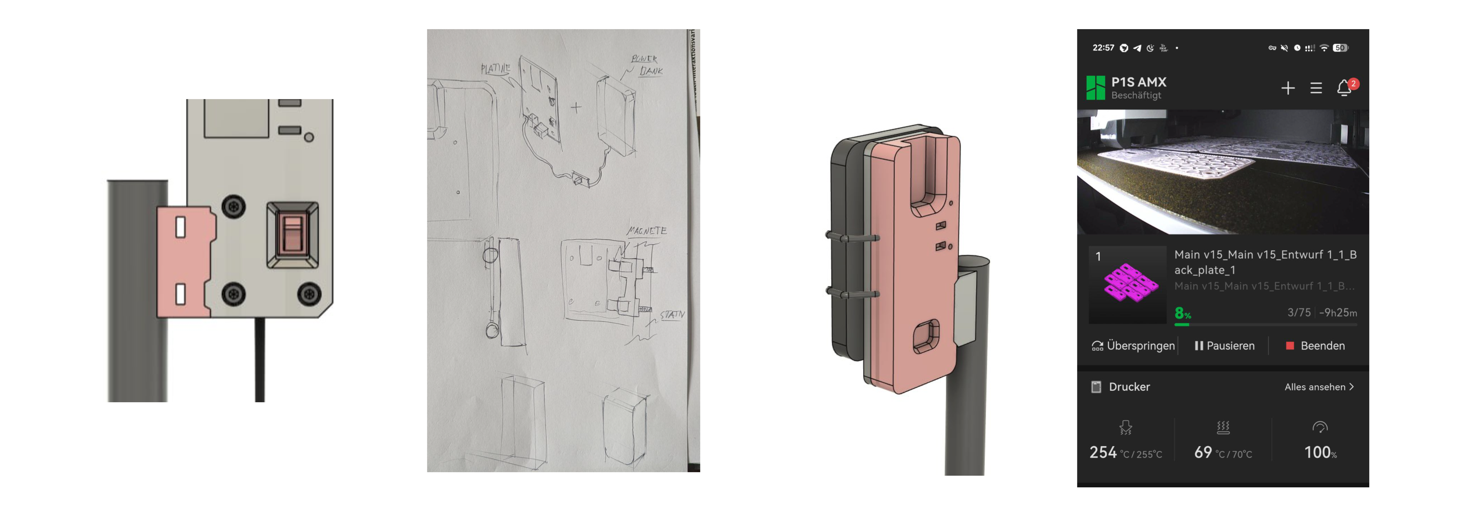
Vertical and Horizontal Mount Adapter

While the standard configuration mounts the enclosure vertically, a horizontal holder adapter has now been introduced. This provides additional flexibility depending on the experimental setup.

A short demonstration of the mounting system can be viewed here.

Conclusion

This enclosure and mounting system grew out of repeated practical use in changing indoor environments, and we hope it will be useful to others as well.

Feedback and ideas are always welcome. And by the way, if you print your own version, feel free to share photos of your setup!

Guest post by Dominik Grzelak, Dresden University of Technology, Germany

This blog post accompanies a research article published in the XR Salento 2025 proceedings (Springer LNCS).

Setting up a mobile indoor positioning system with the Crazyflie platform—specifically using the Loco Positioning System (LPS)—typically involves walking through a large room with a laser measure, sticky notes, and a bit of patience.

That was exactly my situation at work when setting up UWB anchors for mobile robot demonstrations, which often had to be relocated to different rooms.
And it got me thinking—what if there were a more intuitive, flexible way to define and deploy these setups, especially in labs or educational settings where reconfigurability is key?

This question led to the development of XR-PALS, a mixed reality tool that simplifies the entire LPS configuration process.
Instead of manually measuring anchor positions and inputting coordinates into cfclient, XR-PALS allows users to create and sync virtual and physical setups almost seamlessly—just by moving virtual anchors in space using a VR headset.

Diagram showing the three-step setup for the Bitcraze Loco Positioning System: 1) Connect anchors, 2) Configure the system, 3) Track the Crazyflie drone in 3D space.
Three-step setup process for the Bitcraze Loco Positioning System, illustrating anchor connection, system configuration, and 3D Crazyflie drone tracking.

What is XR-PALS?

XR-PALS (XR-Powered Assistance for Loco Positioning Systems) is a tool we (Victor Victor and Dominik Grzelak) developed for defining cyber-physical spaces using UWB anchors on tripods.
It runs on a passthrough VR headset (we used Meta Quest 3), allowing users to visualize the LPS layout and manipulate anchor placements in a virtual 3D environment until they are virtually and physically aligned.

Once everything is aligned, a single tap on the “Export” button sends the virtual anchor positions to a Rust-based middleware service running on a host machine within the same network as the VR headset.

It’s fast, visual, and eliminates the need for hand-measuring coordinates for our mobile robot demonstrators.

You can watch the system in action in our demo video:

Why We Built It

Usually, the LPS setup involves manual measurements and manual data entry in cfclient.
This is time-consuming when environments change frequently—as is often the case in education and research.

With XR-PALS, the goals are to:

  • Speed up setup – Users in our study completed setups significantly faster.
  • Reduce error – Anchor placement is visual and interactive. No calculations needed.

How It Works

XR-PALS consists of two main components:

  1. VR application
    Runs on a VR headset and displays the full anchor layout. Users can drag anchors, view distances, toggle info layers, and adjust alignment using natural hand gestures.
  2. Middleware service
    A Rust-based REST API that basically bridges the VR app with the LPS anchors. This service receives the coordinates and remotely updates the LPS anchors—enabled by the open-source nature of the LPS firmware: bitcraze/lps-node-firmware. Coordinates are exported as YAML that can be imported by cfclient.
Diagram showing the system architecture for the XR PALS setup, including UWB anchors, Crazyflie drone, tracking system, and XR interface components connected through data and control flows.
System architecture.
Images of XR PALS user interactions, showing a person wearing an XR headset controlling a Crazyflie drone in a physical space with visual overlays and positional feedback.
User interactions.

Real-World Evaluation

We compared XR-PALS against a traditional laser measurement tool in a user study involving 18 participants from our Faculty of Computer Science.
Each participant had to configure a LPS layout (trapezoidal or rectangular) using one of the two tools.

Results:

  • XR-PALS users completed the task faster
  • Fewer measurement errors
  • Higher usability scores and confidence
  • Lower cognitive load, especially for the trapezoidal layout
Bar chart comparing average task completion times for XR-PALS and laser methods, showing XR-PALS with shorter times. Lower values indicate better performance.
Bar chart comparing task completion times between XR-PALS and laser. Lower values are better.
Bar chart comparing average measurement errors for XR-PALS and laser methods, showing XR-PALS with lower errors. Lower values indicate better accuracy.
Measurement error comparison between XR-PALS and Laser. Lower values are better.

The minimal loss in accuracy compared to the time saved is not dramatic for our use cases, compared to the time saved—especially when more participants were able to correctly determine the coordinates overall.
In general, users were more confident using VR glasses than a laser measurement device.

Summary and What’s Next

So if you’re working with dynamic robot setups or swarm experiments, XR-PALS might save you a lot of setup time.

The app works natively with the Bitcraze Loco Positioning System and, so to speak, extends the capabilities of the cfclient.

Here’s what we’re currently thinking about:

  • Supporting larger anchor sets within the app (currently limited to 8 anchors)
  • Improving user interactions based on feedback from our user study
  • Displaying anchor diagnostics (e.g., latency, power levels)
  • Simpler layout reusability (layouts can be saved and shared only via the computer)
  • Adding support for LPS-ROS
  • Releasing the Code here
  • Better casing and docking solutions for the nodes (3D printing)

Check out the project page for updates—and feel free to reach out if you’d like to share how you’re using the LPS.