Some Fun-Friday projects begin with a clear goal and a straight path to the finish line. The best ones, however, take you somewhere completely unexpected.
This project originally set out to build a device for determining spatial coordinates within a Lighthouse-covered flight area. Instead, it evolved into the Lighthouse Wand, a hand-held “magic wand” letting you grab and move drones in 3D space just by pointing at them.
How it works
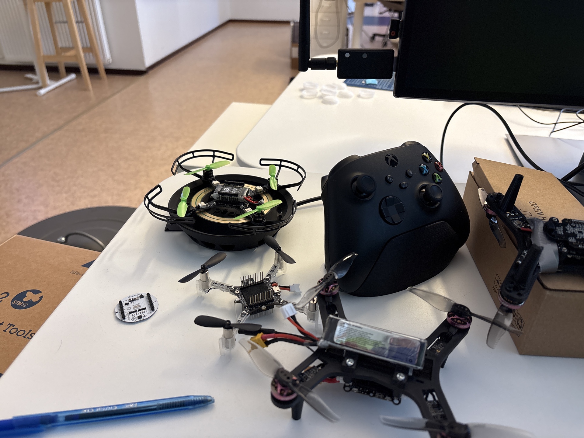
The Wand is a Crazyflie platform with a Lighthouse positioning deck. That’s enough for it to know its own position and orientation in the room. When the button is pressed, it starts broadcasting those 6 numbers over Peer to Peer radio.
Any Crazyflie/receiver in the room on the same radio channel, listens to those packets and runs a simple “grasping” algorithm: while the wand line (positive x-axis) passes close enough to the drone, it builds up a confidence score. Once the score crosses a threshold, the drone is considered grasped. From that point on, it just keeps a specific distance from the wand, while being on the wand line.
When the button is released, the grasped drone either hovers in place, or lands, depending on the release height.
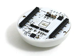
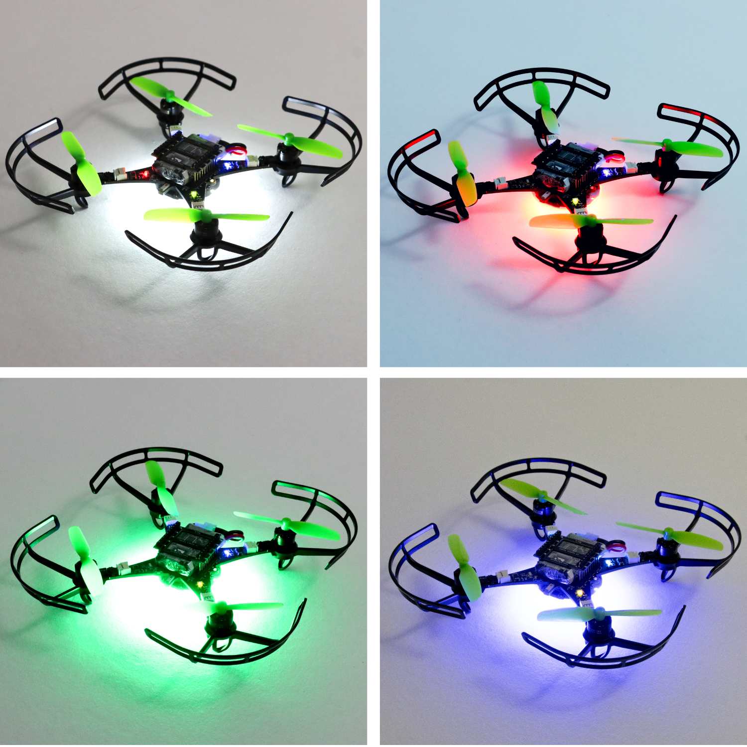
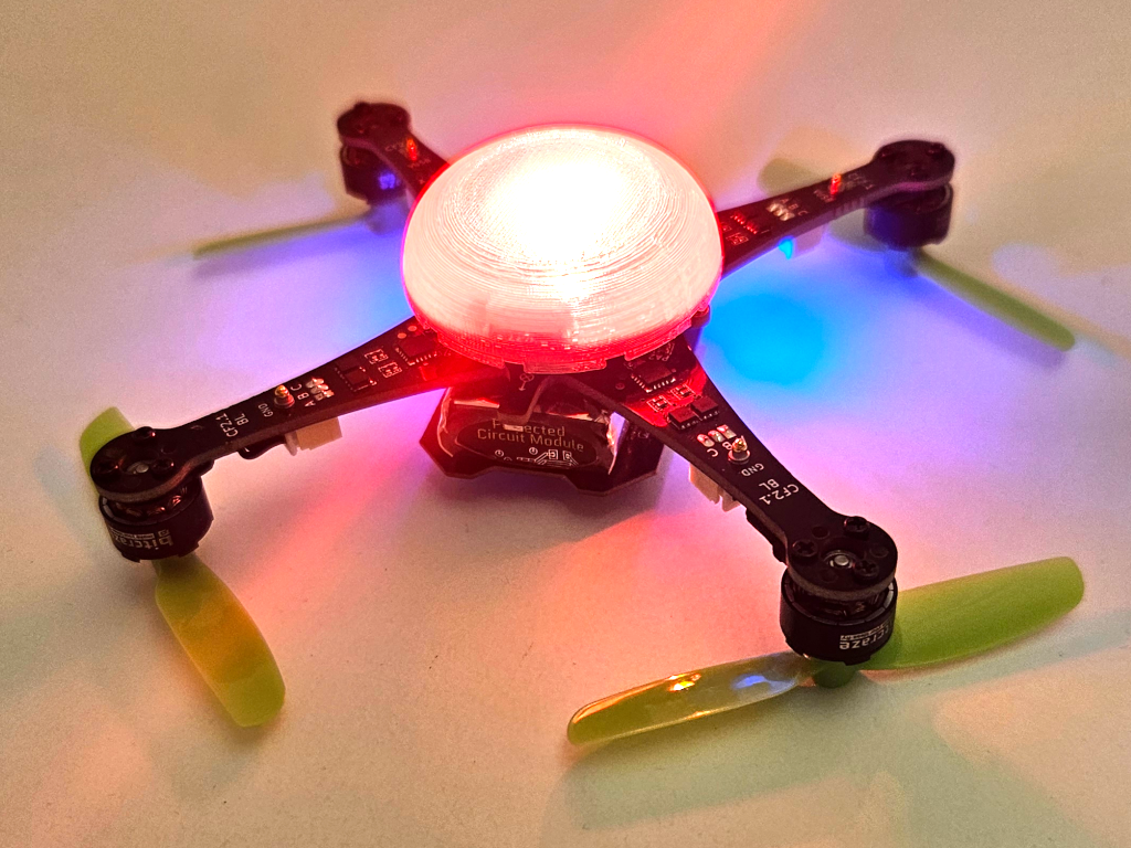
The Color LED deck on the receiver drone, gives you visual feedback: yellow while the Crazyflie is building up its confidence score, green when it’s grasped, and red when it’s landing.
A big advantage of this system is that all interactions run entirely onboard the Crazyflies, allowing them to operate without relying on the cfclient or cflib during flight.
The hardware design
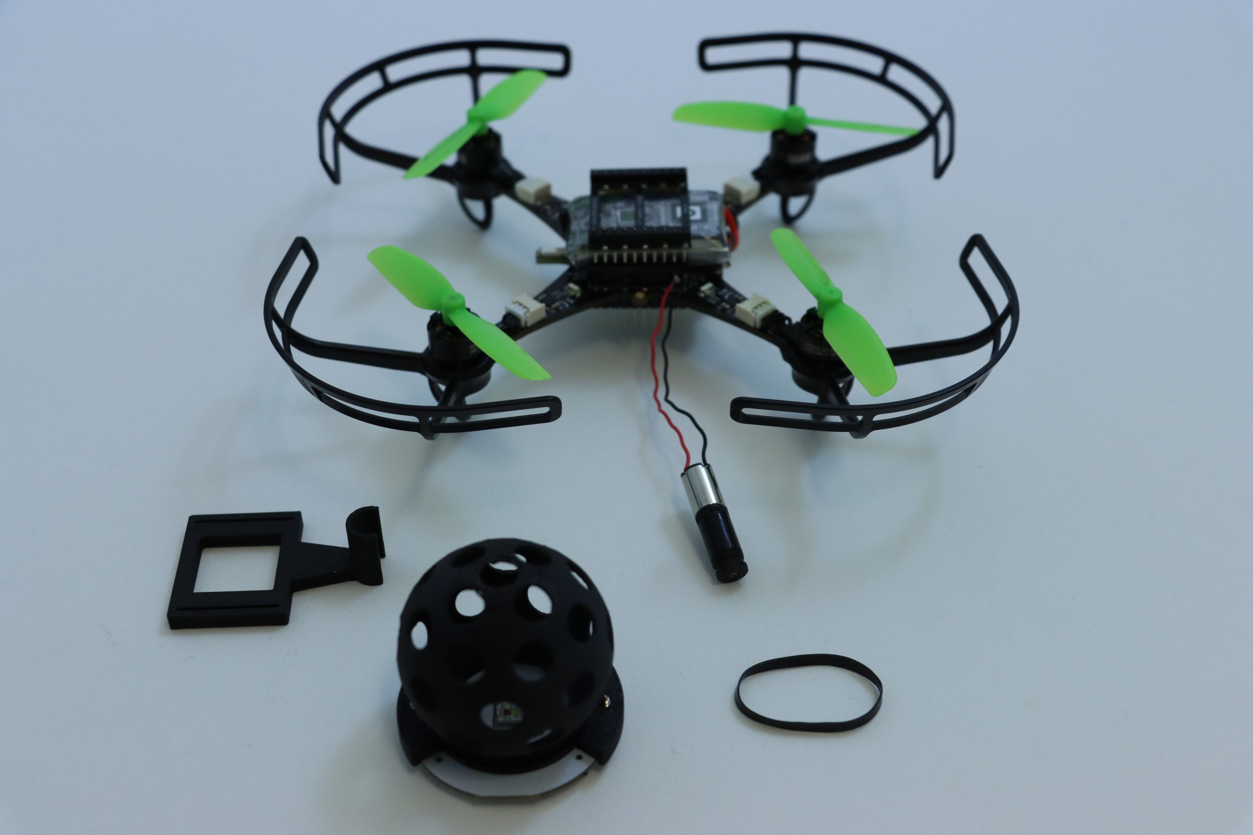
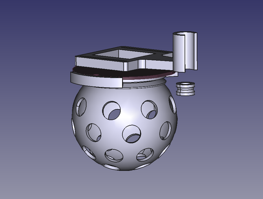
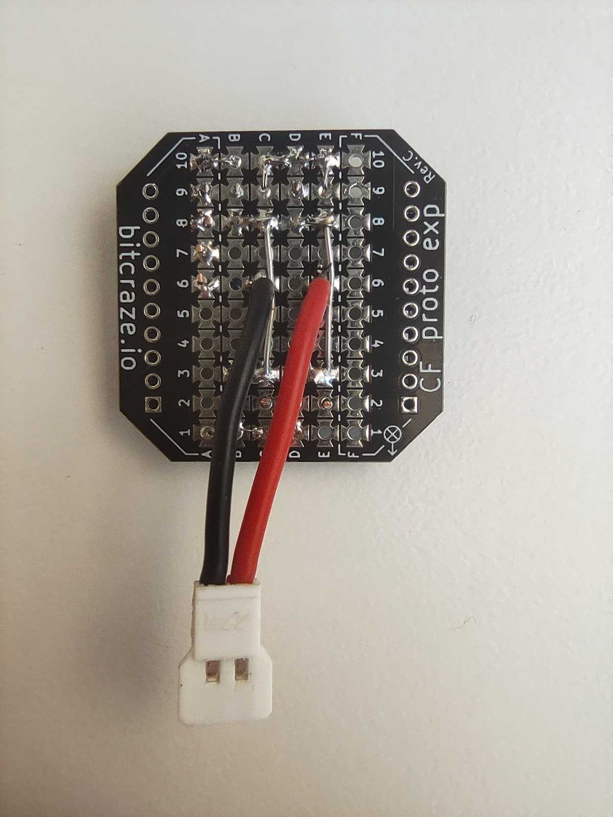
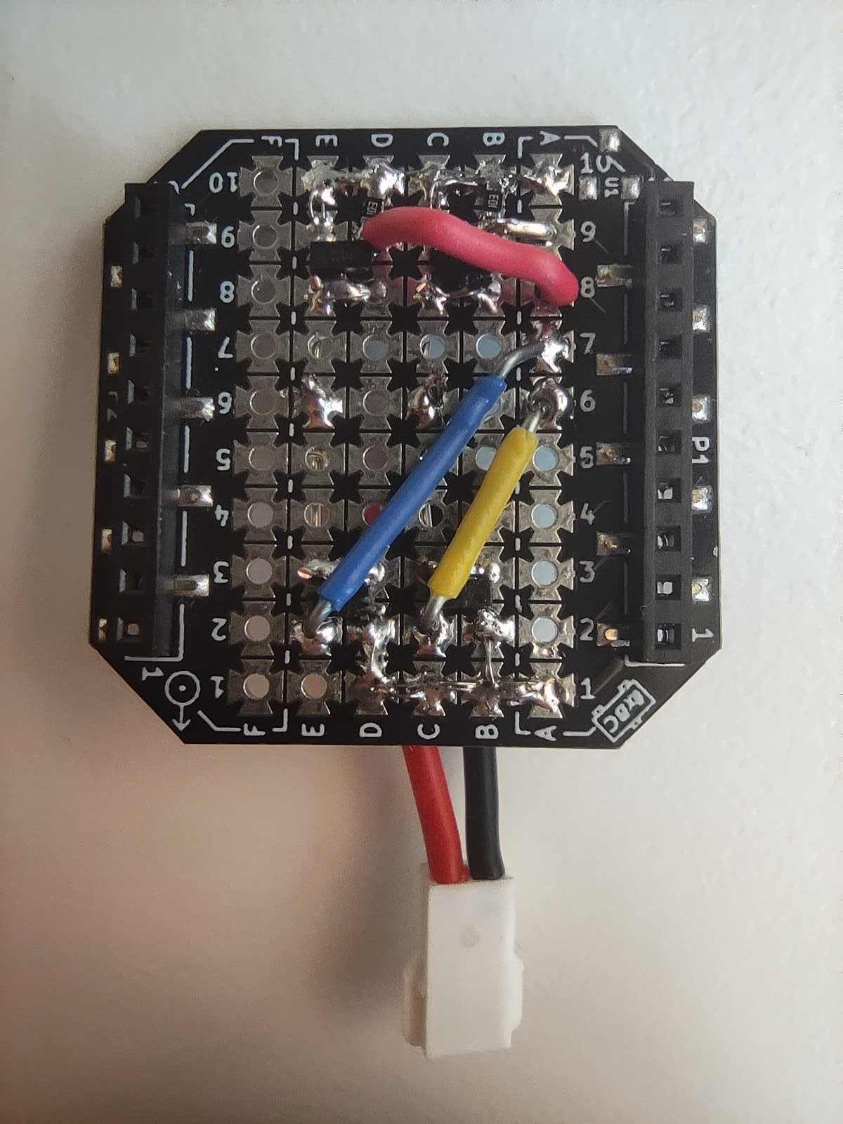
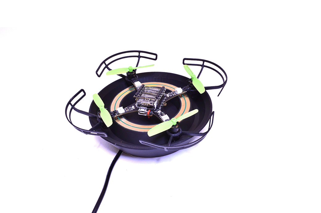
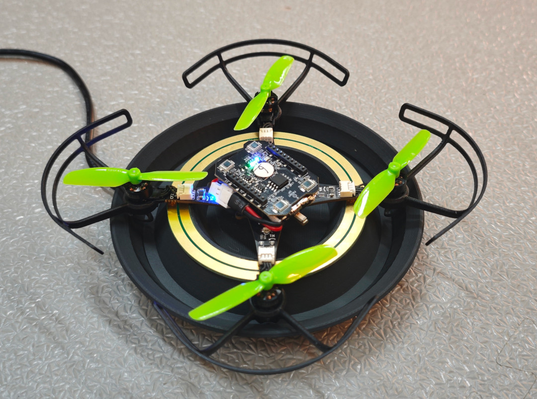
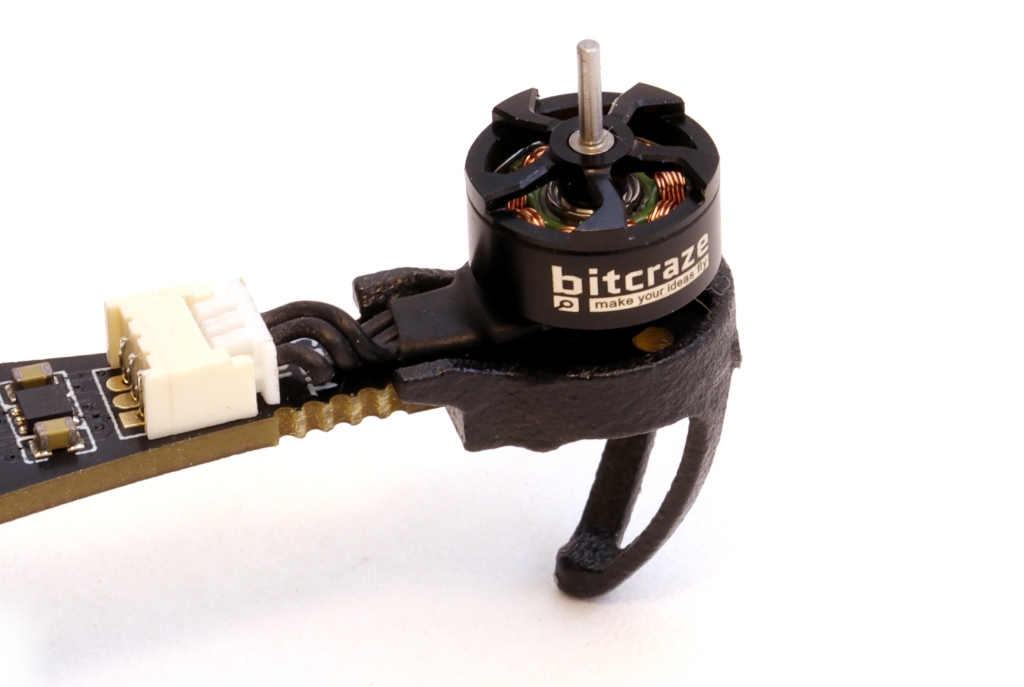
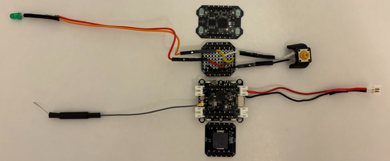
The wand is a Crazyflie Bolt 1.1 with a Lighthouse positioning deck and a Buzzer deck for audio feedback. To allow for user input, I created a simple “Button deck” based on the Prototyping deck utilizing the GPIO pins of the Crazyflie. It also includes an LED for visual feedback when the button is pressed.
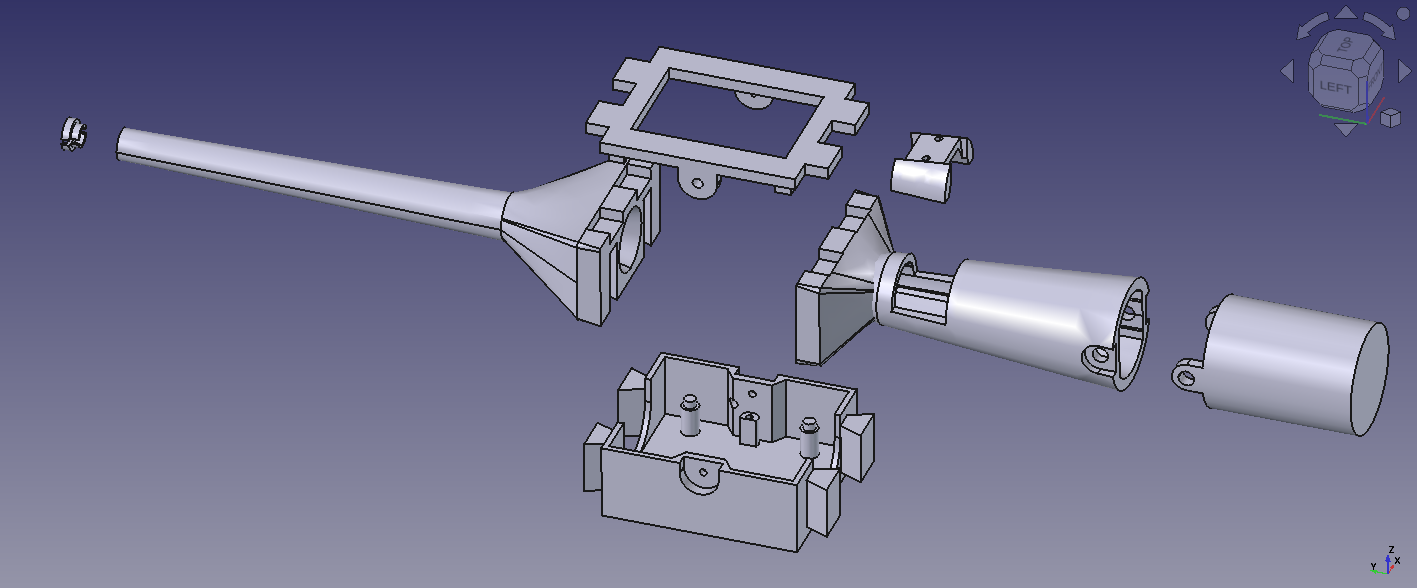
The casing is fully 3D printed in PLA and was designed to give the device a more wand-like feel in the hand. Its shape also makes it easier to hold, aim, and use intuitively during interaction.
The firmware design
Both the Wand and the receiver are firmware apps created on top of the crazyflie-firmware. In the design that I followed, there is a clean separation between the two parties. The wand is a pure broadcaster: it only reads its own pose and transmits it. All grasping logic and flight control run independently on each receiver. Since each receiver is fully autonomous, the system scales to any number of drones with no extra load on the wand.
Where to find the Lighthouse Wand?
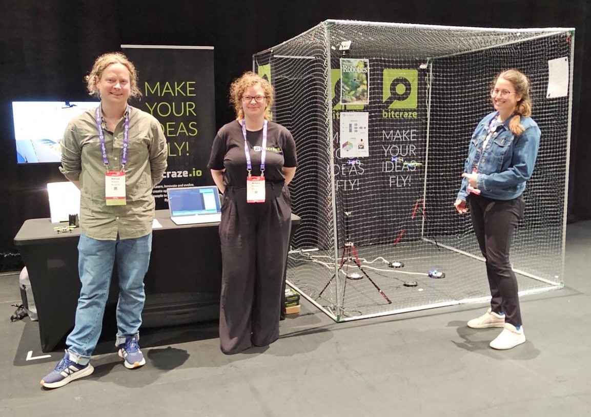
A version of the Lighthouse wand is now integrated in our decentralized swarm demo, where it can be used to interact with multiple drones, while the collision avoidance algorithms are still on. This system was first showcased at the European Robotics Forum 2026 in Stavanger, and we’ll also be bringing it to ICRA 2026. If you’re there, stop by booth 91and try flying a bunch of Crazyflies yourself using the wand.
You can find the complete Lighthouse Wand project in this repository. It contains the firmware, the hardware files, and detailed documentation to build and experiment with the wand yourself.