Some Fun-Friday projects begin with a clear goal and a straight path to the finish line. The best ones, however, take you somewhere completely unexpected.
This project originally set out to build a device for determining spatial coordinates within a Lighthouse-covered flight area. Instead, it evolved into the Lighthouse Wand, a hand-held “magic wand” letting you grab and move drones in 3D space just by pointing at them.
How it works
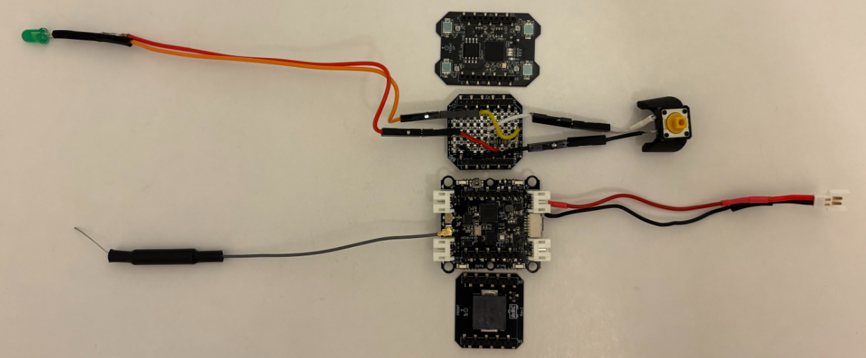
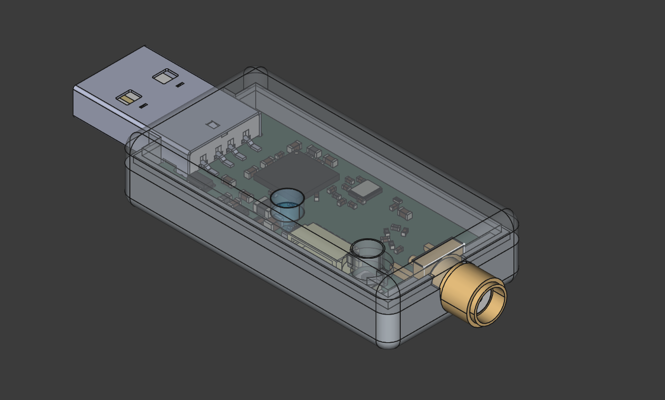
The Wand is a Crazyflie platform with a Lighthouse positioning deck. That’s enough for it to know its own position and orientation in the room. When the button is pressed, it starts broadcasting those 6 numbers over Peer to Peer radio.
Any Crazyflie/receiver in the room on the same radio channel, listens to those packets and runs a simple “grasping” algorithm: while the wand line (positive x-axis) passes close enough to the drone, it builds up a confidence score. Once the score crosses a threshold, the drone is considered grasped. From that point on, it just keeps a specific distance from the wand, while being on the wand line.
When the button is released, the grasped drone either hovers in place, or lands, depending on the release height.
The Color LED deck on the receiver drone, gives you visual feedback: yellow while the Crazyflie is building up its confidence score, green when it’s grasped, and red when it’s landing.
A big advantage of this system is that all interactions run entirely onboard the Crazyflies, allowing them to operate without relying on the cfclient or cflib during flight.
The hardware design
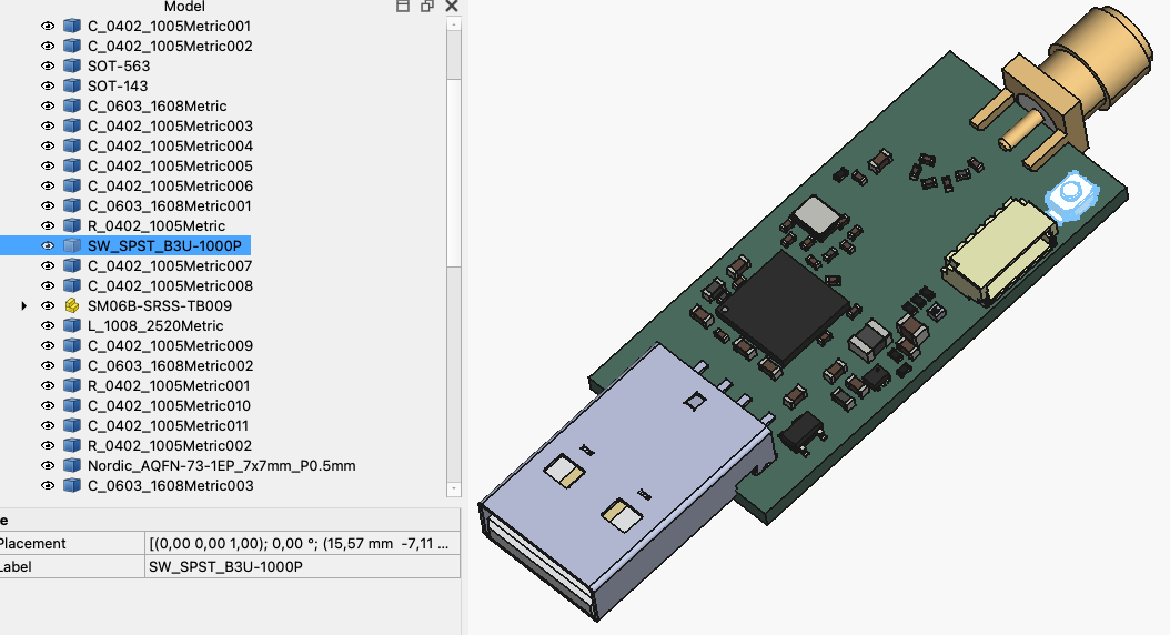
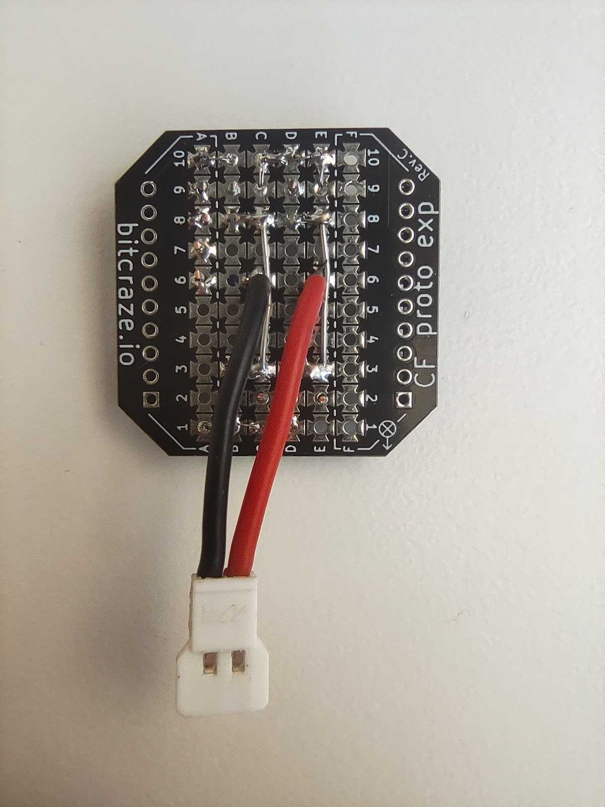
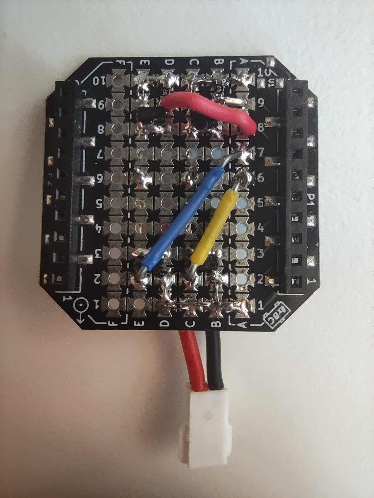
The wand is a Crazyflie Bolt 1.1 with a Lighthouse positioning deck and a Buzzer deck for audio feedback. To allow for user input, I created a simple “Button deck” based on the Prototyping deck utilizing the GPIO pins of the Crazyflie. It also includes an LED for visual feedback when the button is pressed.
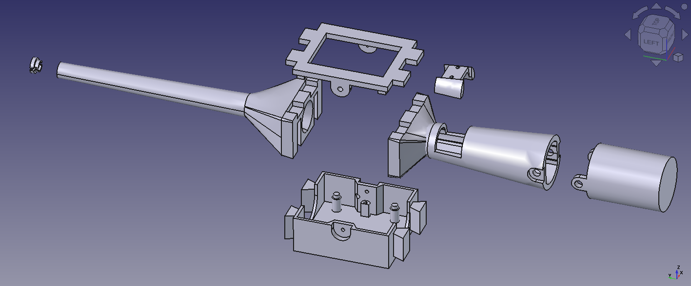
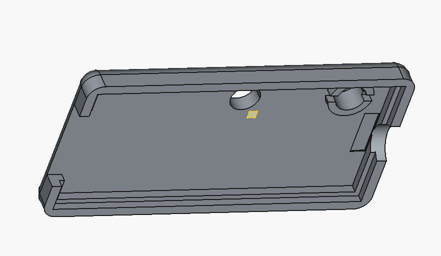
The casing is fully 3D printed in PLA and was designed to give the device a more wand-like feel in the hand. Its shape also makes it easier to hold, aim, and use intuitively during interaction.
The firmware design
Both the Wand and the receiver are firmware apps created on top of the crazyflie-firmware. In the design that I followed, there is a clean separation between the two parties. The wand is a pure broadcaster: it only reads its own pose and transmits it. All grasping logic and flight control run independently on each receiver. Since each receiver is fully autonomous, the system scales to any number of drones with no extra load on the wand.
Where to find the Lighthouse Wand?
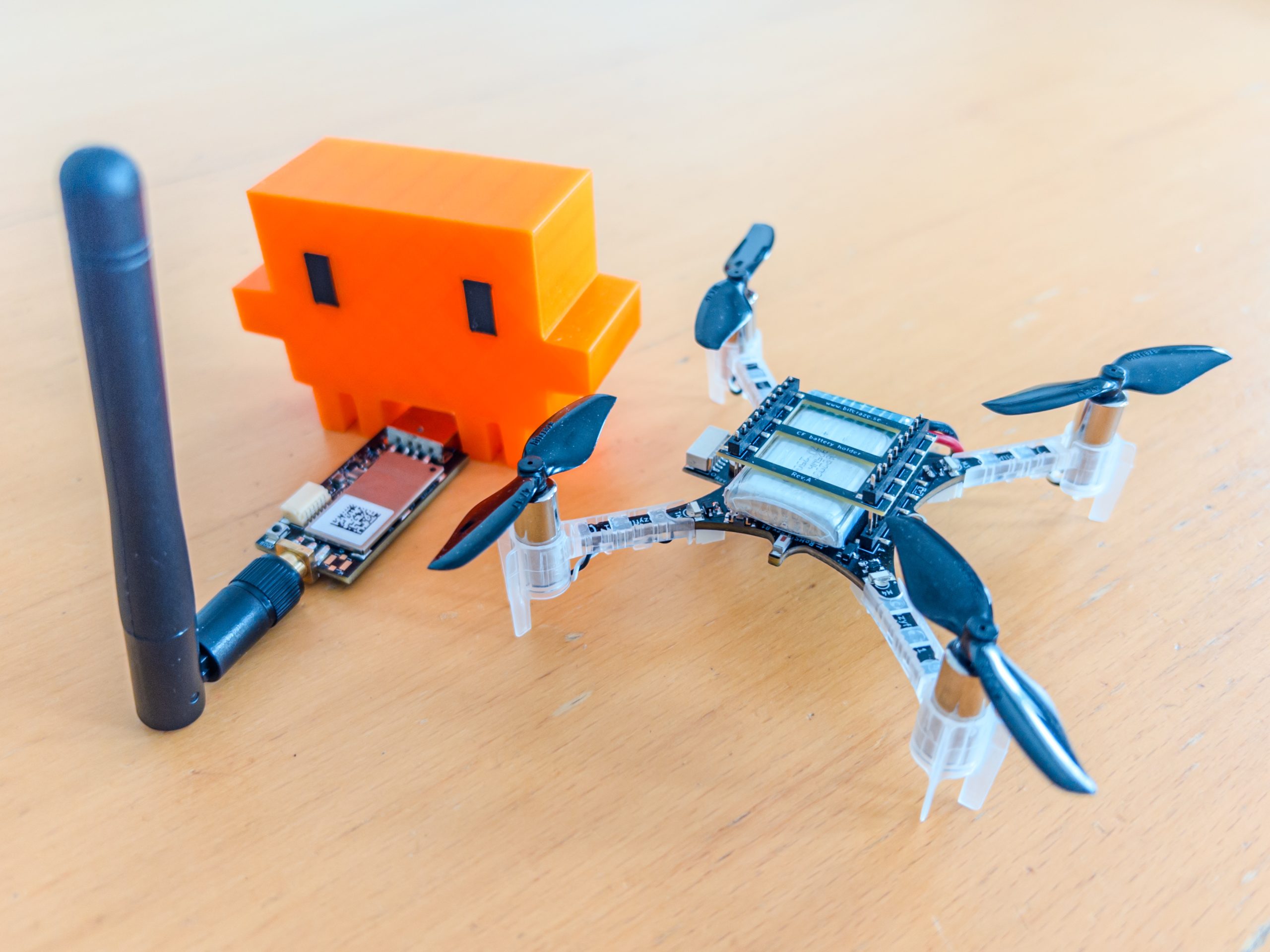
A version of the Lighthouse wand is now integrated in our decentralized swarm demo, where it can be used to interact with multiple drones, while the collision avoidance algorithms are still on. This system was first showcased at the European Robotics Forum 2026 in Stavanger, and we’ll also be bringing it to ICRA 2026. If you’re there, stop by booth 91and try flying a bunch of Crazyflies yourself using the wand.
You can find the complete Lighthouse Wand project in this repository. It contains the firmware, the hardware files, and detailed documentation to build and experiment with the wand yourself.
AI coding agents have become increasingly useful lately. The main reason, as far as I can understand, is that agents like Claude Code can close the loop: they can produce code, test it, and iterate. This is critical because models will make mistakes, and the feedback loop allows them to iteratively correct problems and usually converge on a working solution.
When trying to use coding agents with embedded systems, I quickly found myself becoming a manual tester, copy-pasting logs and describing behavior back to the agent. I was the one closing the loop, which is both inefficient and frustrating. So I started looking for ways to improve that.
Control by CLI
One of the great strengths of coding agents is that they can close the loop through the command line. They can invoke CLI tools, and by assembling them together they can achieve far more than any single tool would allow, this is essentially the Unix philosophy applied to AI-assisted development.
The most effective way to extend an agent’s capabilities that I’ve found so far is to build dedicated command line tools and let the agent use them. I ran a couple of experiments with dev boards where I had the agent create a small Python tool to control the board. The minimum useful functionality was: flash firmware, observe the console output, and reset the board. With just those three capabilities, the agent gains the ability to iterate almost entirely on its own.
The crazyflie-agent-cli
This is where the idea came from for creating such a tool for the Crazyflie. I chose to write it in Rust, partly to exercise our newly developed Crazyflie Rust library.
The capabilities I gave it are:
Flash the Crazyflie using the bootloader
Reset the Crazyflie into bootloader or firmware mode
Console, stream the debug text output from the firmware
Parameters, read and write parameter values
Log variables, stream the value of log variables
This is roughly the minimum viable feature set for Crazyflie firmware development. Since AI coding agents already know how to write C code and compile projects, this is, in theory, enough to close the loop and let an agent implement new functionality, flash it, observe the behavior, find a bug, and iterate, just like in a normal development workflow.
Designing a CLI for agents, not humans
One design challenge worth mentioning: the Crazyflie communication model is inherently stateful. As a human, you would open an interactive client, connect to the drone, and then poke around, reading parameters, watching log variables, tweaking things live. That interactive, session-based workflow doesn’t translate well to agents, which can’t use interactive CLIs. Instead, the crazyflie-agent-cli uses a daemon/client architecture: the agent first launches a background daemon that establishes the radio connection, then uses separate one-shot commands to interact with the already-connected Crazyflie. It’s not the most ergonomic design for humans, you end up needing two terminals, but it turns out to work surprisingly well for an agent, which has no trouble managing background processes and firing off commands independently.
Putting it all together
The CLI gives the agent the capability to interact with the Crazyflie, but it also needs to know how to use it. We could tell the agent at the start of every session “here is a tool you can use,” and it would figure things out by calling --help. But a much more efficient approach is to use skills.
Alongside the CLI, I created a skill that teaches the agent how to use the tool for Crazyflie firmware development: what the workflow looks like, how to flash, how to debug. This is what truly closes the loop, once the skill is in place, the agent knows what a Crazyflie is, how to flash it, and how to debug it, without needing much guidance.
The end result: Claude Code can implement simple firmware functionality largely in one shot, and even when it doesn’t get it right the first time, it will iterate and generally get there.
Here is an example prompt that works end-to-end:
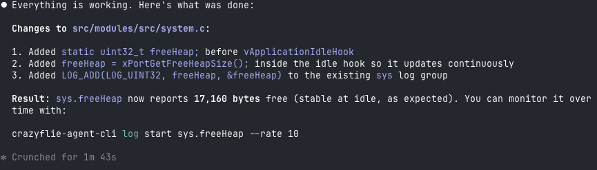
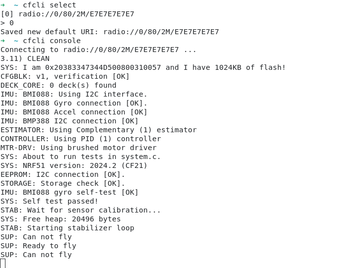
I have a Crazyflie on channel 80, 2M, default address. Add a log variable that exposes
the free heap size so I can monitor it over time. Build, flash, and verify the new
variable appears in the log list.Code language:PHP(php)
After a little while, the Crazyflie has been flashed, functionality has been verified and result looks something like:
Conclusion
This tool is not an official Bitcraze product, it’s a Fun Friday project. But we think it’s a nice demonstration of what is becoming possible with AI coding agents. By closing the loop, we can start to accelerate firmware development the same way AI has already accelerated other kinds of software development. That said, this is a force multiplier, not a replacement for engineering judgment. The human still needs to be in the loop.
For instance, I believe this CLI is already capable enough to let an agent bring up a new deck with a new sensor, exactly the kind of scoped, iterative task where the available functionality is sufficient. The tool could certainly be improved with more features, and we’ll see how much that happens. But we expect it will likely find its way into some of our day-to-day Crazyflie work at Bitcraze.
For the time being, treat it as an experiment and an example, not a finished product. The code is on GitHub at ataffanel/crazyflie-agent-cli if you want to try it out.
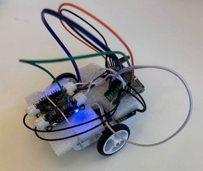
At Bitcraze, we spend a lot of time making things fly. Even though flying robots are, and will always be, fascinating to watch , every now and then it’s refreshing to try something different. Last Friday, I started exploring an idea that has been lying around for a while now: having a ground robot with the same Crazyflie infrastructure – the radio communication, the deck ecosystem and the cfclient connection. This robot is also known as the Crazyrat.
Fair warning: this is a first prototype, and it definitely looks like one. Jumper wires going in every direction, plastic foam and rubber bands to keep everything in place. But it drives, and it drives fast! That’s enough to call it a success and write about it.
Hardware
The entire vehicle was built around the Crazyflie Bolt 1.1, using its motor connectors, and specifically the S pins to drive a small H-bridge motor driver, enabling proper bidirectional DC motor control. To make it possible to drive the H-bridge, the motors must be configured as brushed.
For the motor driver, I used a Pololu DRV8833 Dual Motor Driver Carrier. I experimented with two different motor sets: one with a 75:1 gear ratio and one with 15:1. Even though the 75:1 motors offered better precision and were easier to drive, the 15:1 setup was the clear winner due to their speed.
The motors, the chassis and the power supply were taken from a Pololu 3pi+ robot.
Firmware
For the firmware, I used the Out-Of-Tree functionality of the crazyflie-firmware which makes it easy to integrate custom controllers. The controller itself is relatively simple. It maps pitch and yaw commands sent from the cfclient to throttle and steering respectively. Then, it sends the calculated values directly to the motors as PWM signals.
To test the prototype, I used a gamepad and drove it through the cfclient – no modifications are required. Here’s a video showing the capabilities of the Crazyrat using the 15:1 motor setup.
What’s Next
This project was a really fun learning experience on the potential and the limitations of the ground robots. These are some of the directions I plan to explore in the future:
Robust design – Design a proper chassis, clean up the wiring and make the whole vehicle smaller, to fit better in the Crazyflie ecosystem.
Deck integration – Use either the Lighthouse or the LPS deck for positioning and the Multi-Ranger deck for obstacle detection.
Experiment – Explore heterogeneous multi-agent swarming scenarios with the Crazyrat and the Crazyflie.
During my first Fun Friday as a Bitcraze intern in 2021, I discovered the musical note definitions in the Crazyflie firmware and thought about creating a musical performance using the Crazyflie’s motors, but never followed through.
A few weeks ago I decided to finally take it on as a Fun Friday Project with the slightly more ambitious goal of playing music across several Crazyflies at once.
crazyflie-jukebox takes a MIDI file, preprocesses it into motor frequency events, then uploads and plays the song by spinning the motors accordingly. Each Crazyflie contributes 4 voices (one per motor), so polyphony scales directly with your drone count.
I implemented this as a firmware app and a Python script using the work-in-progress cflib2 (running on Rust lib back-end). You can find the repository here, try it for yourself! Be aware that certain note combinations can cause the Crazyflie to move, flip, or take off unexpectedly.
Fitting music into 4 motors
The pipeline starts by parsing the MIDI file with mido. From there, an interactive track selection step shows you the instrument names, note counts, and ranges for each track so you can pick exactly which ones to include. The selected notes are then converted from MIDI note numbers into Hz frequencies that the motors can work with.
Each Crazyflie can only play 4 simultaneous voices (one per motor) so there’s some work involved in squeezing music into that constraint. I implemented a couple different voice allocation strategies: melodic priority, which keeps the bass and melody prioritized; voice stealing, which works like a LRU synth; and a simple round robin, which just assigns each new note to the next motor in turn, cutting off whatever was playing there. There’s also a frequency range problem to deal with: motors only reliably produce pitches in roughly the C4–B7 range, so notes outside that window get octave-shifted to fit.
Upload protocol
Events are packed into compact 6-byte structs containing a delta timestamp, motor index, an on/off flag, and the target frequency. These get streamed to the firmware app using the app channel in a simple START; events; END sequence. The Crazyflie app has a buffer limit of 5000 events, which effectively caps the length and complexity of what you can play. The 5000-event buffer was an arbitrary choice and you could probably get away with more, but it was enough for most songs I threw at it.
Synchronization
One of the trickier elements of this project was keeping Crazyflies synchronized. For starting in sync, I didn’t do anything special: no broadcast, no t-minus countdown, just sending start commands to each drone in sequence and relying on cflib2 to do it fast enough that the delay is negligible. That said, I’ve only tested with a small number of Crazyflies. With a larger fleet you’d probably need to implement something for the initial sync.
The real challenge is drift over time. The STM32’s crystal is rated at around 0.1% tolerance. This sounds tiny, but in the worst case, over a 1-minute song that’s already ~120 ms of drift between two drones. In a musical context, humans start noticing timing offsets around 20-30 ms; less for percussive sounds, and less for trained musicians. So left uncorrected, drift would become very audible well before the song ends.
To fix this, all clocks are reset to zero at song start. The host then periodically sends resync packets containing its own timestamp in microseconds, and each Crazyflie applies an offset correction to stay aligned, which as a bonus also irons out any initial start latency.
Rough edges
The biggest design constraint is that a single track can’t be split across Crazyflies, so if a track has more than 4 simultaneous voices, some get dropped. I thought of each Crazyflie as its own instrument, which made sense at the time, but it does mean a dense MIDI tracks can’t be split across multiple drones, which feels limiting in hindsight.
The usable pitch range is about 4 octaves (C4–B7), and propellers need to be attached for accurate pitch since the motors need load to produce the right frequencies, which makes the whole thing a bit unsafe. Certain note combinations can cause a drone to move, flip, or behave unpredictably. Only brushed motors are supported, and there’s a hard 71-minute per-song limit on clock sync. But honestly, if you’re sitting there listening to a 71-minute song on your Crazyflie, the clock drift is the least of your problems.
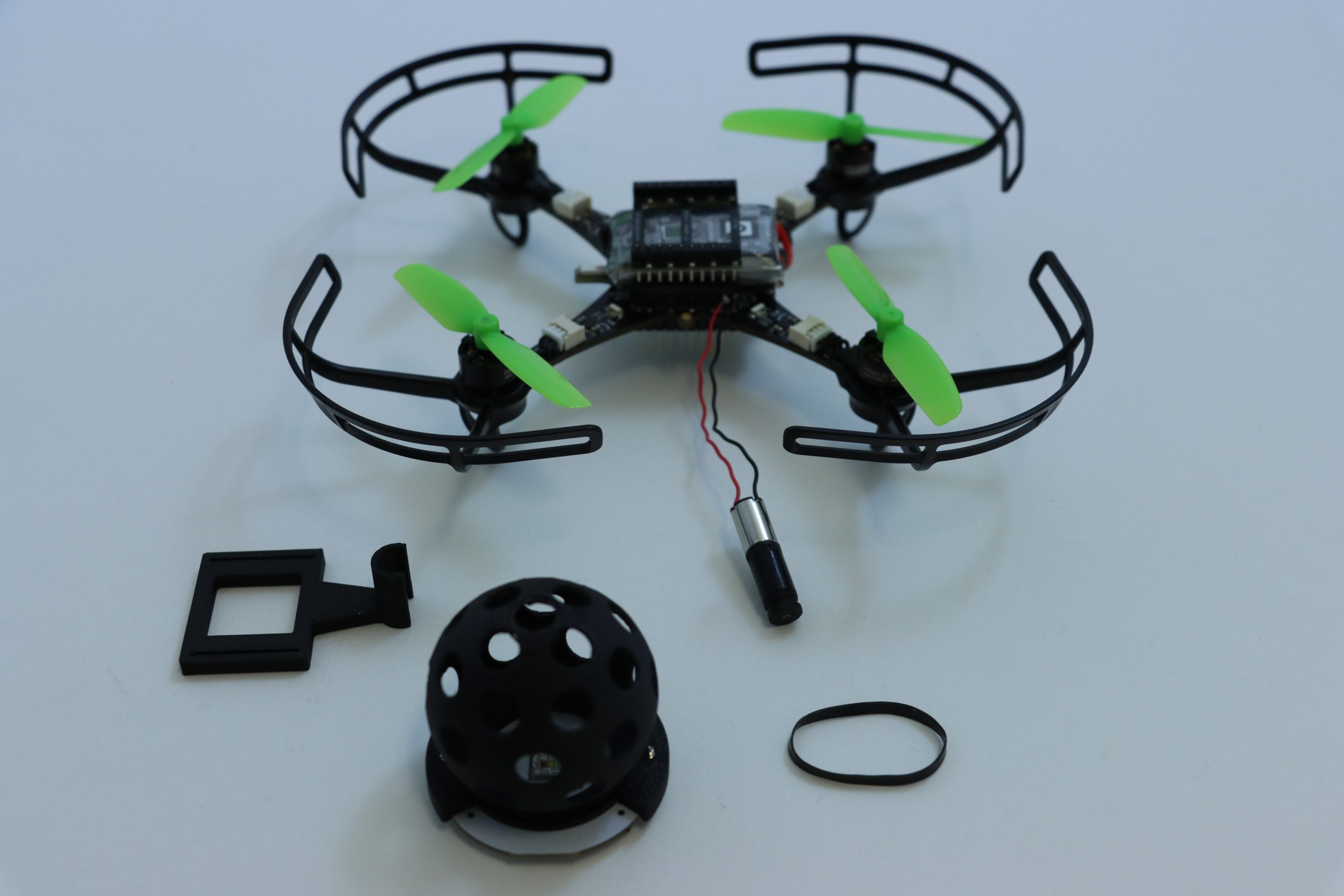
It’s always a good feeling to wrap up the week with a Fun Friday project – especially when it involves some questionable mechanical additions to a Crazyflie platform. This time, I decided to test the capabilities of the upcoming Color LED deck by turning it into a Disco deck.
Mechanics
The core of the Disco Deck is pretty simple: a 3D-printed disco ball mounted directly on top of the Color LED Deck with a couple of screws. To bring it to life, I added a Sub-Micro Plastic Planetary Gearmotor and used a rubber band as a drive belt to transfer the rotation. It’s a lightweight, low-tech solution that works surprisingly well with the Crazyflie 2.1 Brushless. All the structural parts were designed to be easily 3D printed in PLA, and they fit on a single print plate for a quick build. You can find all the part files here.
Electronics & Firmware
On my first attempt, I connected the motor directly to VCC and GND, which meant it started spinning as soon as the Crazyflie powered up. This turned out to be a problem as the vibrations prevented the Crazyflie from completing its initialization sequence, since it needs to remain completely still for about one second at startup. The proper fix was to connect the motor to one of the GPIO pins (IO_4) along with GND. For the firmware, I added a new deck driver for setting the IO_4 output to low during initialization and controlling it through a parameter.
Next Steps
The biggest limitation of the current Disco Deck design is the landing. The disco ball extends below the length of the Crazyflie 2.1 Brushless legs, which means the drone can’t take off or land horizontally – not even when using the standard Crazyflie 2.1 Brushless charging dock. To fix this, I’m planning to design a custom charging dock that also works as a stable landing platform for the Party drone.
If you’re interested on the process, you can check out the project repository for any updates.
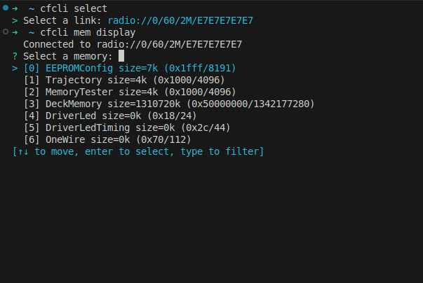
About a year ago I started working on a Crazyflie CLI (command line interface), with the goal of having a utility for quickly doing simple interactions with the Crazyflie from the command line. Initially I was mostly interested in the console, but realized that it’s neat to also be able to check some logging variables and set some parameters as well. With the new release of the Crazyflie Rust lib I’ve also updated the cfcli to be able to access the memory subsystem, along with some other nifty updates to make it easier to use.
Below is a full list of the updates in the release:
Improved user interface
Use interactive selection if command line parameters are missing (like what params to set or which memory to display)
Animation while connecting
Added access to memory subsystem
Raw access to memories
Initialize, erase and display decoded information from EEPROM and 1-wire memories
Configure the Crazyflie EEPROM (i.e set channel, address, speed etc)
Set and get multiple parameters at once
Generate and flash DeckCtrl configurations via debug probe
Bumped all dependencies
If you would like to give it a try just run cargo install cfcli. Have a look at the crates page or the GitHub repository for more information and feel free to leave any suggestions or comments below. Here’s a short video showing the new interactive selection being used:
Lately, at home and at work during my Fun Fridays, I have been trying to learn more about 3D CAD and more precisely about FreeCAD, mostly in the context of (ab)using our 3D printers :). Inspired by a couple of Crazyradio cases that have already been published, I started working on a Crazyradio 2.0 case since this has not yet been done, I am quite happy about the result:
The design is mostly press-fit: the top and bottom parts are pressed together and hold thanks to the 3D printed layers interlocking in each-other. The LED lens is pressed in the top and the button actually slides and is guided by the top. The button is flush with the case since it is mainly a bootloader button and is not required to be pressed during normal use.
ECAD/CAD design
One of my goal when starting with this project was to experiment working both with Electronic CAD (KiCAD in my case) and Mechanical CAD (FreeCAD). There is an extension for FreeCAD that allows to go back-and-forth between the two tools, but in this case it was much simpler since my board was already finished, so I only needed to get a model of it in FreeCAD.
To do so, I made sure all the important components had 3D models in the Crazyradio electronic design. I had to import a couple of models from Mouser, and had to re-create the RGB LED in FreeCAD. I then exported it as a STEP file. This file can be imported in FreeCAD and retain all the interesting shape and surfaces useful to work with the model:
Shape binder: Keeping it DRY
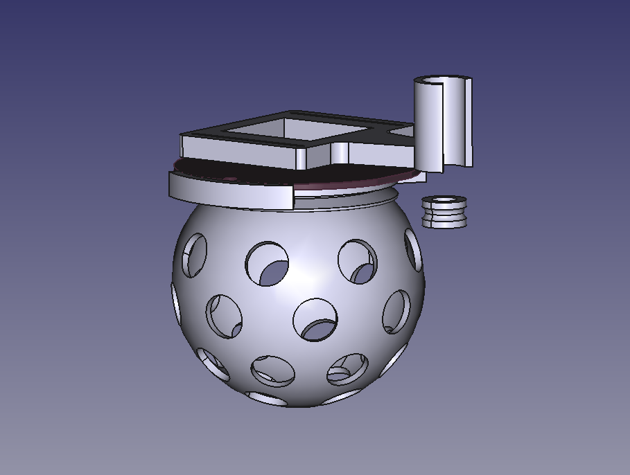
Coming from the software/electronic world, we have this notion of DRY: Do not Repeat Yourself. Ideally I would like to apply the same to mechanical design and avoid as much as possible to write any measurement by hand. one way to do that with FreeCAD is with Shape binder. A good example of its use is with the LED lens.
I wanted to put a translucent lens just on top of the Crazyradio LED. One way to achieve that is to create a Shape binder of the LED top surface onto the TOP and Lens. The LED top is the yellow square in the next picture and its presence allows to align perfectly the hole in the top cover to the middle of the LED on the PCB. This prevent all hazardous manual measurement when placing the hole.
For the lens design I can go one step further, I can create a shape binder both for the LED and for the hole in the top layer, this way the shape of the lens is derived from existing geometry and, to a large extent, does not have to be specified manually:
This allows to quite easily align the lens perfectly on top of the LED. The same principle is used for the button to get it to slide and press on the PCB switch with minimal play.
Final product
I pushed the current state of the case on GitHub. It is also available on Maker World. I plan on improving the design before deciding to name it 1.0 and to eventually upload it on Printables and Thingiverse.
If you want to learn more about FreeCAD, I can recommend this great video series on YouTube, it goes through a lot of very useful functionalities like the shape binders.
The ability to attach expansion decks to the Crazyflie platforms without modifying their electronics allows experimenting with different hardware components. Most existing decks contain different types of sensors that are used for positioning and collecting data. On this Fun Friday project that has been running for the past couple of months, I explored adding mechanical principles to the Crazyflie with the long-term goal to create a working claw to grab and transfer objects.
The claw
The claw mechanism is built on a DC motor. The motor shaft is connected to a worm gear, which drives the claw to open or close depending on the direction of rotation. All the parts are 3D printed and designed from scratch.
The deck
Making the DC motor rotate in both directions requires reversing its polarity, which can be done using an H-bridge. So, the deck controlling the claw, is essentially an H-bridge that uses VCC 3V, GND and 4 GPIO pins on the Crazyflie. This way it can be compatible with the Lighthouse positioning deck. The circuit consists of 4 Mosfets (2 P-type and 2 N-type) and 2 pull-down resistors.
How it works
When designing a custom deck for the Crazyflie, you need to initialize it with its own drivers. The drivers for the H-bridge deck contain 2 basic functions; the one that opens the claw and the one that closes it. They are triggered using 2 float parameters (clawOpen and clawClose), and remain active for the number of milliseconds specified by the value of each parameter.
Experiments
Since the entire claw setup weighs 29g, I used 2 Crazyflie 2.1 Brushless drones, to equally share the weight, while one of them controls the claw. Together, they can lift up to 74g. A fishing line is attached underneath each drone and the claw can slide along it, keeping it always centered between them. For the load, I used a Crazyflie 2.1+ with a lighthouse deck attached and its motors removed, to reduce its weight. When the script starts, the initial positions are collected and a flight sequence for the swarm is created based on them. Then, the swarm takes off and approaches, grabs, lifts and transfers the load.
Next steps
The initial goal of grasping and transferring objects with a flying claw has been achieved. However, in the future I plan to make the system more robust and easy to use. Some points that I might focus on:
Making the whole setup lighter – replace the current motor with a lighter one, print with lighter materials.
Improve the controller tuning to damp the oscillations and make the flight more stable.
Implement a control system to keep track of the claw’s state – add limit switches.
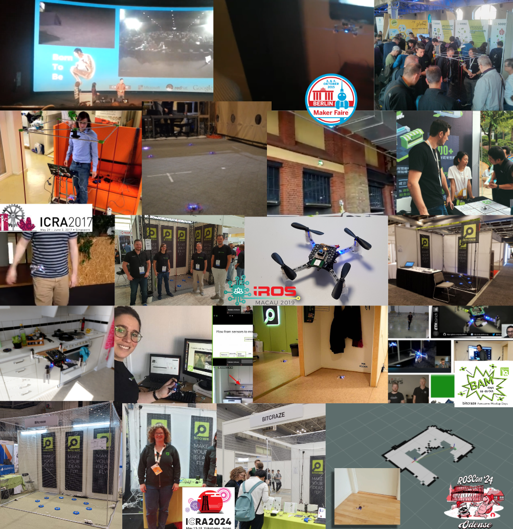
There is one thing that has driven both the hardware/software and our enthusiasm forward in the last 13 years, and that is making demos! Whether it’s a new piece of hardware/deck for the Crazyflie or the integration with an existing software framework, it doesn’t matter, but we have got to show it and, by all means… it needs to fly!
We have used fairs, conferences, and online meetings as perfect opportunities to push the capabilities of the little Crazyflie to the fullest. Of all the development goals we set, those self-made deadlines and over-ambitiousness have pushed both the hardware and software to the limit. In this blog post, we will take a look back at all of those demos we’ve done in the past and what we have learned from them.
2013 – 2017: Hacker and Developer Fairs
One of the very first conferences we were invited to was Devoxx in the UK. This was back in 2013, and we flew the Crazyflie (1) with an FPV camera over the actual crowd (blogpost, video), which was something we had already been working on for about half a year before showing it at the conference (blogpost, video). A year later, at Devoxx France (2014), they let us fly at the actual exhibition and over the booths, which showed much better quality (blogpost, video)! Not sure if they would still let us do this at fairs, but back then it was a bit of a wild west :D.
By the time the Crazyflie 2.0 was released, we started going to Makerfaires and even visited 3 of them, all in 2015! At the Makerfaire in the Bay Area (blogpost), New York, and Berlin (blogpost 1, blogpost 2), we prepared an external positioning system with the Kinect 2 and augmented reality markers (ArUco) (blogpost). That was one hectic year, and not without issues with the demo itself along the way (blogpost), but it showcased the Crazyflie and pushed the Crazyflie Python library and client to a more mature state.
Once 2016 came, the ultra-wideband positioning hacks reached a point where we could start demoing them as well. At first, the positioning was still calculated offboard with a ROS(1) node and transmitted to the Crazyflie, which was first showcased at Makerfaire Berlin 2016 (blogpost, video) at the booth itself. Eventually, a live demo was given at FOSDEM 2017 in the actual devroom for Embedded, Mobile, and Automotive (talk page). The Flowdeck was also in development at that time, and we had a small tabletop demo at Makerfaire Shenzhen 2017, where people could press a button, and the Crazyflie would take off, fly a circle, and land again (blogpost, video).
2017 – 2019: Academic Robotics Conferences
From 2017, we made it a habit to also meet with our research users, so we started going to academic robotics conferences as well, starting with ICRA 2017 in Singapore. Here, we showcased the Loco Positioning System, where the positioning was estimated onboard, so no external computer was required to perform the calculations (blogpost, video).
At IROS 2018, we took it up a notch by joining our collaborator Qualisys, showcasing the Loco Positioning System for a swarm, Motion Capture-based localization, and the brand new Lighthouse positioning prototype (blogpost 1, blogpost 2). We also added autonomous charging to it as well, so it was a great deal of work! Maybe we took on a bit too much, but one thing is for sure—we learned a lot by doing it (blogpost 1, blogpost 2, video)! With ICRA and IROS 2019, we perfected the circling swarm demo so that it was fully autonomous. However, this time we only used the Lighthouse positioning system since it was a bit easier to set up (blogpost 1, blogpost 2, video). The computer still had to command which Crazyflie to start flying, but other than that, we didn’t have to mind it that much and had plenty of time to talk with the users.
2020 – 2022: Covid and the Home Lab
As everyone knows—and probably tries to forget—2020 was the year that Covid hit us hard, and we couldn’t travel anywhere anymore. For us, it was quite an adjustment period, as we had to find another type of motivation to keep moving forward and continue development. We introduced the concept of the home lab and gave online talks and tutorials to still show cool stuff with the Crazyflie to the world (blogpost, video).
In 2020, we all joined together to work on the Hyper demo, which was a showcase that demonstrated the Crazyflie could fly with three positioning systems at the same time, enabling it to fly all the way from the meeting room to the flight arena (blogpost, video). We also celebrated Bitcraze’s 10-year anniversary with the BAM Days, a full 3-day online seminar about all things Crazyflie, for which we and our collaborators prepared a whole range of different demos, including a Rust-based app layer example and a peer-to-peer onboard swarming example (blogpost).
2022-now: Back to conferences
At the end of 2022, we managed to go to fairs again, namely IMAV and IROS 2022, where we showcased the fully autonomous swarm demo as before Covid hit. However, due to the demos we conducted during Covid, we also added full onboard peer-to-peer communication. This enabled the Crazyflies to negotiate which Crazyflie could take off, which pretty much completely eliminated the need for an external computer. Moreover, the Crazyflies communicated their positions to each other, which made it possible for them to avoid collisions on the fly (blogpost, video).
We have shown this demo as well for ICRA 2023 in London (blogpost) and ICRA 2024 in Yokohama (blogpost) with different variations and the upcoming brushless version as well (blogpost). The demo is quite robust, but it’s great to learn about the quality of the new motors and props, the guard prototypes of the Crazyflie Brushless, and the flight stability. But as you know us by now, it is time for something different!
Soon – ROSCon 2024
We have been to ROSCon before, back in 2022 (blogpost), but now we will be going to ROSCon 2024 for the first time as exhibitors (blogpost). ROS is a framework that is used by many researchers, including our users through Crazyswarm2, but ROSCon is more developer-oriented, and there will be more companies present that focus more on industry than academia. This time we won’t show our swarm demo as we usually do, but we will be showing demos more in line with what is presented in the ROS skill learning session of the robotics developer day (blogpost, video), but we will be hacking around on the spot! So this will be something new for us to try out, and we are very much looking forward to it!
Developer meeting, 9th of October 2024
This blog post only represents a subset of demos that we have done, but we will go into further detail at the next developer meeting on Wednesday, the 9th of October, at 3 PM CEST! Please join us to learn about all the great demos we have done in the past, get a glimpse of the history of Bitcraze, and discuss why demo-driven development is so important in moving your development forward.
As you might expect, we use the Crazyflie python client a lot at Bitcraze. The client has a lot of features, ranging from setting up LPS/Lighthouse systems to turning on/off the headlight LEDs on the LED-ring deck. But some of the features we use the most is probably the console view as well as the logging/parameter subsystems. A lot of the time we modify firmware, flash it and want to tweak (via parameters) or to check if the changes are working as expected (via the console or logging). Then switching from the terminal, where we build/flash, to the Qt UI in the Crazyflie python client can be a hassle if you just want to do something quick. It would be great to be able to log/set variables directly from the terminal, well now you can!
Meet the Crazyflie command-line client, a fun Friday project I worked on a while back. The CLI is written in Rust and was made possible thanks to a previous fun Friday project by Arnaud on the Rust Crazyflie link/lib, which has now moved to the official Bitcraze repositories. The CLI project is still very limited, but has some basic functionality:
Scan for Crazyflies and pre-select one to interact with
List loggable variables, create log configurations and print their value
List parameters and get/set them
Show the Crazyflie console
Last week the first version, v0.1.0, was released on crates.io. So if you have Rust set up on your computer and want to test it out then all you need to do is to type “cargo install cfcli“. The CLI still only has some basic functionality, but hopefully it can be expanded in the future with more useful things! Feel free to leave any issues or comments you might have on the Github page.