At Bitcraze we really have a front-row seat in robotics research. Every week, various papers appear: Conference papers, PhD theses, journal articles, and preprints that resonate across the community. Sometimes they arrive from universities we’ve worked with for years, and sometimes from labs we’ve never heard of before.
We are constantly humbled by the possibilities and the lengths that the community takes the platform. Although applications seem endless, we’ve grouped recent papers from the community into broad categories to give a useful snapshot of how different labs and research groups are answering questions from different angles.
Swarms are all about robustness (and size)
A decade ago, entire keynote talks revolved around ever-larger choreographed formations. Don’t get me wrong, it’s always impressive to see large swarms, but recent papers seem to increasingly raise questions around reliability.
How do individual robots coordinate without overwhelming the communication network? What happens when information arrives late? What if one vehicle fails? How do you distribute decisions without relying on a central controller?
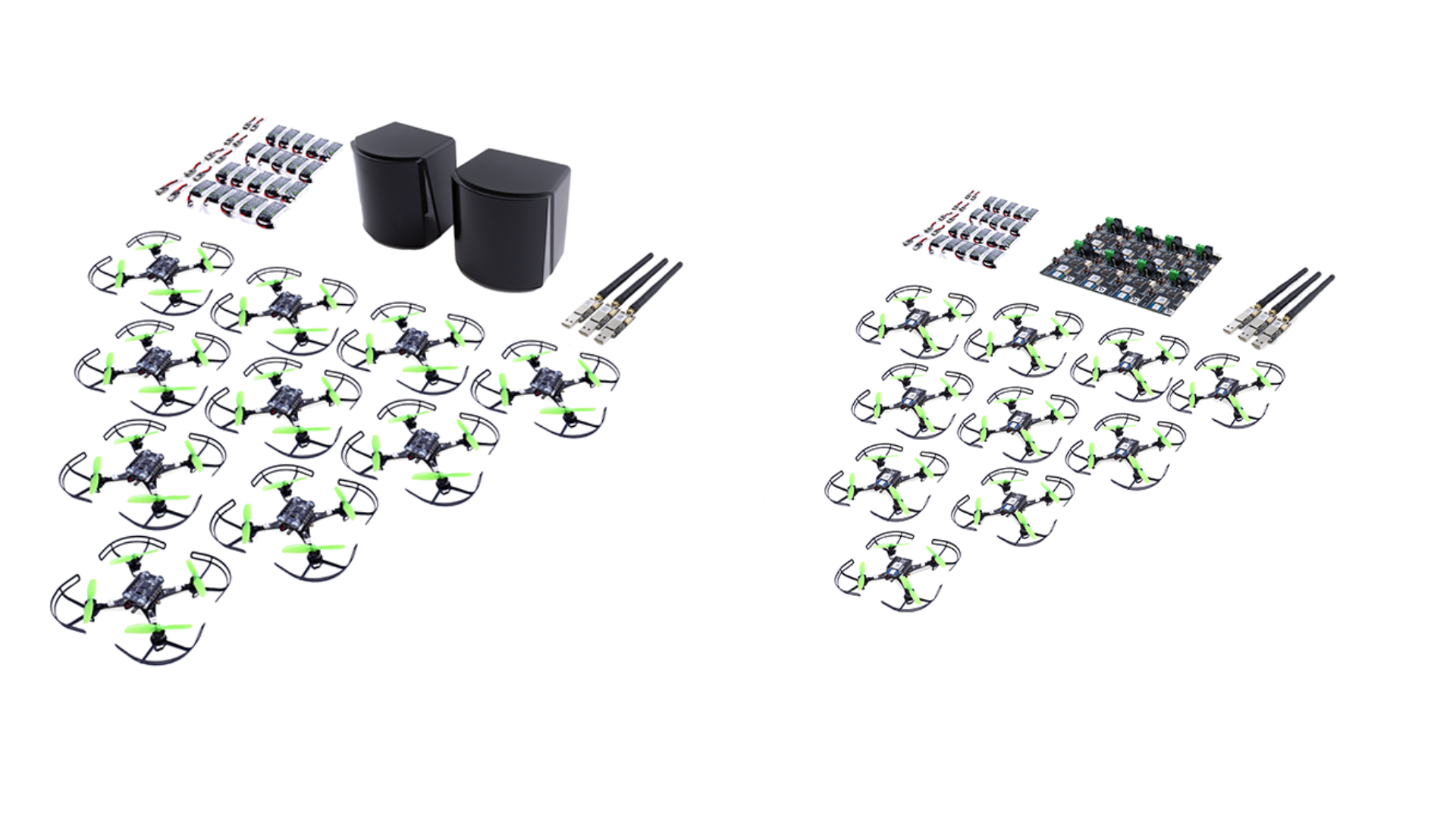
DMPC-Swarm: Distributed Model Predictive Control for Nano-UAV Swarms is a good example. Rather than treating coordination as a centralized optimisation problem, the authors investigate distributed model predictive control, with the optimization shared across the swarm rather than handled by a single central unit (see https://link.springer.com/article/10.1007/s10514-025-10211-w).
It’s also interesting to see how much current work still builds on the foundations laid by the original Crazyswarm framework (https://ieeexplore.ieee.org/document/7989376). Nearly a decade later, it continues to serve as a reference point for new ideas, while more recent work pushes towards larger, more resilient, and more scalable swarm systems (https://ieeexplore.ieee.org/document/10611499).
Flying robots are literally touching the world
The most common drone use case is still the observer. To inspect bridges, map forests, measure crops, and capture data, but aerial manipulation turns that idea upside down.
Instead of asking what a flying robot can see, researchers ask what it can do. Some groups investigate cooperative payload transport (https://ieeexplore.ieee.org/document/8461014). Others focus on cable manipulation and contact-rich interaction (https://ieeexplore.ieee.org/document/10382688). More recent work explores increasingly sophisticated manipulation strategies while maintaining stable flight (https://ieeexplore.ieee.org/document/10802794).
Aerial manipulation forces multiple disciplines together. Control theory, estimation, mechanical design, and physical interaction all become tightly coupled. As these systems mature, flying robots may increasingly move beyond sensing and inspection roles into applications that require direct interaction with the physical world.
The challenge of making AI practical
Look anywhere and everything’s “AI”, but thankfully the research papers tell a nuanced story. Researchers are asking practical questions, if learning can improve flight performance without sacrificing stability, if sophisticated controllers can run on tiny embedded processors, and if simulation can reduce the amount of expensive real-world data needed before deployment?
DATT: Deep Adaptive Trajectory Tracking explores how learned components can complement classical control methods under uncertain conditions (https://arxiv.org/abs/2310.09053).
Learning to Fly in Seconds takes another route, demonstrating how efficient training in simulation can dramatically shorten the path to successful real-world flight (https://ieeexplore.ieee.org/document/10517383).
Palossi et Al. investigates yet another line of research on how machine learning can be integrated directly into flight control, allowing nano-quadcopters to improve their performance while remaining reliable and computationally efficient (https://ieeexplore.ieee.org/document/8715489)..
The frontier isn’t simply making robots smarter. It’s making sophisticated autonomy accessible on hardware small enough to fit in the palm of your hand.
Can robots learn to work with people, not just around them?
Technical performance alone doesn’t determine whether a robotic system is successful. People need to understand what the robot is doing, communicate with it naturally, and develop enough confidence to work alongside it.
That has led researchers to investigate everything from gesture-based interfaces, or “SwarmTouch” (https://ieeexplore.ieee.org/document/8758191) to shared autonomy in Hand-worn Haptic Interface for Drone Teleoperation (https://ieeexplore.ieee.org/document/9196664) and broader questions around interaction and collaboration between humans and aerial robots bu La Delfa et Al. (https://ieeexplore.ieee.org/document/10973956).
In some cases, the hardest challenge is not controlling the robot itself, but designing the relationship between humans and machines. After all, even the most capable autonomous system ultimately exists to help someone accomplish something.
Sometimes the cleverest solution is the simplest one
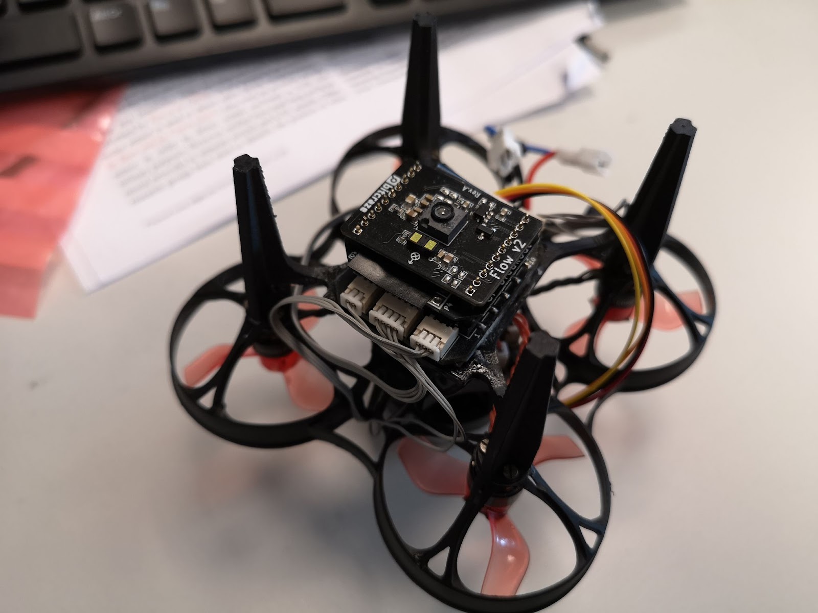
Before a robot can make intelligent decisions, it must know where it is. For small aerial robots, this question is particularly challenging, since limited payload capacity restricts sensor choices, while limited onboard compute constrains what algorithms can realistically run. This has made nano-quadcopters an attractive platform for investigating efficient perception and navigation techniques.
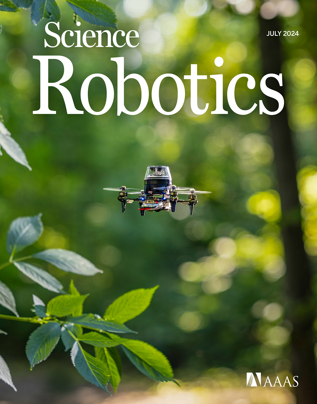
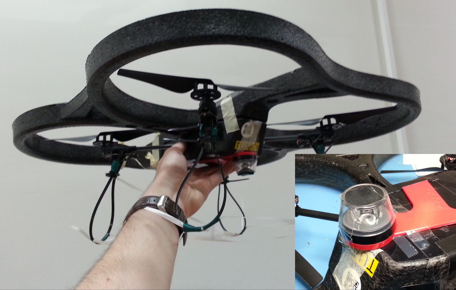
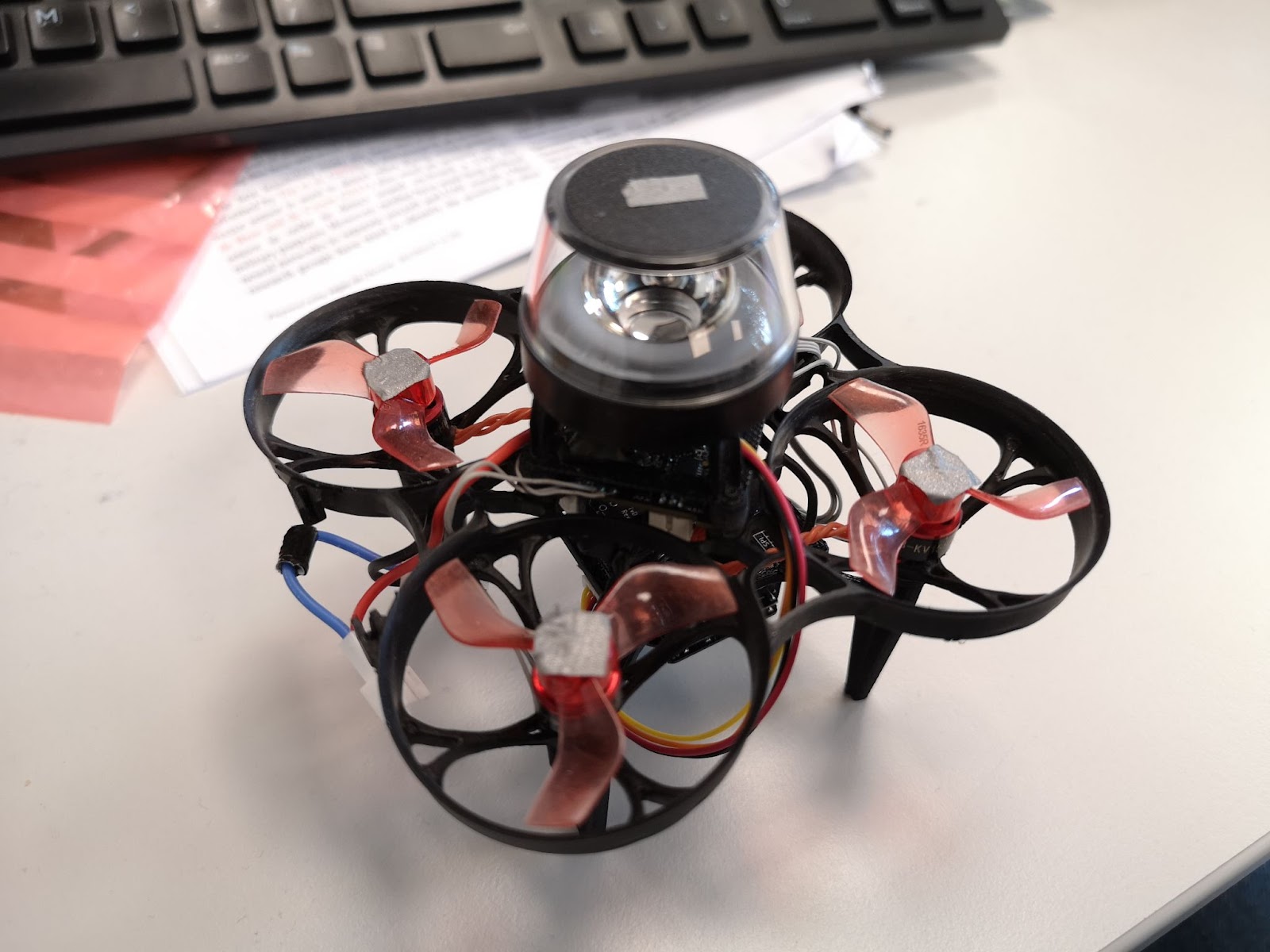
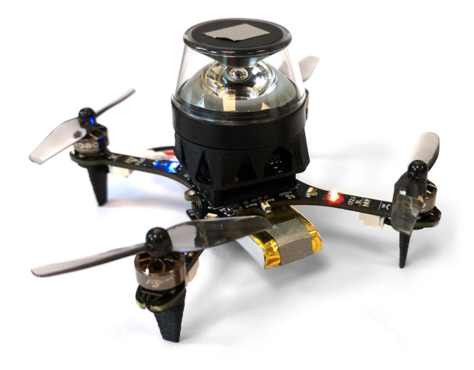
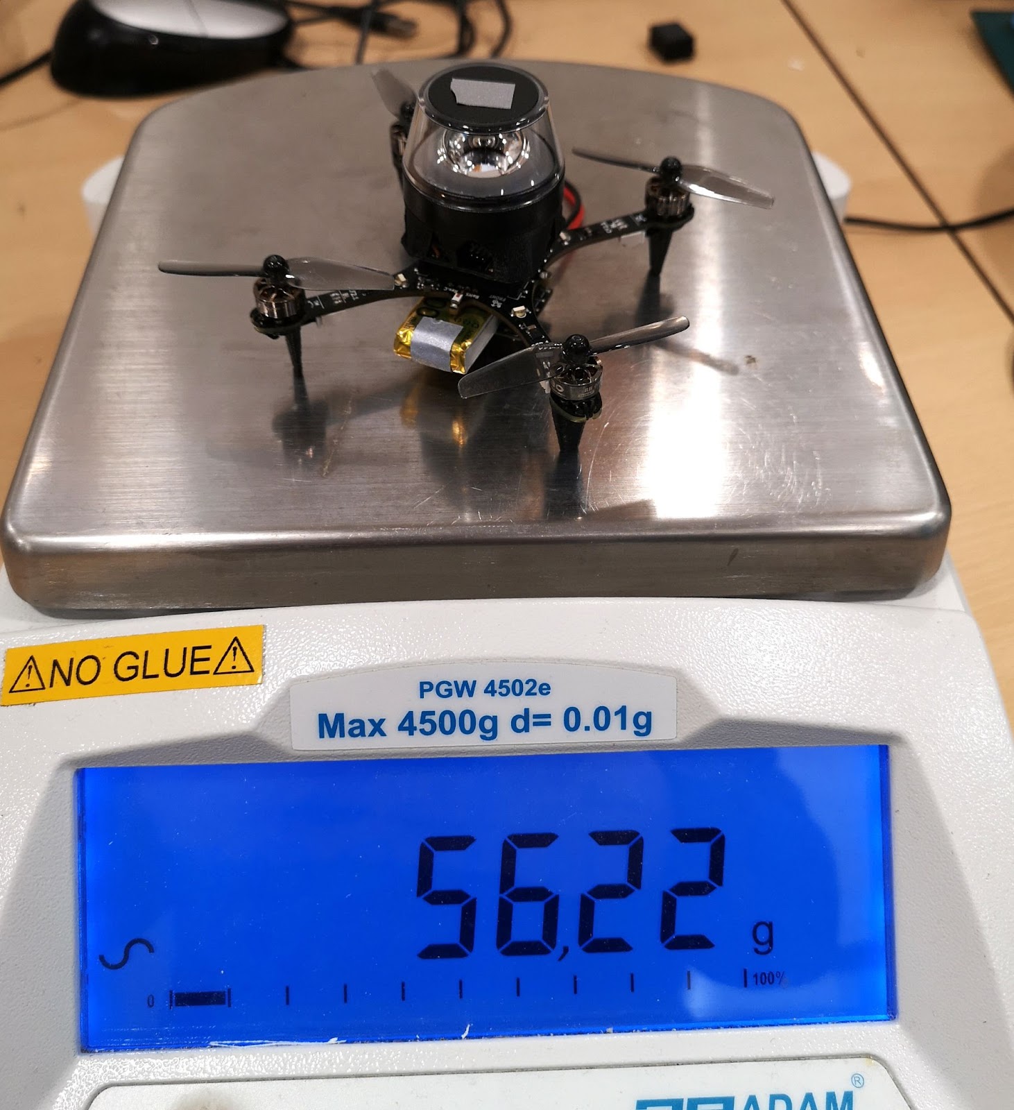
In Visual Route-following for Tiny Autonomous Robots, published in Science Robotics, researchers demonstrated an insect-inspired navigation strategy using an omnidirectional camera mounted on a Crazyflie Brushless (https://www.science.org/doi/10.1126/scirobotics.adk0310).
Rather than constructing detailed maps of the environment, the robot simply learns visual routes and follows them. It’s an elegant reminder that engineering progress doesn’t always come from adding complexity, but from asking what can be removed.
That same philosophy appears elsewhere in recent perception and navigation research, where teams continue to develop increasingly efficient onboard perception and localization methods suited to the severe constraints of nano-quadcopters. NanoSLAM: Enabling Fully Onboard SLAM for Tiny Robots (https://ieeexplore.ieee.org/document/10343110, and Robust and Efficient Depth-Based Obstacle Avoidance for Autonomous Miniaturized UAVs are perfect examples of this (https://ieeexplore.ieee.org/document/10272390).
A community exploring difficult problems
What makes the broad body of Crazyflie research interesting is the sheer variety of approaches researchers bring to the same fundamental challenges. Across universities, laboratories, and disciplines, researchers continue to investigate cooperation, physical interaction, learning, perception, and human collaboration from different angles.
Taken together, these projects provide a glimpse of where robotics research is heading. There’s clearly more to find out, and we’re glad to keep being part of how people go looking.
Visit our Applications pages for more examples of how researchers, educators, and innovators are using the Crazyflie.