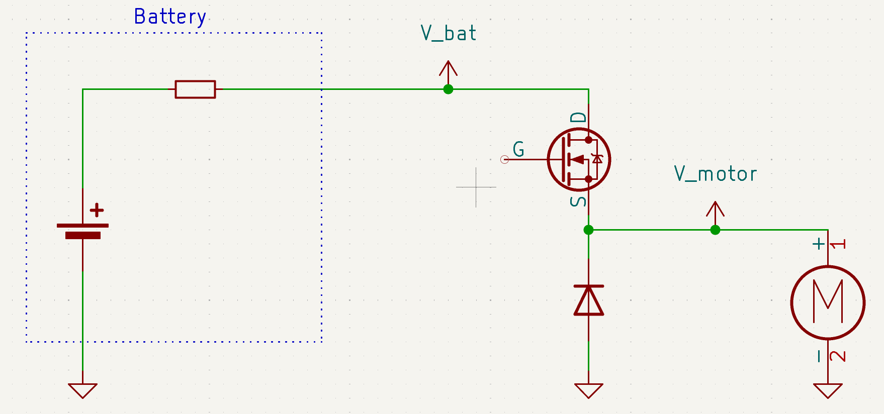
The Crazyflie 2.1 Brushless uses the DSHOT protocol to command its ESCs — a clean, digital, CRC-protected signal that replaced the old analog PWM signals. But until now, that communication was strictly one-way: the firmware sends a throttle command and hopes for the best. There’s no direct feedback from the motors about what they’re actually doing, even if the brushless motors are naturally able to do that by sensing the back-EMF on their windings.
This matters more than it might seem. The relationship between a commanded throttle value and the actual motor RPM is nonlinear and varies with battery voltage, temperature, and load. For anything beyond basic hovering — system identification, simulation validation, advanced controllers — you want to know the actual motor speed, not just what you asked for. Previously, measuring RPM required external instrumentation, such as an optical tachometer or a thrust stand. Useful on the bench, but impractical in flight.
As part of our recent work at IDSIA on nonlinear system identification for the Crazyflie 2.1 Brushless, we developed a new bidirectional DSHOT driver to change this. Each ESC now reports its electrical RPM back over the same signal line used for commands, giving us per-motor RPM telemetry at every control cycle. The new driver was just merged in the firmware and it’s now available for everyone to use (PR #1556).
What is Bidirectional DSHOT?
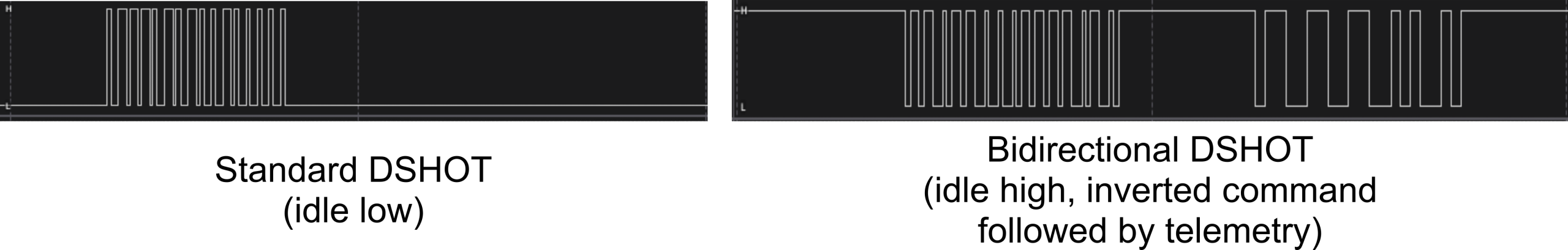
Standard DSHOT encodes a throttle command as a sequence of bit periods on a digital line: each bit is either a short or a long pulse, with the full frame containing an 11-bit throttle value, a telemetry request flag, and a 4-bit CRC. It’s fast, noise-resistant, and needs no calibration. In other words, a major step up from the analog PWM for the old Crazyflie 2.1 Brushed.
Bidirectional DSHOT extends this with a simple trick. After the flight controller finishes transmitting a command frame, it releases the line (sets the GPIO to input). The ESC responds with a telemetry packet containing its current electrical RPM (eRPM), encoded using a GCR (Group Code Recording) scheme. The whole exchange, i.e., command out, telemetry back, takes roughly 150 µs. To enable bidirectional mode, the STM32 inverts the polarity of the DSHOT line (idle-high instead of idle-low), which the ESC recognises as a request to reply with telemetry.
The eRPM value from the ESC reports electrical rotations. To get the mechanical RPM that actually matters, you divide by half the number of motor poles: RPM = eRPM / (poles / 2). For the motors on the Crazyflie Brushless, this is 12 poles per motor, but the driver can be customized with a fixed constant set at build time.
This protocol is well-established in the FPV and Betaflight ecosystem, where it’s used for RPM filtering in flight controllers. The ESC firmware on the Crazyflie Brushless (BlueJay) already supports it. The missing piece and technical challenge was the firmware on the STM32 side.
Implementation
Bidirectional DSHOT turns a transmit-only interface into a half-duplex one: the same physical line must alternate between output (command) and input (telemetry). On the Crazyflie’s STM32, implementing this must account for a few hardware constraints.
DMA Input Capture for receiving telemetry
Rather than polling or bit-banging the telemetry response, the firmware uses DMA Input Capture: it configures the timer to record a timestamp at every edge transition on the DSHOT line, with DMA transferring each timestamp to a buffer without CPU intervention. After the command frame is sent, the code opens a 100 µs receive window (accounting for 30 µs of wait time, around 50 µs for the telemetry packet, plus some headroom). Once the window closes, the buffer contains a sequence of edge timestamps that can be decoded into the GCR telemetry frame at leisure.
This is the same approach used in Betaflight’s bidirectional DSHOT implementation, adapted to the Crazyflie’s timer and DMA configuration.
Hardware conflicts
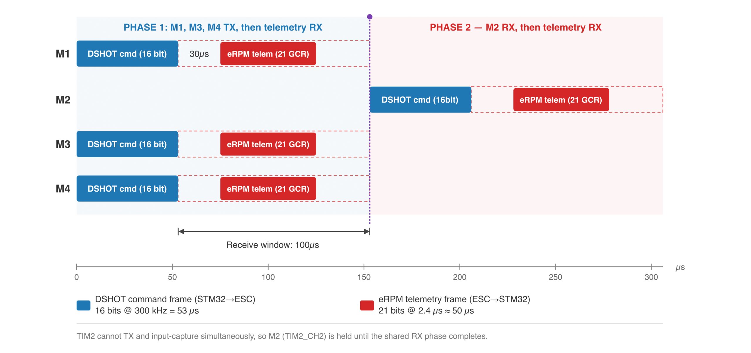
All four motor DSHOT outputs share the TIM2 timer on the STM32. This was not an issue with traditional DSHOT: the timer is left free-running, and each motor can be controlled independently. With bidirectional DSHOT, the transmit and receive phases require different timer periods (the command and telemetry frames have different bit rates), so the transmit and receive phases can’t overlap between motors.
The solution is a two-phase scheme within each control cycle:
- Phase 1: Transmit command frames to motors M1, M3, and M4. After transmission, switch the lines to input and capture their telemetry replies.
- Phase 2: Once the receive window closes (detected by a TIM2 interrupt), transmit the command to M2 and capture its reply.
This sequencing means M2’s command is delayed by roughly 100 µs relative to the other motors — the cost of sharing a single timer. In practice, at the Crazyflie’s control rate, this additional latency is negligible.
What you get
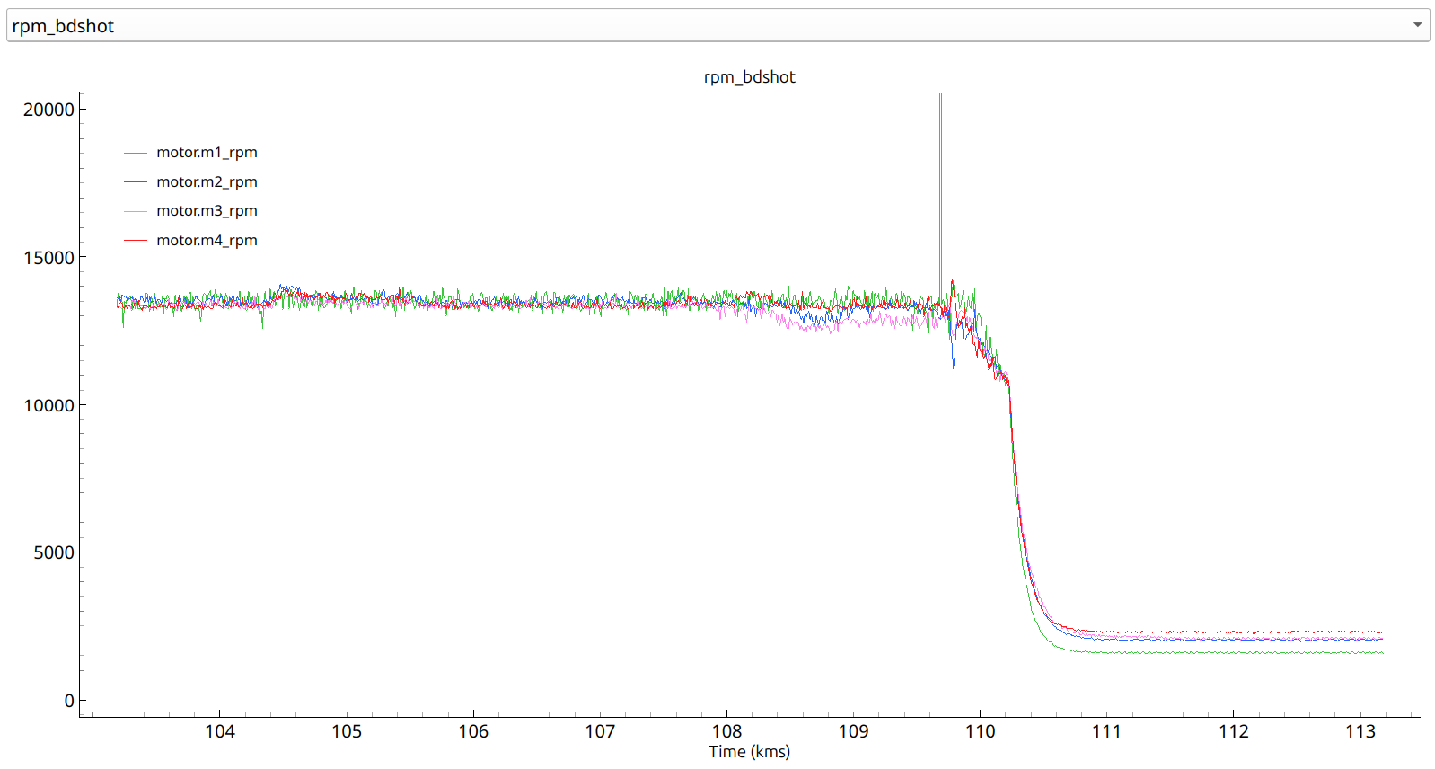
With bidirectional DSHOT enabled, the firmware exposes four new log variables:
motor.m1_rpmmotor.m2_rpmmotor.m3_rpmmotor.m4_rpm
These can be streamed and recorded through cfclient like any other log variable, at the full control loop rate.
Validation
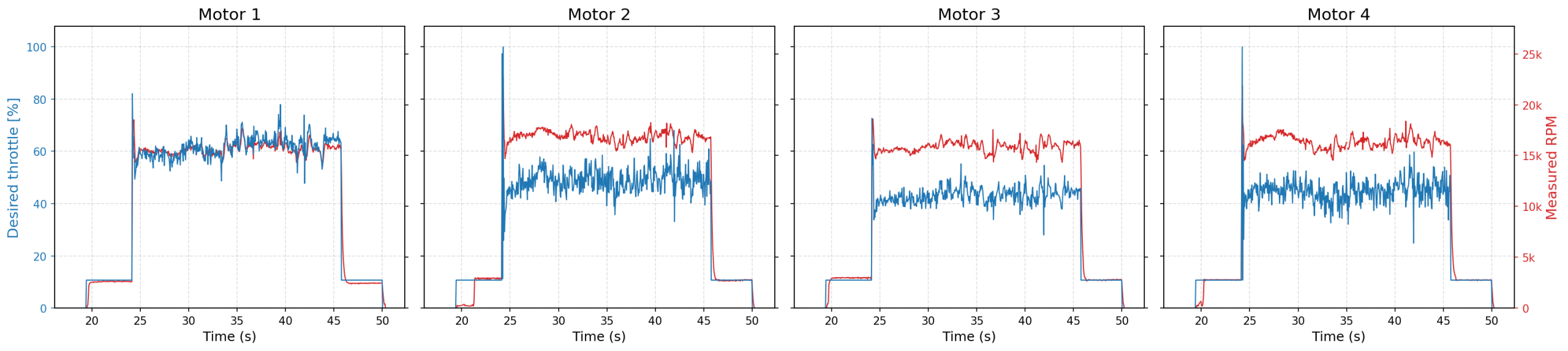
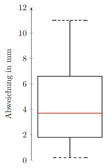
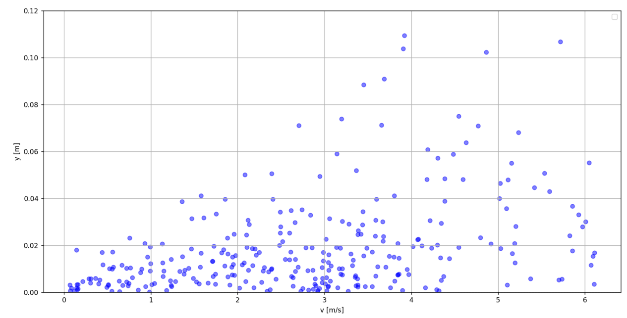
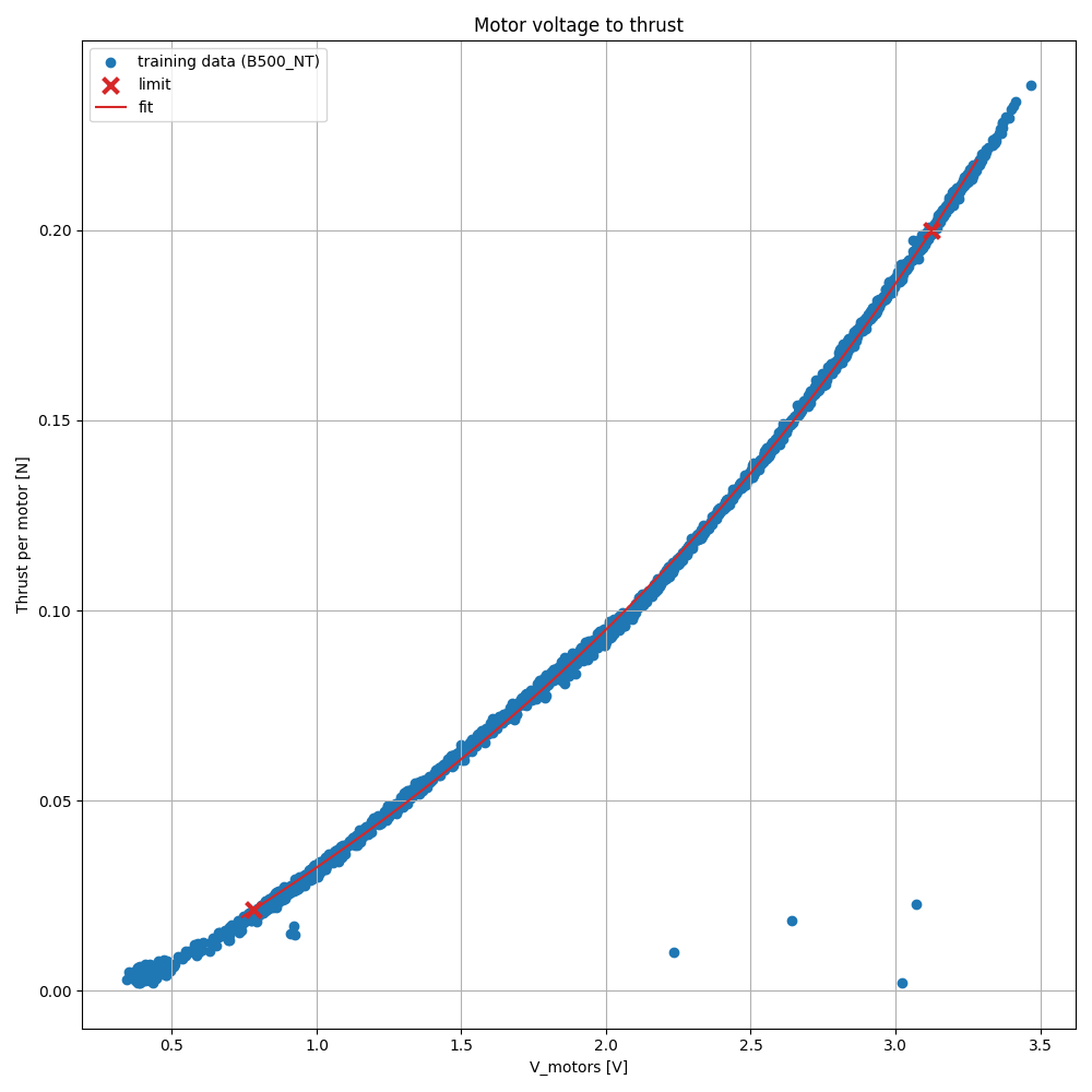
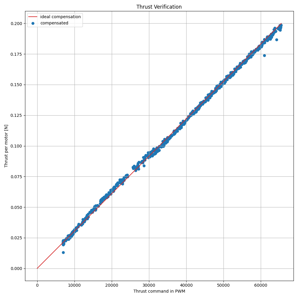
To verify that the telemetry readings are correct, we compared the reported RPM values against the thrust-stand characterisation performed for the battery compensation work. At a given commanded thrust and battery voltage, the expected RPM can be computed from the motor voltage–thrust polynomial and the motor’s known Kv constant. The onboard RPM readings match this prediction well across the operating range.
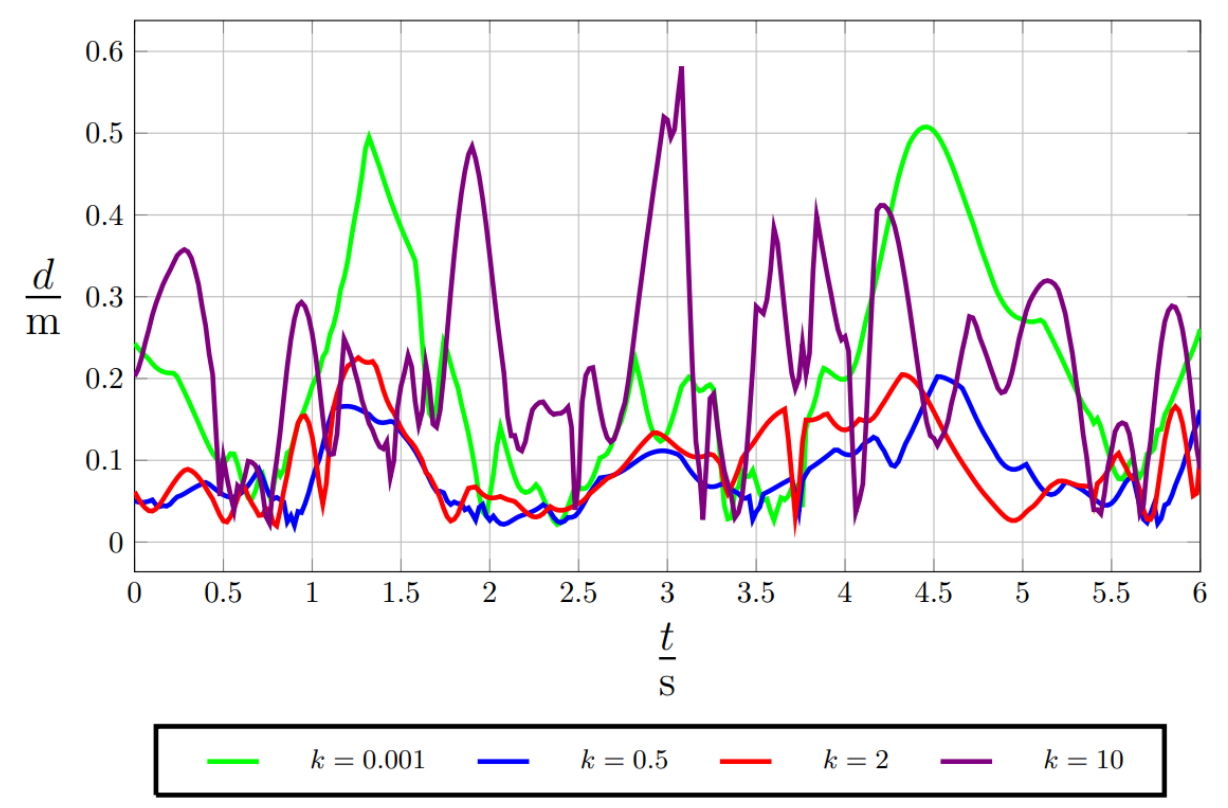
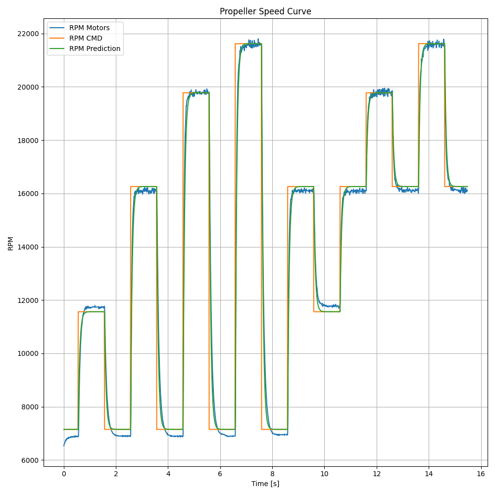
During flight, the RPM traces clearly show the motor dynamics that the open-loop command model doesn’t capture: spin-up and spin-down transients, asymmetries between motors, and the RPM dips that correspond to aggressive attitude changes. This is exactly the kind of information that was previously invisible to the firmware.
Applications
Per-motor RPM telemetry opens the door to several applications.
System identification with measured actuator signals
RPM telemetry changes what’s possible for system identification. In previous nano-drone datasets, the “motor input” is the commanded PWM or throttle value — but the actual motor response differs from the command due to ESC dynamics, battery sag, and nonlinear torque curves. Any model trained on commanded inputs cannot disentangle these actuation nonlinearities from the airframe dynamics it’s actually trying to capture.
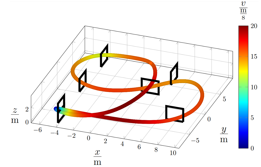
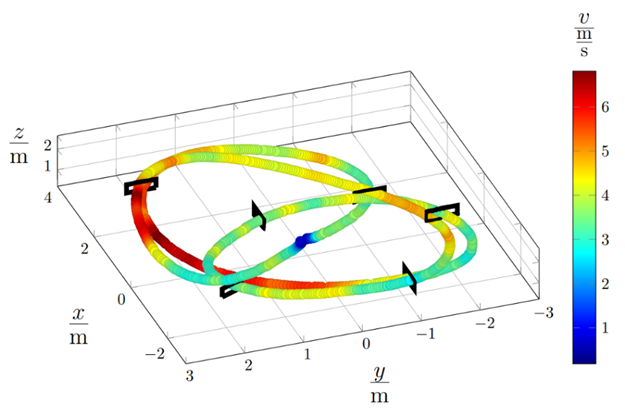
This is exactly the problem we addressed in Busetto et al. (2025): we released a benchmark for nonlinear system identification based on the Crazyflie 2.1 Brushless. The dataset contains 75k real-world samples across four aggressive flight trajectories, with synchronised 4-dimensional motor RPM inputs and 13-dimensional output measurements (IMU + motion capture). Crucially, the motor inputs are measured RPMs from bidirectional DSHOT — not commanded values. This cleanly separates the actuation subsystem from the airframe dynamics, giving identification algorithms a much better signal to work with.
The benchmark includes multi-horizon prediction metrics for evaluating both one-step and multi-step error propagation, along with baseline models ranging from physics-based to neural network approaches. All data, scripts, and reference implementations are open-source at github.com/idsia-robotics/nanodrone-sysid-benchmark. The firmware feature described in this post directly enabled this data collection.
Closed-loop RPM control
Beyond identification, using RPM telemetry as closed-loop feedback enables new opportunities in control. The battery compensation scheme introduced in PR #1526 solves the voltage-sag problem by adjusting the PWM command based on measured battery voltage and a motor voltage–thrust polynomial. It works well, but it’s fundamentally still open-loop with respect to the motor itself: the firmware corrects for the expected effect of voltage on thrust, without ever checking whether the motor actually reached the intended speed.
With RPM feedback, a different approach becomes possible: close the loop at the motor level. Instead of commanding a PWM duty cycle and compensating for voltage, command a target RPM and let a per-motor controller (or the ESC’s own closed-loop mode) handle the rest. This makes the thrust response inherently invariant to battery voltage, temperature drift, and propeller wear — anything that shifts the relationship between PWM and actual speed.
Broader impact
Having RPM as a standard logged variable on an open-source, commercially available nano-drone lowers the barrier for the entire research community. Anyone with a Crazyflie Brushless can now collect flight dynamics datasets with true actuator measurements, validate sim-to-real transfer (e.g., with Crazyflow), or prototype RPM-aware controllers — without any hardware modifications.
Try It
Bidirectional DSHOT is available today and enabled by default in the main branch of the Crazyflie firmware. To use it:
- You need a Crazyflie 2.1 Brushless with BlueJay ESCs (the stock configuration).
- Log the
motor.m{1,2,3,4}_rpmvariables through cfclient.
It is also used by the supervisor to check that all motors has spun up during arming or if a motor is blocked during flight. We’re looking forward to community feedback. Let us know how it works for you.