We have had numerous request to get a transfer function from the motor PWM output to propeller RPM. The next step would then be to get the propeller RPM to thrust transfer function as well. With that it is easier to do calculations on the system and mathematical models. So this and probably next post will be about how to obtain this function and also give a bit of insight in how one can do development with the Crazyflie 2.0.
First thing how do one do propeller RPM measurement? A quick search on the internet and you will find that using an optical switch is a common method. I also found this guide written for Arduino which was a great start. Since I preferable wanted to measure the RPM while flying the switch needed to be small and lightweight. I found two types that could be useful. A slotted type and a reflective type. The reflective type, QRD1114, is small and promising but would it work? I got some of each type just in case.


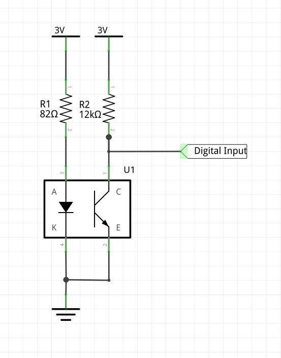
Now the optical switch needs interfacing and power. Sparkfun made a good tutorial using the QRD1114 sensor so I will not go into details. Since we use 3V instead I adjusted the resistor for the LED to 82 ohms instead. This will give me ~20mA emitter current. I also played a bit with the sensor output pull-up resistor. If you go with a to strong pull-up, the sensor will need a lot of light to pull it down and if it is to week, it will rise to slow. 12k pull-up seams like a good compromise in my lighting conditions.
As a first thing I wired it up on a breadboard using the Crazyflie 2.0 breakout board to get a sense if it would work or not. My finding by measuring the output signal with a multimeter is that it is pretty sensitive to surrounding light but that could be solved by flying in a dim room since it is mainly intended to be used for research.


Now it was time to build a circuit using the prototyping expansion board. I also multiplied the circuit 4 times so I can measure all 4 motors. The inputs I use was TX2, RX2, IO2 and IO3. This because they are all connected to timers so I could use the input capture timer functionality later when I get to the software part. Bending the legs on the QRD1114 was a pretty fiddly job but worth it as it came out so cool in the end. Before I connected it to the Crazyflie 2.0 I measured the current draw and it all seamed OK, ~80mA (4 x 20mA). I also double checked all the connections since it is easy to put a lot of time thinking it is a software fault later if things aren’t working as they should.


As a first test I just turned on one of the motors at a PWM of 10000 and measuerd the sensor output with a scope. The black color of the propeller wasn’t so good so I searched around in the office and found some reflective paint we used a while ago. I painted the backside of the propeller and it made a big difference. In the pictures below you can find the scope picture using a 12k pull-up and some pictures of the painted props.


Next part I will start doing the software and analysis so stay tuned!
Wow! This looks like a cool project. I’m very interested in seeing the next post. It’s cool to see how the breakout and prototype boards made it easy to experiment with, then integrate, the sensors.