This week we have a guest blog post from Percy Jaiswal about quad rotor dynamics. Enjoy!
- Components
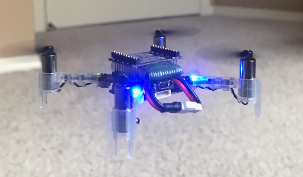
Although most of us are aware how a quadcopter / drone looks, a generic picture (It’s of a drone called Crazyflie from Bitcraze) of drone is shown above. It consists of 4 motors, control circuitry in middle and Propellers mounted on its rotors. For reasons described in below section, 2 of the rotors rotate in clockwise (CW) direction and remaining 2 in counterclockwise (CCW). CW and CCW motors are placed next to each other to negate Moment (described in next section) generated by them. Propellers come in different configurations like CW or CCW rotating, Pusher or Tractor, with different radius, pitch etcetera. -
Force and Moments
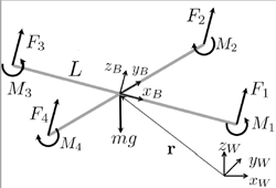
Each rotating propeller produces two kind of forces. When a rotor rotates, it’s propeller produces upward thrust given by F=K_f * ω² (shown by forces F1, F2, F3 and F4 in Figure 2) where ω (omega) is rotation rate of rotor measured in radian / second. Constant K_f depends upon many factors like torque proportionality constant, back-EMF, Density of surrounding air, area swept by propeller etc. The values for K_f and K_m (mentioned below) are generally found empirically. We mount the motor and propeller on a load cell and measure the force and moment for different motor speeds. Refer “System Identification of the Crazyflie 2.0 Nano Quadrocopter” by Julian Forster for details regarding measurement of K_f and K_m.
Total upward thrust generated by all 4 propellers is given by summing all individual thrusts generated, for i= 1 to 4 its given by
F_i = K_f * ω²
Apart from upward force, a rotating propeller also generates an opposing rotating spin called Torque or Moment (shown by Moments M1, M2, M3 and M4 in Figure 2). For e.g. a rotor spinning in CW direction will produce a torque which causes the body of drone to spin in CCW direction. A demonstration of this effect can be seen here. This rotating torque is given by M=K_m * ω²
Moment generated by a motor is in opposite direction to its spinning, hence CW and CCW spinning motors generate opposite moments. And this is the reason why we have CW and CCW rotating motors so that in steady hover state, moments from 2 CW and 2 CCW rotating rotors negate each other out and drone doesn’t keeping spinning about its body axis (also called yaw).
Moments / Torques M1, M2, M3 and M4 are moments generated by individual motors. The overall Moment generated around drone’s z axis (Z_b in Figure 2) is given by summation of all 4 moments. Remember that CW and CCW moments will have opposite signs.
moment_z = M1 + M2 + M3 + M4, again CW and CCW moments will have opposite signs and hence in ideal condition (or whenever we don’t want any Yaw (rotation around z axis) movement) moment_z will be close to 0.
Contrary to moment_z, overall moment / torque generated around x and y axis’s calculations are little different. Looking at Figure 2, we can see that motor 1 and 3 lie on x axis of drone. So they won’t contribute to any moment / torque around x axis. However we can see that difference in forces generated by motor 2 and 4 will cause drone’s body to tilt around it’s x axis and this is what constitutes overall moment / torque around x axis, which is given by
moment _x = (F2 — F4) * L, where L is the distance from the axis of rotation of the rotors to the center of the quadrotor. By same logic,
moment _y = (F3 — F1) * L.
Summing it up, moment around all 3 axis can be denoted by below vector
moment = [moment_x, moment_y, moment_z]^T (^T for Transpose) - Orientation and position
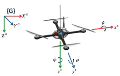
A drone has positional as well as orientational attributes, meaning to say it can be any position (x, y, z coordinates) and can be making certain angles (theta (θ), phi (φ) and psi (ψ)) with respect to world / Inertial frame. Above figure shows theta (θ), phi (φ) and psi (ψ) more clearly. - Moving in z and x & y direction
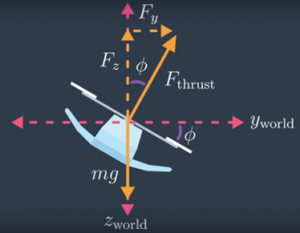
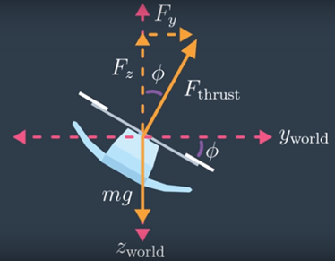
Whenever a drone is stationary, it’s in alignment with World frame, meaning to say its Z axis is in same direction as World’s gravitational field. During such a case, if a drone wants to move upwards, it just needs to set proper propeller rotating speed and it can start moving in z direction according to equation total generated force — gravity. However, if it wants to move in x or y direction it first needs to orient itself (making required theta or phi angle). When that happens, total thrust generated by four propellers (F_thrust) has a component in z direction and in x/y direction as shown in above 2D figure. For above shown example, using basic trigonometry, we can find z and y directional force by following equation, where phi is angle made Drone’s body z axis with world Frame.
F_y = F_thrust * sinϕ
F_z = F_thrust * cosϕ - World and Body frame
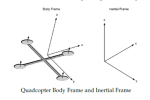
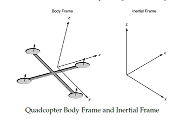
To measure above stated theta, phi and psi angles, usually drone’s onboard IMU sensor is used. This sensor measures how fast drone’s body is rotating around its body frame and provides that angular velocity as its output. When processing this IMU outputs, we need to be careful and understand that angular velocities sent by it are not with respect to World frame, but are with respect to its Body Frame. Above diagram shown both this frames for reference. - Rotation Matrix
To convert coordinates from Body Frame to World Frame and vice versa, we use a 3×3 matrix called Rotation Matrix. That is, if V is a vector in the world coordinates and V’ is the same vector expressed in the body-fixed coordinates, then the following relations hold:
V’ = R * V and
V = R^T * V’ where R is Rotation Matrix and R^T is its transpose.
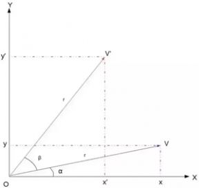
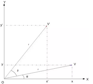
To understand this relation completely, let’s begin by understanding rotation in 2D. Let the vector V be rotated by an angle β to get the new vector V′. Let r=|V|. Then, we have the below relations:
vx = r*cosα and vy = r*sinα
v’x = r*cos(α+β) and v’y = r*sin(α+β). Expanding this, we get
v’x = r * (cosα * cosβ — sinα * sinβ) and v’y = r * (sinα * cosβ + cosα * sinβ)
v’x = vx * cosβ — vy * sinβ and v’y = vy * cosβ + vx * sinβ
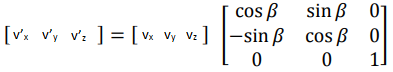
This is exactly what we want because the desired point V’ is described in terms of the original point V and the actual angle β. For conclusion we can write this in matrix notation as
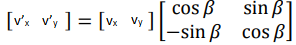
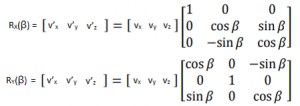
Going from 2D to 3D is relatively simple in Rotation Matrix’s case. In fact, the 2D matrix we just now derived can actual be thought of as an 3D rotation matrix for rotation around z axis. Hence, for a rotation around z-axis the Rotation Matrix would be
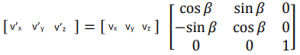
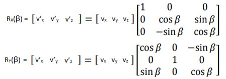
0, 0, 1 in values in last row and column indicate that z coordinates for rotated point (v’z) is same as original point’s z coordinate (vz). We will call this Z axis Rotation Matrix as Rz(β). Extrapolating same logic to rotations around x and y axis, we can get values for RX(β) and RY(β) as
And final value for 3D motion Rotation Matrix will just be cross multiplication of above three Rotation Matrices.
R = Rz(ψ) x Ry(θ) x Rx(φ), where psi (ψ), phi (φ,) and theta (θ) are rotation around z, y, and x axis respectively. - State Vector and its Derivative
As our drone has 6 degrees of freedom, we usually track it by monitoring this six parameters along with their derivatives (how they are changing with time) to get an accurate estimate of drone’s position and velocity of movement. We do this by maintaining what is often called a state vector X = [x, y, z, φ, θ, ψ, x_dot, y_dot, z_dot, p, q, r] and its derivative X_dot= [x_dot, y_dot, z_dot, θ_dot, φ_dot, ψ_dot, x_doubledot, y_doubledot, z_doubledot, p_dot, q_dot, r_dot] where x, y and z are position of drone in World frame, x_dot, y _dot, and z_dot are positional / linear velocities in World Frame. φ, θ, ψ represent drone attitude / orientation in World frame whereas φ_dot, θ_dot, ψ_dot represents rate of change of this (Euler) angles. p, q, r are angular velocities in body frame whereas p_dot, q_dot and r_dot are its derivate (derivative = rate of change) aka angular acceleration in body frame. x_doubledot, y_doubledot, z_doubledot represents linear accelerations in World Frame.
- Linear Acceleration
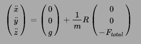
As briefed before, whenever propellers are moving, drone will start moving (accelerating) in x, y and z direction depending upon total thrust generated by it’s 4 propellers (represented by Ftotal in below equation) and drone’s orientation (represented by Rotation Matrix R). We know force = mass * acceleration. Ignoring Rotation Matrix R, if we just consider acceleration in z direction, it would be given by
Z_force = (mass * gravitational force) — (mass * Z_acceleration)
mass * Z_acceleration = mass * gravitational force — Z_force
And therefore Z_acceleration = gravitational force — Z_force / mass
Extrapolating it to x and y direction and including Rotation Matrix (for reasons described in section 4 and 6), equation describing linear acceleration for a drone is given by below equation, where m is mass of drone and g is for gravitational force. Negative sign in F indicates that we are considering gravitational force to be in positive z direction.
- Angular acceleration
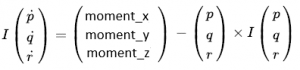
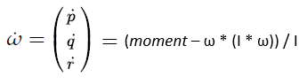
Along with linear motion, owing to rotating propellers and its orientation, drone will also have some rotational motion. . While it is convenient to have the linear equations of motion in the inertial / world frame, the rotational equations of motion are useful to us in the body frame, so that we can express rotations about the center of the quadcopter instead of about our inertial center. As mentioned in section 4, we will use drone’s IMU to get its angular accelerations. Let’s consider output from IMU be p, q and r, representing rotational velocities around drone’s x, y and z body axis.We derive the rotational equations of motion from Euler’s equations for rigid body dynamics. Expressed in vector form, Euler’s equations are written as
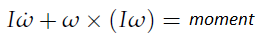
where ω = [p, q, r]^T is the angular velocity vector, I is the inertia matrix, and moment is a vector of external moment / torques developed in section 2. . Please don’t get confused with usage of ω (as angular velocity) in this section with it’s usage as propeller’s rotation rate. We will stick to usage of ω as rotation rate post this section. We can rewrite above equation as
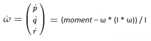
Replacing ω with [p, q, r]^T, expanding moment vector and reshuffling above equation we get angular accelerations in body frame as
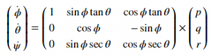
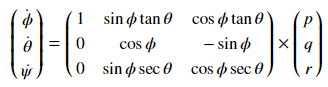
- Rate of change of the Euler angles
Although drone’s orientation is originally observed in Body frame, we need to convert them to World Frame. Again, we use rotation matrix as per below formula for this purpose. The derivation of this formula is little elongated and is provided in the Reference [6]
- Recap
So to recap what we have learnt so far
1. A quadcopter has 4 (2 CW and 2 CCW) rotating propellers
2. Each Propeller creates F =K_f * ω² force in direction perpendicular to its plane and Moment M = K_m * ω² around it’s perpendicular axis.
3. A drone can be in any x, y, z position and theta (θ), phi (φ) and psi (Ψ) orientation.
4. When a drone wants to move in z direction (in World Frame) it needs to generate appropriate force (total thrust divided by 4) on each propeller. When it wants to move in either x or y direction (again World Frame), it makes respecting theta / phi angle along with generating required force
5. When tracking drone’s motion, we need to handle data in World and Body Frames
6. To convert angular data from Body Frame to World Frame, a Rotational Matrix is used
7. To track drone’s movements, we keep track of its state vector X and its derivative X_dot
8. Rotating propellers generate linear accelerations in x, y and z direction as per equation shown in section 8
9. Rotating propellers generate angular accelerations around z, y and z axis in Body frame as per equation shown in section 9
10. We convert angular velocities in Body Frame to World Frame Euler angle velocities as per equation shown in section 10. - References
I don’t want to just list down references, but instead would like to sincerely thank individual authors for their work, without which this article and the understanding which I have gained for drone dynamics would have been almost impossible.
1. System Identification of the Crazyflie 2.0 Nano Quadrocopter by Julian Forster — http://mikehamer.info/assets/papers/Crazyflie%20Modelling.pdf
2. Trajectory Generation and Control for Quadrotors by Daniel Warren Mellinger — https://repository.upenn.edu/cgi/viewcontent.cgi?article=1705&context=edissertations
3. Quadcopter Dynamics, Simulation, and Control by Andrew Gibiansky — http://andrew.gibiansky.com/downloads/pdf/Quadcopter%20Dynamics,%20Simulation,%20and%20Control.pdf
4. A short derivation to basic rotation around the x-, y- or z-axis — http://www.sunshine2k.de/articles/RotationDerivation.pdf
5. How do you derive the rotation matrices? — Quora — https://www.quora.com/How-do-you-derive-the-rotation-matrices
6. Representing Attitude: Euler Angles, Unit Quaternions, and Rotation Vectors by James Diebel — https://www.astro.rug.nl/software/kapteyn/_downloads/attitude.pdf

I would like to sincerely thanks Bitcraze team for allowing me to express myself on their platform. If you liked this post, Follow, Like, Retweet it on Twitter, it will act as encouragement for writing new posts as I continue my journey in becoming a complete Drone engineer.
Till next time….cheers!!
Very good article! It would be even better by adding MathJax to your page, especially if you plan to make more tech articles.
https://www.mathjax.org/
Thanks for the tip!
Hello
I would like to know if you can visualise the output of the flow deck using arduino and processing.
Thank you
Hi! Please ask this question on the forum instead
A good article!
I want to translate this blog into Chinese and send it to my blog. Is that OK?
I will note the original author’s name, the original link address, or other relevant copyright instructions as required.
Sure. Can you also link to my Medium profile (https://medium.com/@percy.jaiswal) while referring to author details?
Glad you liked it, thanks.
I will. Thank you!