Base station geometry estimation is a function in the python client (in the lighthouse tab), where the system estimates the position and orientation of the base stations. The user places the Crazyflie on the floor (in the desired origin) and clicks a button to measure the angles to the base stations, which are used to estimate the geometry. The current implementation is fairly basic and has some issues associated with it:
- All base stations must be received from the point where the Crazyflie is located
- Only 2 base stations are supported
- The coordinate system is not properly aligned with the room
- The generated geometry is not as good as it could be, that is the position/orientation is sub-optimal
- The code has a dependency to OpenCV which causes problems for ROS users
I have been working on a solution for these problems as my fun Friday project and in this blog post I will tell you a bit more about the problems and a possible solution.
What are the problems to be solved?
In the current implementation, the user places the Crazyflie in the origin, with the front of the Crazyflie pointing in the direction of the positive X-axis. When the user hits the “Estimate Geometry” button, the angles to the visible base stations are recorded and the solvePnP() function in OpenCV is used to estimate their poses (position and orientation). This is all fine but it also has its limitations and in the following section we will outline what the limitations are and how to solve them.
All base stations must be received in the origin and only 2 base stations are supported
Currently the Crazyflie ecosystem supports up to 2 base stations and this works fine for a flight space of around 4×4 meters. With more base stations it would be possible to cover larger areas or multiple rooms, which is a feature that many users have been asking for. In these scenarios it will not be possible to receive all base stations from one position any more though, and it will require a new method for geometry estimation using multiple measurements. Suppose base station 1 and 2 are received in one position and 2 and 3 in another, then we can map the measurements together since we know base station 2 must have the same pose in both measurements. This way it is possible to relate all base station poses to each other, provided there are measurements that link them together.
The coordinate system is not properly aligned with the room
When generating the geometry in the current implementation, the orientation of the Lighthouse deck is used to define the coordinate system: forward of the deck defines the X-axis, left defines the Y-axis and up the Z-axis. The problem is that the deck might not be perfectly aligned with the Crazyflie, the floor might not be completely flat or the Crazyflie might not point exactly in the desired direction. A pretty small misalignment will result in fairly large errors a couple of meters away, resulting in unexpected behavior, for instance not flying at constant height. Expanding to more base stations and larger systems, the problem will become even bigger and a better solution is clearly needed.
If we used the position of the Crazyflie when placed at multiple positions, we could use this information to rotate the coordinate system to be better aligned. For instance, suppose we measured some points on the floor of the flight space, then we could make sure the XY-plane of the coordinate system goes through those points, or at least as close as possible. Similarly one or more measurements along the X-axis would help to define the rotation around the Z-axis.
The generated geometry is not as good as it could be
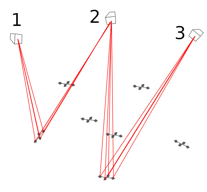
The lighthouse positioning system is based on measuring the angles between the sensors on the Lighthouse deck and the base stations. One can think of it as four beams or rays, going from each base station to the sensors on the deck, for which we measure the direction very precisely seen from the base station’s point of view. The purpose of the geometry estimation is to figure out the position and orientation of the base stations so that we can calculate how the beams are oriented in the flight space instead. By looking at where the beams from two base stations intersect we know where the sensors are located and can calculate the position of the Crazyflie. This is a somewhat simplified picture of how it works but it is sufficient for the following discussion.
So what happens if the geometry is not completely correct? If the estimated positions or orientations of the base stations are slightly off, the beams will not intersect and we have to use some method to find the point closest to the two beams instead to use as the sensor position. In a real world system there will always be errors and the implementation must be able to handle them, but we want to keep them as small as possible. Further more we want to make sure the errors are uniformly distributed in the flight space so that we get equally good results everywhere.
In the current estimation process, where we take a measurement in one position, we are able to generate a geometry that is good at that point, but due to noise in the measurements and other subtleties the error at the edges of the flight space might be several centimeters.
The solution to this problem is to measure the angles in multiple positions and try to find a geometry where the error is equally small for all of them. It does not guarantee that the error will be equal everywhere, but if we make measurements in the volume we plan to fly in we know it will be OK where we need it to be. It should also be a much better geometry, for the full covered volume, than what we can be achieved by measuring in one point only.
One bonus problem that hopefully will be solved by this approach is the moving back and forth that sometimes can be seen in a Lighthouse 2 system. What happens is that the base stations interfere with each other from time to time (by design) and most of the time the Crazyflie gets positioning information from both base stations, but every couple of seconds only from one of them. When both are available the “average” position is used, but when only one is received, the Crazyflie will “jump” to the position indicated by that base station (the simplified model from above with crossing beams does not hold in this case, sorry!). If the difference between the suggested positions of the two base stations (the error in the geometry) is large there will be a noticeable motion in the Crazyflie.
The code has a dependency to Open CV
In the current solution we use the solvePnP() function in Open CV to estimate the geometry. Open CV is an awesome library but unfortunately it has turned out that this dependency interferes with ROS, and since a fair amount of our users also use ROS, we would like to get rid of it if possible.
Luckily I found an open source implementation of IPPE, an algorithm that finds the pose of an object based on points seen by a camera, that we can use instead. There is actually an option to use Ippe in OpenCV’s solvePnP(), but we used another flavor.
The solution
The core idea is to first collect measurements of beams in many positions in the flight space by moving a Crazyflie around and record the lighthouse angles. Secondly an equation system is created that takes the poses of the base stations and all the recorded Crazyflie poses as input and as output calculates the lighthouse angles those poses would correspond to for all the sensors. Finally the output is compared to the recorded values and poses are adjusted using the least-square solver in scipy to find the poses that minimizes the difference between the measurements and the output from the equation system.
Before we can solve the equation system we have to record the angles from the base stations. There is a handy function in the Crazyflie that pushes measured lighthouse angles to the PC via the radio, and by letting the user move the Crazyflie around in space we get the angles along that path. What we are looking for though are angles collected in discrete positions and as an approximation I group measurements together based on time. The assumption is that if two angle measurements are closer than 10 ms in time, the Crazyflie did not move very far and they can be considered to be taken in the same position. The output of this process is a list of samples where each sample contains the measured lighthouse angles of one or more base stations for one specific Crazyflie pose. After this has been done, the list is filtered to only contain samples with two or more base stations.
We also need an initial guess of the base station and Crazyflie poses for the least-square solver to make the solution converge. I use IPPE for this and use the first sample as the reference to define a temporary global reference frame. Suppose the first sample contains angles for base stations 2 and 3, we can then use IPPE to calculate an estimate of the pose of the two base stations, in the Crazyflie reference frame of this sample. Since we use the first sample as the reference for the global reference frame (that is the pose of the Crazyflie in this sample is the origin by definition), those poses are also equal to the base station poses in the global reference frame.
Suppose the next sample contains lighthouse angles for base stations 1 and 2, using IPPE we can estimate the base station poses for base stations 1 and 2 in the reference frame of the Crazyflie in this sample. Since the relative positions of the base stations is the same, regardless of reference frame, we can rotate/translate the poses of the base stations so that base station 2 pose matches the pose of base stations 2 in the first sample. We now have an estimate of the poses of base stations 1, 2 and 3, further more the transformation used represents the pose of the Crazyflie in sample 2. Repeating the process for all samples gives us a pretty good idea of where all the base stations are located as well as the pose of the Crazyflie in all the samples.
We can now feed the initial guess and the equation system into scipy and hopefully get a refined solution back. From the estimated poses of the base stations and Crazyflie samples it is possible to calculate the distance between sensors and beams which gives us an approximation of how good the solution is.
The final step is to align the coordinate system with the room, as mentioned earlier the solution we have this far is based on the pose of the Crazyflie in the first sample. The way it is done in the suggested implementation is to ask the user to place the Crazyflie at some points in the desired origin, on the positive X-axis and in the XY-plane and measure the angles in these positions. The measurements are included as samples in the above process which means we will get the estimated positions as a part of the over all solution, in the temporary global reference frame. The task at hand is then to find the rotation/translation from the temporary global reference frame to the one indicated by the positions sampled by the user. Again we do a least-square optimization to find the transformation that minimizes the error in the sampled points. We can now calculate the final solution by applying the transformation to the base station poses we got earlier.
Does it work?
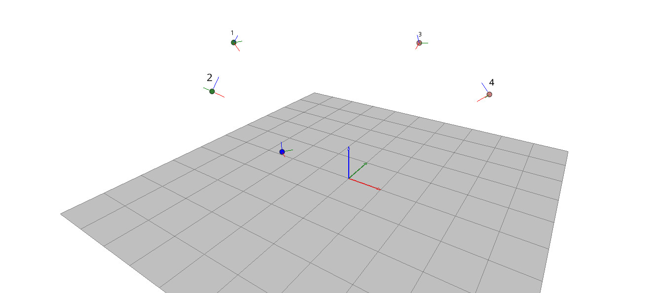
Yes, it seems to work pretty well, I have not had the time to do extensive testing yet but the results looks promising. In our flight arena with 4 base stations, the solution seems to generally be acceptable. We don’t know the exact poses of our base stations since it is very hard to measure, but they are mounted in the same truss and should be at similar heights.
Base stations at:
1: (-3.7104629351065146, -0.27330674065567867, 2.960720481536423)
2: (-0.9233909349006646, -2.9651389799486356, 2.9781503155699176)
3: (-0.12450705551081238, 3.430497907723026, 3.011201684709142)
4: (2.74012584124908, 0.5856524795079388, 3.023133069381165)
Solution match per base station:
1: {'mean_error': 0.0026020322270174697, 'max_error': 0.013310934923630531, 'std_error': 0.0028768923969783836}
2: {'mean_error': 0.0015240237742724164, 'max_error': 0.005526851773945277, 'std_error': 0.0011560341160273498}
3: {'mean_error': 0.002193101969828834, 'max_error': 0.006778096051979129, 'std_error': 0.0015768914826109067}
4: {'mean_error': 0.0033752667182490796, 'max_error': 0.014997173956894249, 'std_error': 0.00354931189334688}
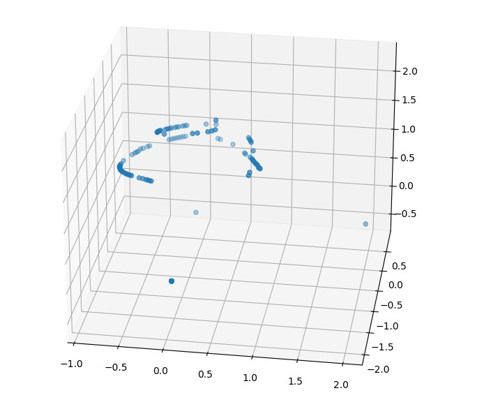
The above snippet is part of the output from one run and as can be seen the estimated height is between 2.96 and 3.02 m. You can also see that the estimated average error for sensor positions is in the order of 2-3 mm while the maximum error is 1.5 cm.
Below is graph of the recorded Crazyflie positions in the final solutions. Note the three single points at the bottom that are from the origin, the X-axis and XY-plane.
I did some testing on larger systems with 6-8 base stations this Friday and it seemed to be harder to get a solution that converges which indicates that there might be something to look into here.
Try it out
This is still work in progress, but if you want to try it out, you can find the code in this pull request. Run the examples/lighthouse/bs_geometry_estimation.py script, you will get instructions on the screen as you go.
Officially the firmware supports 2 base stations , but most of the code is designed to handle up to 16 and if you want to test the functionality with more than two base stations you have to update PULSE_PROCESSOR_N_BASE_STATIONS and re-flash your Crazyflie.
Any feedback is welcome, please use the pull request.
Excellent to see that you are continuing to improve lighthouse functionality!
Number 3 is especially nice to see help with. I had a trajectory that I wanted to run reliably for many resets of the physical crazyflie, but even with tape marker on the ground, I found it hard to reproduce to my liking.