A while ago I started working on a brushless motor control driver for the Crazyflie. I implemented most of it but did not really have time to test it. Recently we have gotten some request and questions about it so we took some time to do some further testing.
Implementing a brushless motor control driver can be done in many ways. If you have brushlesss motor controllers that can be controlled over I2C that could have been one way but usually the brushless motor controller (BLMC) take a PWM input. This is most commonly a square wave with a period of 20ms and a pulse width of 1-2 ms high, were 1 ms is 0%, and 2 ms is 100%. A period of 20 ms means a frequency of 50Hz. This is most often a high enough update rate for R/C electronics like servos etc. but when it comes to BLMC that is not the case. Therefore many new BLMC can read a much higher update rate of up to 400 Hz were the pulse still is 1-2 ms high. That way you can match the BLMC input to the update rate of the stabilization control loop and increase stability. In the code we added a define BLMC_PERIOD where this can be set.
To test this we wanted a frame which was quick to setup and found this. It is based of a PCB just like the Crazyflie and has the four motor controllers with it, perfect! The built in BLMC are based on an the Atmel MCU Atmega8 which is very commonly used in the R/C BLMC which means it is possible to re-flash them with the SimonK firmware. This is know to be a great firmware and enables fast PWM update rate etc. So we built and flashed the firmware configured for the tgy6a which is compatible and it worked right away, yay!
Now we only had to connect the Crazyflie to the BLMC:s on the frame. The BLMC electrical interface for the PWM signal is often a 5V interface but the Crazyflie runs on 2.8V. 2.8V would in most cases be treated as an high input and can probably be used directly but there is no simple way to connect this signal on the Crazyflie. Instead one way is to use the existing motor connectors and the pull-down capability that is already there. Then it is also possible to pull this signal to 5V with a resistor to get a 5V interface so this is what we did. To power the Crazyflie we took the connector of an old battery and soldered it the 5V output of the frame.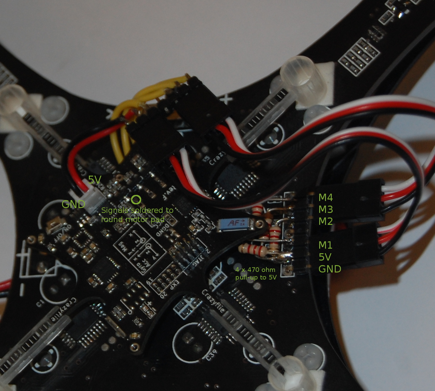
Now it was just a matter of testing it! However as size increases so does the potential damage it can make. We therefore took some precaution and tied it down. First we tested the stability on each axis using the stock values and it worked really well so we decided to not tune it further. The only issue was that suddenly one of the BLMC mosfets burnt. We replaced it and it worked again but don’t know why it burnt. Later when we flew it something was still strange so we have to investigate this.
We will upload the code as soon as it has been cleaned up. Please enjoy a short video of the journey :)
I would love to see the code, because I really need a opportunity to lift more weight. So it should be possible to carry a little camera and a bigger battery.
~20min flytime would be awesome..
Cheers Marvin
The code is available in our GitHub repo on the branch brushless_driver: https://github.com/bitcraze/crazyflie-firmware/tree/brushless_driver
There’s also more information available on our forum: http://forum.bitcraze.se/viewtopic.php?f=6&t=115
Hi there,
Great work! Pretty exciting stuff. I was wondering if you could please post up the specs of the motors, props and battery you ended up using (and if possible where you sourced them)? I’m really interested in giving this a go myself!
Thanks,
Phil
I wrote quickly about the motor setup I used in the thread. Good luck! http://forum.bitcraze.se/viewtopic.php?f=6&t=115&p=4866#p511
Hello Tobias, im thinking to try some Ducky Motors with crazyflie and brushless driver. Lets talk about it ?
Oh, im on forum now, ignore the post.