While we where in the US we finally received our long-awaited HackRF Blue. Our plan was to use it to sniff the Crazyradio and Crazyflie communication in order to be able to better debug the communication.
HackRF Blue is a lower cost build of the open source HackRF One. It is a Software Defined Radio (SDR), you can think of it as a sound card for radio. It allows to observe and manipulate radio signals from ~1MHz up to 6GHz within a maximum bandwidth of 20MHz. We use it with GNU Radio on the PC which is a signal processing library that contains all we need to do using SDR. Gnuradio has a nice GUI, the Gnu Radio companion, that allows to start testing without having to write code (this GUI actually output a Python program). Getting into SDR is not easy, we have been looking at the Michael Ossmann’s SDR videos (I suggest you look at them if you want to learn about SDR!) and it helps a lot understanding what to do. In this post I will try to briefly explain the step to detect and decode the Crazyradio nRF24 signal. We wrote an howto in the wiki if you want to set up an nRF24 sniffer.
To test the HackRF I just created a very simple python script that sends 10 packets per seconds with Crazyradio:
from crazyradio import Crazyradio
import time

cr = Crazyradio()
cr.set_channel(26)
cr.set_data_rate(cr.DR_1MPS)

while True:
    cr.send_packet((0,1,2,3,4))
    time.sleep(0.1)
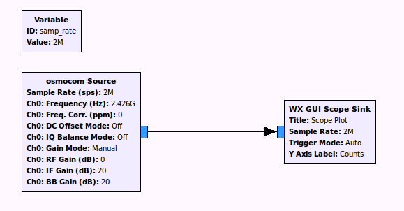
Then we just tune HackRF to the Crazyradio frequency, and we can see the GFSK signal!
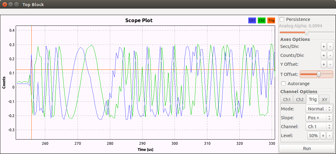
GFSK is a kind of Frequency Modulation. Which means that it should be a cosine wave of constant amplitude. So calulating the magnitude of the complex signal allows to locate data packets by setting the scope trigger:

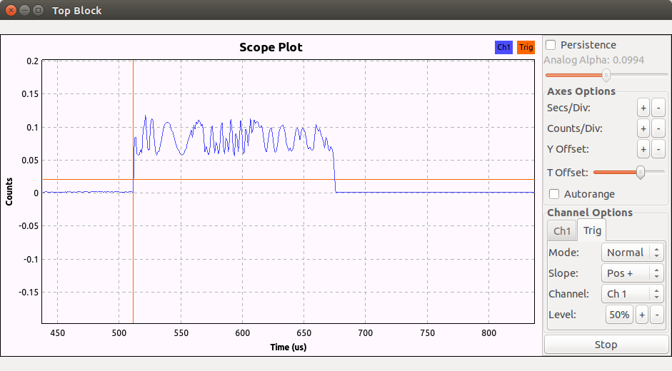
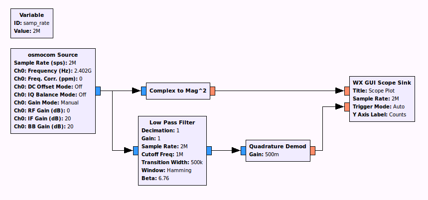
Now that we can synchronize on a packet, we can add a filter and a quadrature demodulator to demodulate the fm signal and show the data packet (in green):
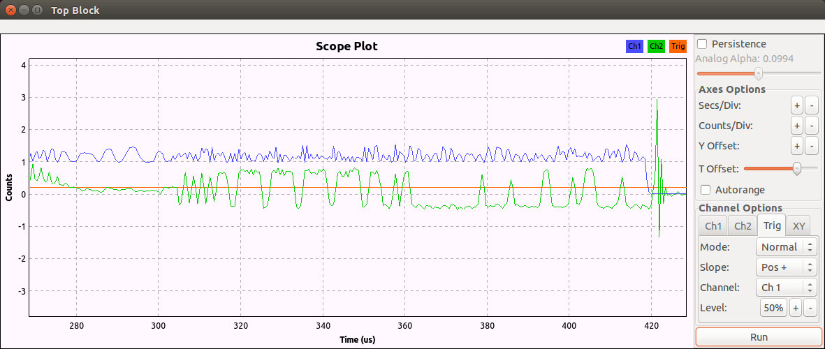
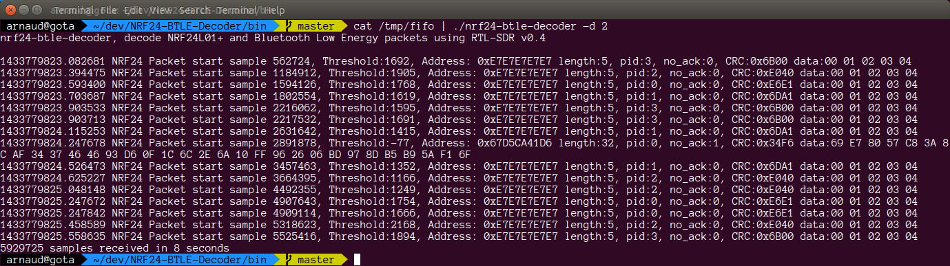
The preamble (series of 0101010101) is clearly visible followed by the radio address which is 0xe7e7e7e7e7. Now the ‘only’ things left would be to decode the packet. Hopefully for us Cyber Explorer already did the hard work and all we have to do is to send the demodulated data in a unix fifo and send the fifo in the decoder. This procedure is explained in the wiki. As a result we receives the packets:
As a conclusion we found that with the current setup we have a lot of packet lost. We also have a sniffer made out of an nRF51 evaluation kit and it gets much more packets so it is still preferred to analyse protocols. However we can still enhance the SDR algorithm and the 20MHz bandwidth of the HackRF will allow us to sniff on many channels at once, making it perfect to debug channel hopping when we implement it for the Crazyflie.
Hey, very nice article. I’m trying to sniff data from an XN297 (nRF24 clone), but running into some issues. (It’s a drone).
When I use exactly the same grc setup like you, I just get a lot of random spikes all over the place (the first grc already)! And I didn’t even turn the drone controller on. How come you see the cosine wave so clearly and I don’t?
Hi Martin, Do you mean that you haven’t turned ON the transmitter? You need to turn on the controller to have a chance to see the signal, the random spikes are normal this is noise. You also need to make sure that you are close enough to the transmitting frequency (the hackrf has a 20MHz bandwidth but the nRF can transmit in a 125MHz range).
I also have an nRF24 with Arduino, so I figured I’d first give that a try. I keep sending messages at channel 26 from the nRF, and I get a nice spike in the FFT Sink at 2.4257, but the Scope sink doesn’t show a nice cosine like yours. It does occasionally jump up and down, but that’s just for a millisecond or so. It DOES detect the nRF, but not consistently and with such a cosine :/
Ah, it looks like I did manage to get a cosine now. Will try the follow-up steps now ;) Thanks so far!
Alright so I managed to get it to work, but I’m not getting consistent output when running the decoder at all. I’m getting the idea that I’m not receiving the packages correctly for some reason (the cosine isn’t pretty and doesn’t show very often.. mainly noise). Also, how did you know the address is 0xe7e7e7e7e7 just from the cosine? The data the decoder is giving me is like this:
1469092232.277075 NRF24 Packet start sample 2697101, Threshold:4254, Address: 0x49994A299D length:8, pid:1, no_ack:0, CRC:0x9060 data:6D A8 42 AC 92 62 15 C1
1469092233.963550 NRF24 Packet start sample 6067541, Threshold:-2360, Address: 0x69554AAAAD length:22, pid:2, no_ack:0, CRC:0xCCAF data:D6 94 B5 55 5B 2B D6 AB 6C A9 5A B4 AD 6B DA 95 DA B7 55 57 77 FB
1469092235.203272 NRF24 Packet start sample 8550385, Threshold:-857, Address: 0x96D2EAAAB6 length:29, pid:2, no_ack:1, CRC:0x2ADB data:2C DA 38 B7 0D 2E 49 DC B9 AC BA 72 E7 29 69 26 AA BF 4D B9 4C C6 99 6E A7 B4 A6 75 4F
1469092235.669475 NRF24 Packet start sample 9479401, Threshold:37, Address: 0x7B9B595798 length:10, pid:1, no_ack:1, CRC:0xB254 data:11 68 A9 92 CE 18 6C DE 98 82
1469092235.786139 NRF24 Packet start sample 9722024, Threshold:-2432, Address: 0xB97B97BA7B length:22, pid:3, no_ack:1, CRC:0x5F2E data:77 53 A9 AA BA 57 7B 37 33 1D AE 4E 95 E3 F7 5D F7 55 EE D6 F9 77
This could be noise, you can see one noisy packet in my screenshot and the address is random.
From the 3rd plot in the article the E7 sequence is visible, E7 E7 is 1110 0111 1110 0111 in binary and this looks like the sequence just after the preample.
If you are sending packet with your Arduino using the 0xe7e7e7e7e7 address you should be able to look at similar packet being demodulated. For testing, it is easier to work with known packet like I did (you can see in my screenshot that I only sent packet containing 00 01 02 03 04).
Do you manage to synchronise on one packet and observe the demodulated signal?
Just be sure:
– From time 305us to 315us (approx.) is the preamble?
– Package is the part from 315 to 350?
So how are you reading this graph? I find it hard to read 1110 or 0111 from those tiny bumps, but maybe that’s just me :P. Anyway, I changed my address to 0xe7e7e7e7e7 as well and the message to ‘123’. If I stop the plot quickly, I sometimes get a cosine that looks quite similar to yours (like in your 3rd plot). So that’s good. The blue line however (channel 1) stays flat. Not sure if that matters. My Arduino program looks like this: https://codeshare.io/tUIpE
For some reason I get only noise, and not even 1 successful package :/
Ah I found out how to read the binary. Stupid of me that it took so long >.>. However, I’m still experiencing issues with retrieving the data from the decoder :/
Okay so I AM still struggling with the translation of the plot into binary. I’ve uploaded an image with the part I don’t get: http://i64.tinypic.com/2gwgoz8.png
Hi, this is a serial communication and so the time is important: the bits are sampled (ie. read) at regular interval. The preamble allows to synchronize the receiver. I made a drawing in inkscape to show the decoding: https://goo.gl/XnHfsC. If you want to play with the file this is the original you can edit: https://goo.gl/lkVYK4.
Ah, very nice! Thank you so much :). I applied it on my own cosine and it matches up. Another question: Why can we just see the address and not also the message following in the plot?
Also, is there a way to decrease noise so I can better catch the actual signal? Because I still can’t seem to demodulate it and retrieve the message. Could it have to do with the fact that I have an nRF24L01+ instead of a regular one?
Ah, scratch the question about the ‘message’ – because it IS there haha.
Alright so just out of curiousity, I’d like to decode the package message manually (also because I don’t really understand the nRF24 decoder script yet). The message after the address is as followed (https://drive.google.com/open?id=0B9CJ42CGPiF2YnhuX0hWMG1fVUk):
CE 26 80 30 80 39 00 3..
The ‘message’ I sent was “Martijn”, which is indeed 7 bytes long. (last 2 bytes are CRC I guess). How would I go about decoding this message?
Ahhh, apparently the address is followed by one extra bit. I’ve now succesfully identified ‘martijn’ as the message, yay! https://drive.google.com/open?id=0B9CJ42CGPiF2TWoyelRmWldZcU0
My remaining questions are:
– What are the ‘CC’ and the highlighted ‘0’ after the address?
– I still can’t get the live decoder to work >.< Do you have any suggestions left for me to try out?
Hi, Great job so far decoding in the dark :-). I assume you have not looked at the Nordic nRF24L01 product specification? On page 28 the packet format is documented and there is a 9 bit control field (the CC plus one bit). This contains the payload length (6 bits) the packet ID (2 bits, is incremented for each packet) and the no_ack flag (1 bit) that is set to 1 if no acknowledge is requested.
One reason for the decoder not to work might be that you do not seems to be exactly at the right frequency: the signal is never crossing 0 while on my graph it was right around 0. For this graph the value of the signal actually corresponds to a frequency difference from the channel frequency. Since your signal is always positive it seems that you are not tuned exactly on the right channel but one up or one down.
Thanks! I now understand the packet format :).
About the decoder: I’ve tuned the frequency to better line up with the 0, but I’m still not even receiving one package :/
I set the address to 0xe7e7e7e7e7 on my nRF but as you can see, it doesn’t pop up at all (while I DO see packages coming by in the plot!):
https://drive.google.com/open?id=0B9CJ42CGPiF2dXYyOTE3aFlpNjg
For the decoder I’m using the GRC setup from the wiki (https://wiki.bitcraze.io/_media/misc:hacks:grc_nrf24_demod.png), but I’ve also tried playing with the Quadrature Demod gain, sample rates, etc. – no result.
Could it be that I should tweak the decoder in some way? For example, I think I’m not using any CRC.
My arduino code atm: https://codeshare.io/ptMHb
Could you maybe show me how I could binary slice the data and put that into a file, instead of the fifo way?
I can’t find any good documentation on how to use the binary slicer. The file gets huge once I try..
I am not sure what you mean by binary slicer? If you want to send the data in a file instead of the fifo you can just change the filename in the file sink block. I have not written the nrf24 decoder so I am not sure how it works and why it is not working for you.
HI,arnaud
Could you explain how the ‘quadrature_demod’ can be used to demodulate the fsk signal?
I search a long time in google, but there is any useful information about it.
Can you give me a hand?
I’m having the same issues as mentioned by Martin – completely random addresses in the decoded NRF24 data.
Hi, I have read your article and it is very interesting. I want write a python script to detect a drone syma X5SC-1 (NRF24L01) with HackRF. I don’t need decode information, only produce a warning on screen like “drone detected”. Can you help me with de python script? If it is possible send me information about this. Thanks.