Ever since we released the Alpha round of the Loco positioning system we’ve been talking about designing a more generic tag that could be used together with other robotics platforms for local positioning. We did a quick design of a prototype that we tested, but with the workload involved in bringing the LPS out of Early Access, finishing the Z-ranger and lots of other stuff , it’s remained on the shelf. But recently we’ve been getting more and more requests for this kind of hardware, so we thought it might be time to dust off the prototype and try to release it. One of the blockers (except workload) has been that we’re not sure how the tag should look mechanically and how to interface it electrically for it to be as useful as possible for our community. This post is for detailing the current status of the hardware/firmware and to see if we can get some feedback on what our community would like the finished product to look like.
The hardware
To make use of the firmware that’s been developed so far for the Crazyflie and the Loco positioning we aimed at making something similar to what we already have but with another form factor and slightly different requirements. As you might know the Loco positioning node can be configured as a tag, but there’s two drawbacks that we wanted to fix. First of all the Loco positioning node might be a bit big to put on smaller robots. Secondly the Loco positioning node can only measure the distances to the anchors, it doesn’t have an IMU to get attitude of the board and doesn’t have the processing power to run the same algorithms we have on the Crazyflie 2.0.
So for our Loco positioning tag prototype we decided to fix these. The prototype has the same sensors as the Crazyflie 2.0: Gyro, accelerometer, magnetometer and pressure sensor. It also has the same MCU as the Crazyflie 2.0: STM32F405. In addition to this it has the DWM1000 module for the ultra wide-band radio (used for positioning). We’ve also added the interfaces we have on the Crazyflie 2.0: SWD debugging, micro-USB for communication and power as well as a button. Looking at the pictures below you might also notice that we’ve added the Crazyflie 2.0 deck connector. So does this mean you can connect it to the Crazyflie 2.0? No, well not this prototype at least. The reason for adding it was we wanted to be able to use the same expansion decks as for the Crazyflie 2.0. So it’s possible to add the breakout deck for breadboard prototyping or the LED-ring for visual feedback.
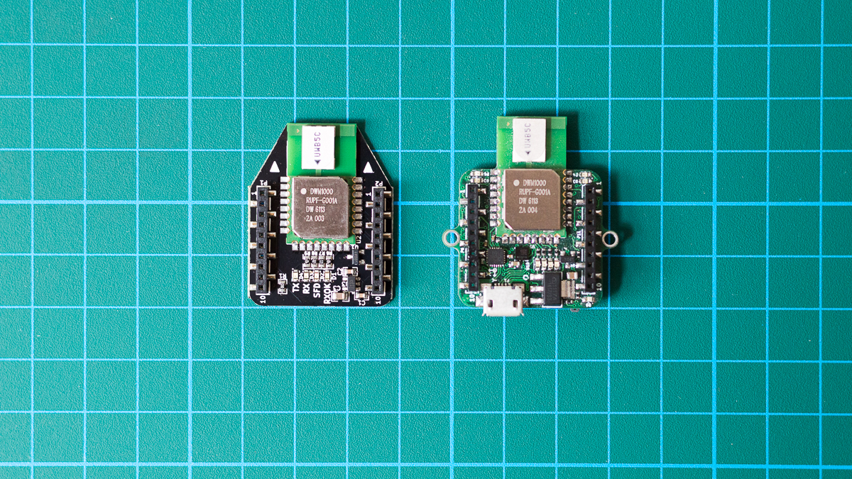
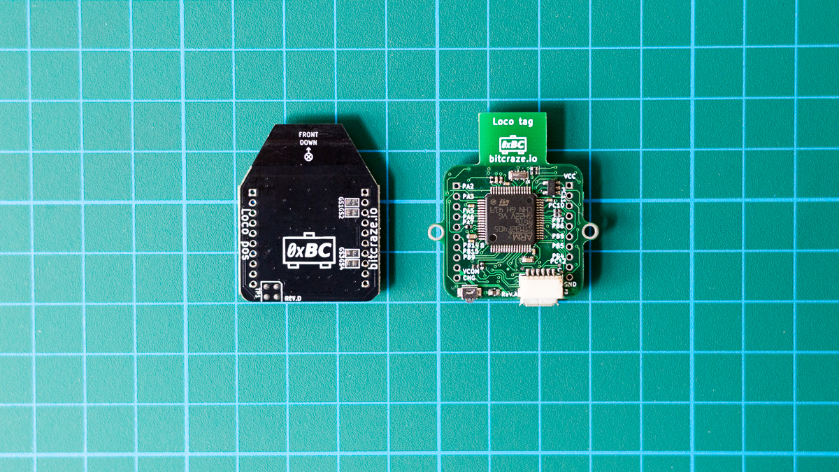
So what’s the status of the hardware? Even though it’s the first prototype it’s fully functional and will give you positioning and attitude. What’s left is defining the electrical interfaces and the form-factor of the board so it can easily be attached to what ever you might want to track. The images below shows a side-by-side comparison with the current Loco positioning deck.
Loco positioning tag (on the right) compared to Loco positioning deck (on the left) (FRONT)
Loco positioning tag (on the right) compared to Loco positioning deck (on the left) (BACK)
The firmware/software
Like I wrote above we wanted to reuse as much of the firmware and software as possible. So the firmware running on the prototype is just a scaled down version of the Crazyflie 2.0 firmware. As you might have noticed the prototype looks a lot like the Crazyflie 2.0, except that it’s not a quadcopter and doesn’t have the nRF51 radio. So by “scaled down” I mean we’ve removed the motor and radio drivers, that’s about it. So how do you communicate with it? Well you can use one of the protocol available on the deck connector: SPI, I2C or UART. But the currently implemented way is using USB. Since it’s basically a Crazyflie you can use our client and python libraries to set parameters and log data values from it.
Conclusion
The current prototype is basically a USB dongle where you get position and attitude. It could easily be connected via USB to a Raspberry Pi, Beaglebone or any other SoC based platform or a computer. You can also interface it from an Arduino using the peripherals on the deck connector. The firmware is working and using the python library (or any other of our community supported libraries) you can easily get the position and attitude of the board. But to be able to take the next step and make something our community could make the most of we would love some feedback on the prototype. What kind of electrical interfaces and form-factor would you like?
This looks very exciting. For me the ability to connect to a larger flight controller such as the Pixhawk would be attractive. A UART interface which looks like a standard GPS with NMEA protocol might be a quick way to integrate with devices which already use positioning.
Apologies if these questions are already answered elsewhere on your site:
Although this is an indoor wireless device do you have any outlook on it being licensed for use outdoors (in Europe)?
Does it have any capacity for user data across the link between base stations and tags?
Hi Nicholas,
Good idea with the NMEA! Interfacing via the UART to for instance Pixhawk would be great, but the question is what connector to use. Since the board should be small we can’t have too many of them. One option could be to have an expansion deck with more connectors for interfacing with different platforms.
Yes, the UWB link can carry data. For TWR mode today we carry the anchor positions as well as timestamps for calculating the position.
As for the licensing, as long as the transmission power is bellow a certain power threshold, there is no special license required for the 802.15.4 UWB radio we use.
Hey guys, is there any news regarding this PCB? It looks really neat and I’d be highly interested in getting a couple of those as I have to stick to the more bulky loco anchor PCBs for the time being.
I also support the idea proposed by Nicholas from above, having a simple way to connect directly to the actual UART – when you don’t want to use the micro-USB jack – would be nice!
Are those UWB UART signals broken out on the header in the current design?
Hi Philipp,
Glad to hear that you’re interested in the design. Unfortunately there’s not been any progress on it since the post, we’ve been really focused on the other aspects of the LPS. But we have been discussing the specification a bit and we’re planning on adding VCC/GND/UART_RX/UART_TX on a 2.54mm connector. We’re also planning on keeping the expansion connector and roughly the same size (if possible).
If you have any other suggestions or comments please let us know.
If you’re interested in getting early access to a prototype (once there is one) drop us an email at contact@bitcraze.io with a note saying so and we’ll let you know.
Hi everyone, I know this blog is a few years old now but by chance has there been any progress on this? I’d be very interested in something like this for my quadcopter, as with Phillipp above I’ve been working with the bulky LPS nodes and would benefit from something like this.
Hi! This product has been released for a while already. You can find the product page here: https://www.bitcraze.io/products/loco-positioning-deck/