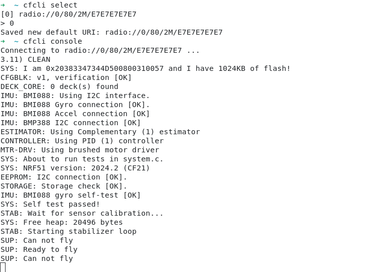
About a year ago I started working on a Crazyflie CLI (command line interface), with the goal of having a utility for quickly doing simple interactions with the Crazyflie from the command line. Initially I was mostly interested in the console, but realized that it’s neat to also be able to check some logging variables and set some parameters as well. With the new release of the Crazyflie Rust lib I’ve also updated the cfcli to be able to access the memory subsystem, along with some other nifty updates to make it easier to use.
Below is a full list of the updates in the release:
Improved user interface
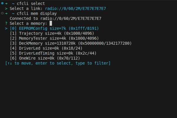
Use interactive selection if command line parameters are missing (like what params to set or which memory to display)
Animation while connecting
Added access to memory subsystem
Raw access to memories
Initialize, erase and display decoded information from EEPROM and 1-wire memories
Configure the Crazyflie EEPROM (i.e set channel, address, speed etc)
Set and get multiple parameters at once
Generate and flash DeckCtrl configurations via debug probe
Bumped all dependencies
If you would like to give it a try just run cargo install cfcli. Have a look at the crates page or the GitHub repository for more information and feel free to leave any suggestions or comments below. Here’s a short video showing the new interactive selection being used:
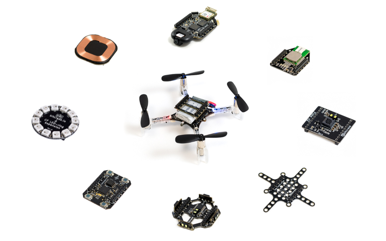
At Bitcraze we like making decks! When we released the Crazyflie 2.0 we were really excited about the new deck connector we put on the platform. Using this, it was suddenly possible to expand the platform, adding new, more complex functionalities years after the initial release. It’s something that we really like about the Crazyflie. Over the years we’ve released a bunch of decks and also updated a few of them as new, improved sensors became available.
Deck limitations
As the number of decks has increased, along with their complexity, we’ve started noticing some limitations. We’ve touched on this a while back in this blog post where you can find more details, but here’s a short summary:
Resource sharing in the STM32F4: Mainly DMA conflicts between different peripherals, like conflict for DMA using DSHOT on the Crazyflie 2.1 Brushless and the WS2812b driver for the LED-ring.
Bus arbitration and performance: Some decks make excessive use of some buses, which can cause issues with certain combinations like the LPS deck and micro-SD card deck.
Deck combinations and pins: As more interesting decks are released and we’re able to carry more weight, users want to combine more decks. Although we try to be smart with pin allocation there’s a limit on how you can combine the decks.
MCUs on decks: As the complexity increases, separate MCUs are also included on the decks. Although working well for offloading the main MCUs on the Crazyflie, the complexity quickly increases both for usage and for development. This is something we’ve seen with the AI deck for instance, which contains 2 MCUs.
Like suggested in the original blog post, the solution will be to move more intelligence onto the decks by putting MCUs on them. These MCUs can then use the hardware on the decks without sharing resources with the main Crazyflie MCU and can also help process the data to make the communication with the Crazyflie more high level. But doing this will of course then make the issue raised in the last point even worse. To mitigate this we need to have better control over the decks. Our proposed solution for this is adding a new MCU to the decks which acts as a controller. Being able to switch on/off power, bootstrap and control various aspects of the deck. Some of the features include:
Uniquely identify the deck and also identify the model of deck – This will replace the current 1-wire memory subsystem we have today
Uses minimal amount of pins, basically only using the I2C pins
Use the MCU pins as GPIOs or as various peripherals:
GPIO expander enables switching on/off onboard power supply, simplifying bootloading and saving power. It also enables bootstrapping of onboard MCUs, which can be used for selecting what output pins to use for various functionality
Bridge I2C to SPI/UART for bootloading of onboard MCU. This would of course be much slower than using the SPI/UART but would simplify bootloading and not need pins allocated on the expansion connector
Bootstrapping the board makes it possible to to implement support for duplicate decks, for instance selecting what UART (1 or 2) on startup makes it possible for the driver on the Crazyflie to start up each deck and select what UART is used.
Our implementation
For our implementation of this system we have selected the STM32C011 MCU, as it comes in various packages from very small to slightly larger, so it’s possible to solder by hand. It also has the features we needed. To maximize the the flexibility of the system we don’t want to program in the I2C addresses in production. Even if you disregard the fact that the address might conflict with other I2C devices in the future, it will definitely conflict if you add two of the same type of deck.
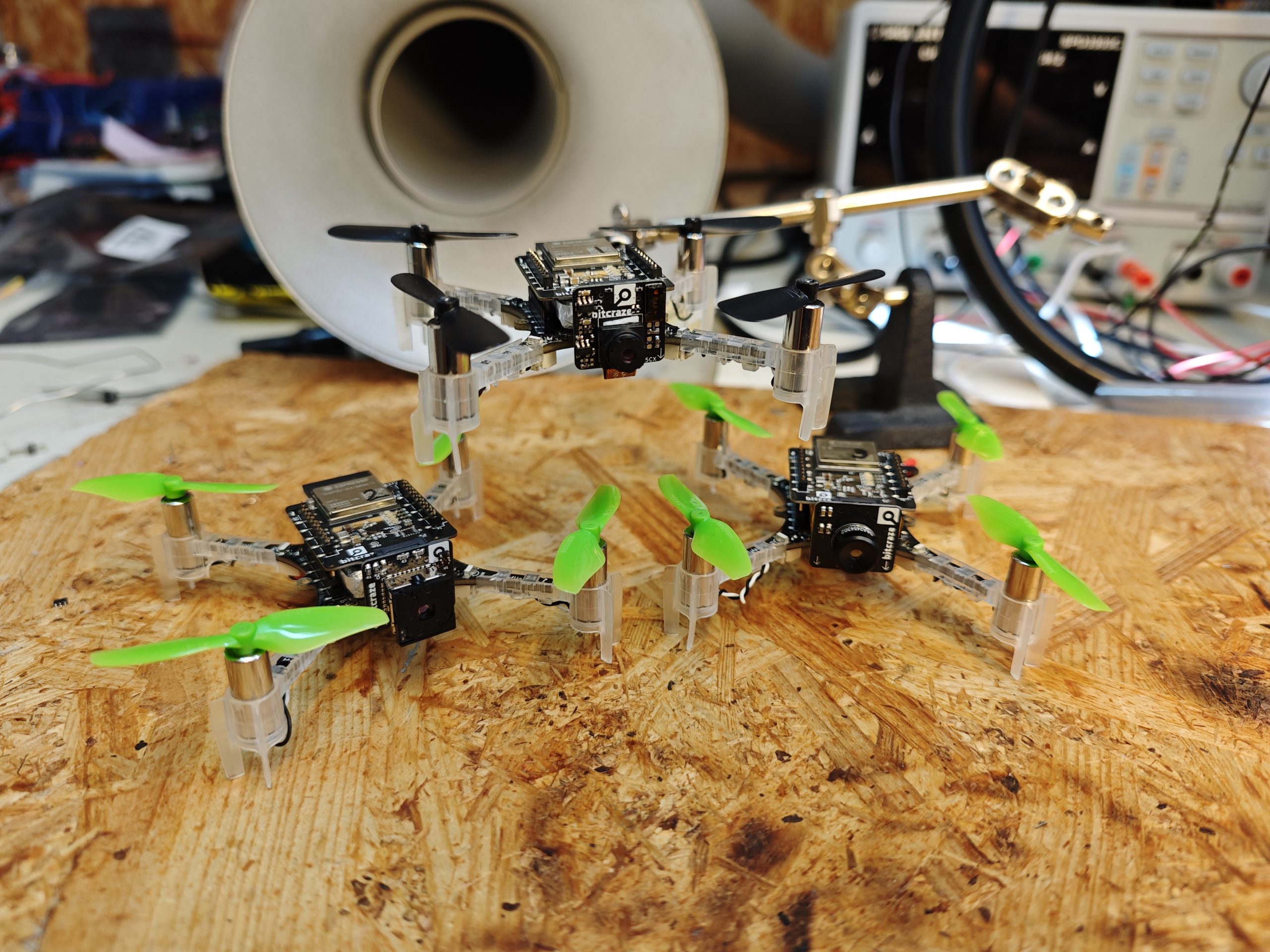
To fix this we will automatically detect all the deck-ctrl MCUs on the bus and then move them to individual addresses. This will enable us to change the addresses in the future if there are collisions and also allows multiple instances of the same deck attached at the same time. Below is a video demonstrating this in action, implemented on custom development decks we’ve made for simplifying firmware development. Each deck runs the same deck-ctrl firmware and all 3 are auto-detected at startup.
The future
The current solution will be used on our next two upcoming decks: the new LED deck and the new Lighthouse deck. As we get closer to their release we will publish the firmware for the deck-ctrl MCU on GitHub. If the design turns out well we will keep rolling it out to future decks, increasing the flexibility of the deck expansion system even more.
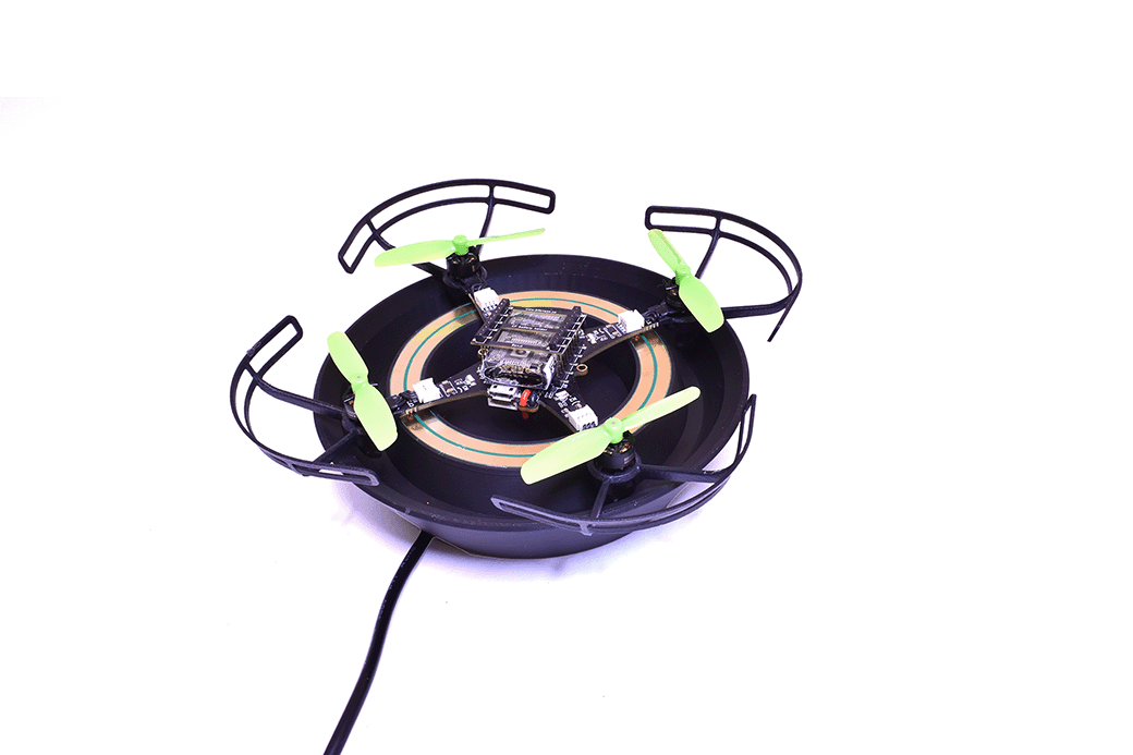
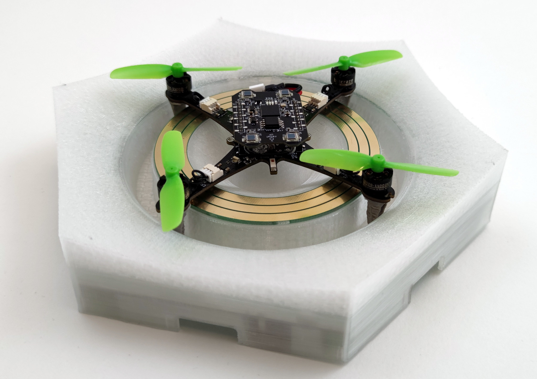
While planning for the Crazyflie 2.1 Brushless release we also decided to make our charging dock available to our users. We wanted our users to be able to make the same kind of demos we were making in our lab and showing off at fairs. To make this happen our 3D printer has been working around the clock the last couple of weeks, churning out as many charging docks as possible. And now we’re finally ready to put some in stock ? So make sure to check out the Charging dock in the E-store if you want to keep your Crazyflie 2.1 Bushless ready to fly at all times!
The charging dock is the same version we use in our flight lab, you might have spotted it in previous videos (like this one from last week). It’s also the dock we will be using our for swarming demos at fairs (like this one) in the future. Compared to the Qi deck, using this solution we save a lot of weight as well as maintain the possibility of having downwards-facing decks (like the Flow) mounted.
Although the main usage is for swarming (with autonomous takeoff/landing) you can also use it as just a charging dock, placing it here each time you’ve done some flying in the lab. This ensures that your Crazyflie is prepared for the next round of experiments.
If you’re interested in seeing a bit of history, have a look at some of our older blog posts about the charger. From the first prototypes, passed a fancy version with LEDs and WiFi and finally ended in the currently more sleek version we have today.
Ever since we started going to fairs to show off the Crazyflies, we’ve been trying to push the boundaries for the demos. Often we’ve used the fairs as an opportunity to either develop new functionality or try out new ideas. Something we’ve always been interested in, especially for fairs, is autonomous flights. It’s hard to talk to people about the Crazyflie while trying to fly it at the same time. Back in 2015 we were using the Kinect for piloting the Crazyflie at the Bay Area Maker Faire. Although awesome, we had a slight issue: we needed to switch batteries on the Crazyflie each flight. We had a Qi deck for wireless charging but no positioning system good enough to use it for landing on a charger.
Latest iteration of the Crazyflie Brushless charger
In 2018 we were really excited when we got to borrow a motion capture system from Qualisys and could finally land on a Qi charger (3D printed base and an IKEA Qi charger). First time we showed this off was at IROS in Madrid 2018. The following year we improved the demo to have more Crazyflies and switched to the Lighthouse positioning system at ICRA 2019. Since then each year we have been improving the demo until we’ve reached the current state we showed off at IROS 2022 in Kyoto.
So since 2018 we’ve been using the Qi wireless charging for our demos. Many customers have purchased the Qi charging deck, but building a matching charging platform has always required some effort. So, a while back we started looking at something that could replace the Qi deck, with a lighter solution which would also allow users to have other decks with electronics facing downwards. The first prototypes were made with the Crazyflie 2.1 back in 2021 using decks, but they were a bit clumsy. For one thing you needed the charging solution to be integrated on each deck.
When work started on the Crazyflie Brushless we realized we had the possibility to integrate the charge points directly on the main PCB which meant we could still use any decks we wanted and get the charging. So the prototypes from 2021 were reshaped into something we could use with the Crazyflie Brushless. Although the prototypes worked well, they were pretty big and packed with features which weren’t needed for charging (like LED lights and WiFi). Another iteration and the chargers have now gone down in size and complexity. The latest iteration only has charging and is powered via our 12V power block or 5V USB-C.
Over the years lots of customers have asked us for buying the Qi charger, since many users do not have the capabilities to build their own. Unfortunately we’ve never gotten around to it, but with the release of the Crazyflie Brushless we would like to change this. The release is only a few months away so we’re short on time for remaking the design so it’s usable for plastic molding. Instead the plan is to make a limited amount of prototypes available to our users, based on the same 3D printed design and electronics we’re currently using in our flight lab, at the time of release. This will enable our users to easily try out the design and create their own autonomous demos which will keep flying for a long time.
As you might expect, we use the Crazyflie python client a lot at Bitcraze. The client has a lot of features, ranging from setting up LPS/Lighthouse systems to turning on/off the headlight LEDs on the LED-ring deck. But some of the features we use the most is probably the console view as well as the logging/parameter subsystems. A lot of the time we modify firmware, flash it and want to tweak (via parameters) or to check if the changes are working as expected (via the console or logging). Then switching from the terminal, where we build/flash, to the Qt UI in the Crazyflie python client can be a hassle if you just want to do something quick. It would be great to be able to log/set variables directly from the terminal, well now you can!
Meet the Crazyflie command-line client, a fun Friday project I worked on a while back. The CLI is written in Rust and was made possible thanks to a previous fun Friday project by Arnaud on the Rust Crazyflie link/lib, which has now moved to the official Bitcraze repositories. The CLI project is still very limited, but has some basic functionality:
Scan for Crazyflies and pre-select one to interact with
List loggable variables, create log configurations and print their value
List parameters and get/set them
Show the Crazyflie console
Last week the first version, v0.1.0, was released on crates.io. So if you have Rust set up on your computer and want to test it out then all you need to do is to type “cargo install cfcli“. The CLI still only has some basic functionality, but hopefully it can be expanded in the future with more useful things! Feel free to leave any issues or comments you might have on the Github page.
A great feature of the Crazyflie is its ability to keep evolving, both by using software but also through hardware expansions. Hardware expansions allow us and our users to keep exploring new problems and doing new experiments, without having to change the flying base. Over the years lots of new decks have been released and we’ve seen lots of users building their own custom electronics and attaching it to their Crazyflies. Although very versatile, the current deck system is limited to up/downwards facing expansions. Adding electronics that face forward, like a camera, has been harder and has required additional mechanics. Over the last couple of months we’ve been experimenting with a new expansion connector aiming at solving this issue. The idea is to be able to add a new class of expansions facing forward. This week’s blog post and next week’s developer meeting are about these experiments.
Goals and design
We’re always trying to find ways to make our platform more versatile, making it easier to expand and to be used in new ways. So we’ve been looking for a new way to be able to expand the platform even more, this time with electronics facing forward instead of up/down. The goal is to easily be able to add things such as cameras, ranging sensors etc. Making a custom deck with custom mechanics for each sensor hasn’t been a good solution, it takes lots of time and it doesn’t enable our users to do their own custom electronics. Finding a generic solution is hard since we’re constrained both in space and in weight. We need a solution which is very small and light, each gram adding cuts into the flight time. The solution also needs a way to handle the data generated from cameras/sensors as well as possibly to stream it over a faster connection than the Crazyradio.
Our current prototype is made of two parts, a new deck with WiFi and more computational power as well as several smaller expansions which can be added to it. The expansions fit straight into a small right angle connector, making it easy to change boards. The current connector we’re testing has 30 positions, of which 6 is used for power and 1 for 1-wire, leaving 24 pins for signaling. The 1-wire works the same way as our current decks, additional added hardware is auto-detected at startup and can be used without recompiling or reconfiguration.
The current prototype uses an ESP32-S3 and weighs in at 3.7 grams. Added to this there are a number of expansions that we’re evaluating:
OV2640 + VL53L5CX: RGB camera and ranging sensor (1.6 grams)
Flir Lepton 3.5: Thermal camera (2.1 grams)
MLX90640: Thermal camera (2.0 grams)
So the current prototype with RGB camera (and ranging sensor) weights in at a total of 5.3 grams (0.9 grams more than the AI deck).
Current status and continuation
We’re currently experimenting with connectors, modules and dimensions. In the coming months we will try to get more flight time to test the solution and we’re hoping to get some feedback from our users. So please post any comments and/or suggestions you might have.
If you’re interested in knowing more and discussing this then join our developer meeting next week on Wednesday. We will also be showing off the prototypes at ICRA, so make sure to swing by the booth if you’re attending.
If you haven’t seen it yet then check out our latest Christmas video! In it, we show off a bunch of new stuff, with the main ones being the new Crazyflie brushless and the Lighthouse V2 (which supports up to 16 base stations). But there were also a few other things featured in the video! One of them is the charging pad the Crazyflie brushless takes off from and lands on in the video. This weeks blog post is about the charger, how it came to be, how it works and what lies ahead.
Some history
A while back I worked a bit on a contact charger for the Crazyflie 2.1. The idea was to try and make a design where small pogo-pins could be added to various decks which would allow the Crazyflie 2.1 to charge when lading on a charging pad. Some of the issues with the design was that the area was small (it had to fit on a deck), it put requirements on each deck and that some decks (like the Flow V2 deck) has components which are taller than the pogo-pins. So after the blog post back in 2021 this has been on the shelf, until recently when the Crazyflie brushless work has been moving forward.
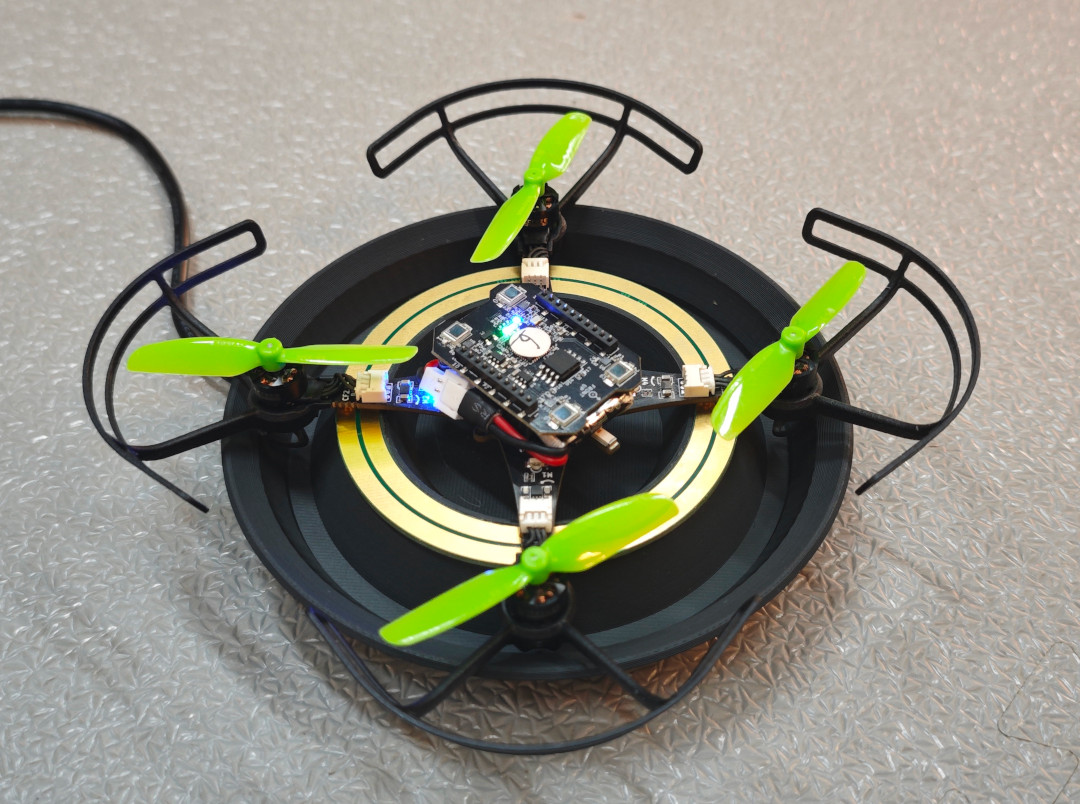
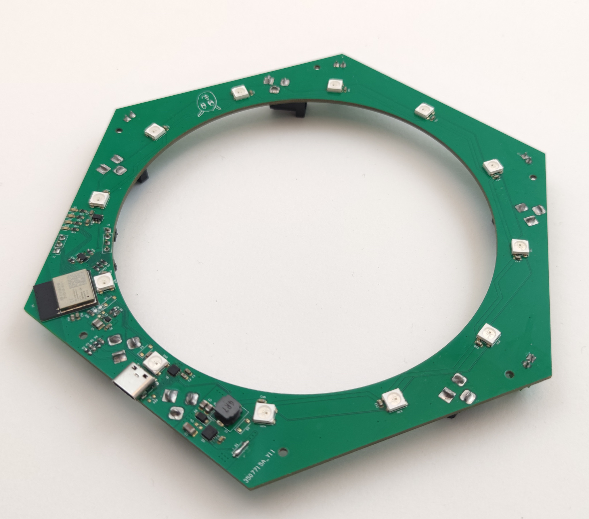
With the new prototype design for the Crazyflie brushless being made, there was a chance to address some of the issues I’ve seen before and do another try. All we needed was to add some pads for soldering pogo-pins on the wings (which actually wasn’t as easy as one would think due to layout constraints). So now the charging points didn’t have to be on each deck, they are built into the Crazyflie BL base. The distance between the points is also larger, allowing for a bigger hole in the charging PCB and allowing for a higher variety of decks, like the LED ring with the diffuser shown in the video.
The last missing part of the puzzle was when we needed to do more flight testing with the Crazyflie brushless. We wanted to reproduce the infinite flight demo we previously had for the Crazyflie 2.1, but the current Qi charger pad didn’t work with the new Crazyflie brushless. Time for the next iteration of the charger prototype!
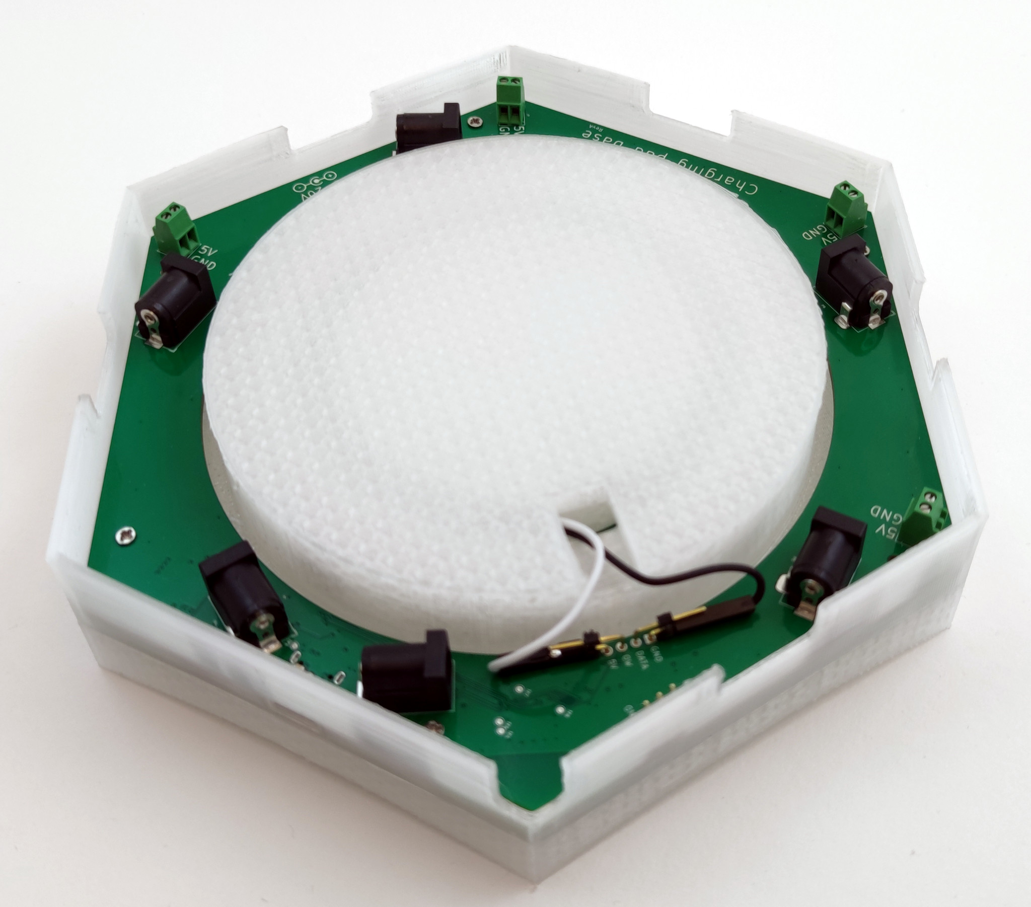
Under the hood
So how complex can you make a charger? Lots! When making a prototype I like to add as much ideas possible to the design. Missing something you wanted to test and doing a new version takes a lot of time but adding some extra crazy ideas might be pretty quick in the design phase. A lot of the time ideas are scrapped along the way, most of the time because of space- or price constraints. Sometimes they are just bad or too complex. Luckily in this case the charger has a large PCB with lots of space and it’s just an early prototype so there’s (almost) no bad ideas!
Under the hood (or 3D printed plastic in this case) there’s a bunch of stuff:
An WiFi/BLE module, the ESP32-C6-MINI
USB-C connector
USB-PD controller
6 DC-jack connectors and 5 terminals for connecting power
Measurement of charging current and supply voltage
12 WS2812B RGB LEDs for the outer ring and 12 for the inner one
20-to-5V DC/DC and 5-to-3V3 DC/DC
Some debugging LEDs and UART
Intended use
The idea with the contact charger has been to easily charge your Crazyflie without disconnecting the battery, plugging in the micro-USB connector or blocking the use of decks facing downwards like the Qi charger does. In addition to this I also wanted to try out some other ideas.
WiFi: For a long time I’ve had a prototype of a server for connecting various hardware to (like a charger) so I wanted to try to connect it to this for monitoring.
BLE: The idea was that the Crazyflie could talk to the charger via BLE to for instance change the light effect.
LEDs (and lots of them): The idea was to give some feedback from the charging of the Crazyflie but also to give the charger the ability to act as something more, like lighting up when a Crazyflie decides to land on it.
USB-PD: This is connected to the chaining of power. The ideas was to connect a USB-C charger and distribute the power from it to other chargers via the DC-jack.
Rust: Like we’ve written about before, we’ve been trying out more and more Rust here at Bitcraze. This is yet another experiment, the firmware for the charger is written in Rust using Embassy.
Future
Currently the charger is an internal project, since we use it in our lab for the infinite flight. But it’s of course something that would be exciting to offer our users if there any interest. So let us know what you think!
Also, don’t forget to join us for this Wednesday’s dev meeting. the main topic will be about the Kalman filters however we can answer questions about the wireless as well!
For this months developer meeting we will be discussing the increasing complexity of the deck subsystem, talking about the challenges we see moving forward as well as discussing some possible solutions. In the blog post this week I’ll be discussing the first part, some of the challenges moving forward.
After releasing the Crazyflie Nano Quadcopter back in 2013 we realized we wanted something more than the small expansion connector we placed there. Sure, it was possible to attach more electronics (and we did) but mechanically, electrically, and software-wise it was a hassle. So when we got around to working on the Crazyflie 2.0 in 2014 we were really happy with the new expansion connector. The goal was to offer users new hardware solutions as they became available as well as giving the possibility to create customized hardware configurations. It supported multiple buses, different heights for the decks, top and bottom attachment, automatic detection, and last, but not least, it held the battery in place. Initially, we released a few decks, but over the years there have been many more. Some are very simple, like the breakout, and some are very complex, like the AI deck.
Although we’re still very happy with the deck subsystem, we’re starting to see some challenges moving forward as deck complexity increases. Some of these issues are:
Resource sharing in the STM32: Mainly DMA conflicts between different peripherals, like conflict for DMA using DSHOT on the Crazyflie Bolt and the WS2812b driver for the LED-ring.
Bus arbitration and performance: Some decks make excessive use of some buses, which can cause issues with certain combinations like the LPS deck and micro-SD card deck.
Deck combinations and pins: As more interesting decks are released and we’re able to carry more weight, users want to combine more decks. Although we try to be smart with pin allocation there’s a limit on how you can combine the decks.
MCUs on decks: With increased complexity also comes separate MCUs on decks. Although working well for offloading the main MCUs on the Crazyflie, the complexity quickly increases both for usage and for development. This is something we’ve seen with the AI deck for instance, which contains 2 MCUs.
The challenges above are something we discuss from time to time around the office, often ending up at a whiteboard pitching various ideas. The most popular solution (and therefore the most likely one becomes reality) is moving complexity off the Crazyflie and onto MCUs placed on the various decks. This would probably solve most of the challenges with the first three points, but obviously worsen the last point above.
So the question quickly becomes, how do we work with multiple decks with one (or more) MCUs without the situation becoming too complex? Something often heard in embedded is that for each MCU added the complexity grows exponentially. From experience, we can say that this isn’t so far off.
With the new Crazyradio 2.0 out, discussions on new protocols, the possibility of a library rewrite, new deck prototypes and more payload capabilities, it’s becoming more clear how this would fit in. We still haven’t decided on what solutions we’re using, but we do have a bunch of ideas that we think would fit together to meet these challenges moving forward. On Wednesday I’ll continue to discuss some of these challenges in our monthly developer meeting and also discuss some of the suggested solutions. We’re also more than happy to hear comments about this from our users. If you’re interested in joining the discussion you will find the link here. We hope to see you there!
Bolt DSHOT support for ESCs configurable via Kconfig
ESC pass-though configuration via USB (virtual COM port)
For more information (and files for the release) see the release notes and files on GitHub, the releases of the different projects are listed below. As always, we’re really eager to get feedback, so let us know if you try it out and how it works!
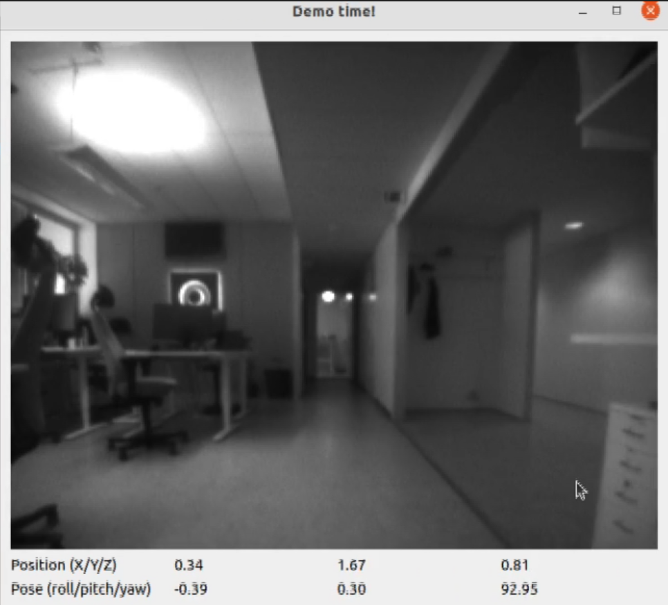
Before the summer vacations, I had the opportunity to spend some time working on AI deck improvements (blog post). One of the goals I set was to get CRTP over WiFi working, and try to fix issues along the way. The idea was to put together a small example where you could fly the Crazyflie using the keyboard and see the streamed image along the way. This would require both CRTP to the Crazyflie (logging and commands) as well as CPX to the GAP8 for the images. Just before heading off to vacation I managed to get the demo working, this post is about the results and som of the things that changed.
Link drivers
When using the Crazyflie Python library you connect to a Crazyflie using a URI. The first part of the URI (i.e radio or usb) selects what link driver to use for the connection. For example radio://0/80/2M/E7E7E7E7E7 selects the radio link driver, USB dongle 0 and communication at 2Mbit on channel E7E7E7E7E7.
While working on this demo there were two major things changed in the link drivers. The first one was the implementation of the serial link (serial://) which is now using CPX for CRTP to the Crazyflie. The usecase for this link driver is to connect a Raspberry Pi via a serial port to the Crazyflie on a larger platform.
The second change was to add a new link driver for connecting to the Crazyflie via TCP. Using this link driver it’s possible to connect to the Crazyflie via the network. It’s also possible to get the underlying protocol, the CPX object, for using CPX directly. This is used for communicating with for example the GAP8 to get images.
In the new TCP link driver the URI starts with tcp:// and has either an IP or a host name, followed by the port. Here’s two examples:
tcp://aideck-AABBCCDD.local:5000
tcp://196.168.0.100:5000
Comparison with the Crazyradio PA
So can WiFi be used now instead of the Crazyradio PA? Well, it depends. Using WiFi will give you larger throughput but you will trade this for latency. In our tests the latency is both larger and very random. In the demo I fly with the Flow V2 deck, which means latency isn’t that much of an issue. But if you were to fly without positioning and just use a joystick, this would not work out.
The Demo!
Below is a video of some flying at our office, to try it out yourself have a look at the example code here. Although the demo was mostly intended for improving CPX, we’ve made use of it at the office to collect training data for the AI deck.
The Crazyflie with AIdeck during over WiFI controlled flight.
Improvements
Unfortunately I was a bit short on time and the changes for mDNS discovery never made it it. Because of this there’s no way to “scan” or discover AI decks, so to connect you will need to know the IP or the host name. For now you can retrieve that by connecting to your AI-deck equipped Crazyflie with the CFclient and look at the console tab.
A part from that there’s more improvements to be made, with a better structure for using CPX (more like the CRTP stack with functions) in the library and more examples. There’s also still a few bugs to iron out, for example there’s still the improved FPS and WiFi throughput issues.
IMAV 2022
Next week from 13th to 16th of September Barbara, Kristoffer and Kimberly will be present at the international Micro Aerial Vehicle Conference and Competition (IMAV) hosted by the MAVlab of the TU Delft in the Netherlands. One of the competitions is called the nano quadcopter challenge, where teams will program a Crazyflie + AI deck combo to navigate through an obstacle field, so we are excited to see what solutions will come out of that. If any of you happens to be at the conference/competition, drop by our table to say hello!