Previously we have been using off the shelf scales and other methods to measure characteristics, such as thrust or efficiency, of the Crazyflie products. We thought it was time to build something that is easier to use, more repeatable and tailored to our needs. Well, this has been on our wanted list for a long time, already back from when we did the RPM-deck. It was however first when Wolfgang visited us this winter that he nudged us over the edge so we finally allocated some time for it. We started off by buying some load cells and breakout boards to do something simple as a start, so we could at least measure thrust more easily. We actually started looking for off the shelf thrust stands but could not find anything suitable for the Crazyflie’s size. As is often the case here at Bitcraze, the project grew. Already before we had any load cells up and running I was designing a deck with RPM sensors, load cell amplifier and power meter. Now with the objective to easily do system identification. Therefor we named the deck the system-id deck.
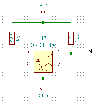
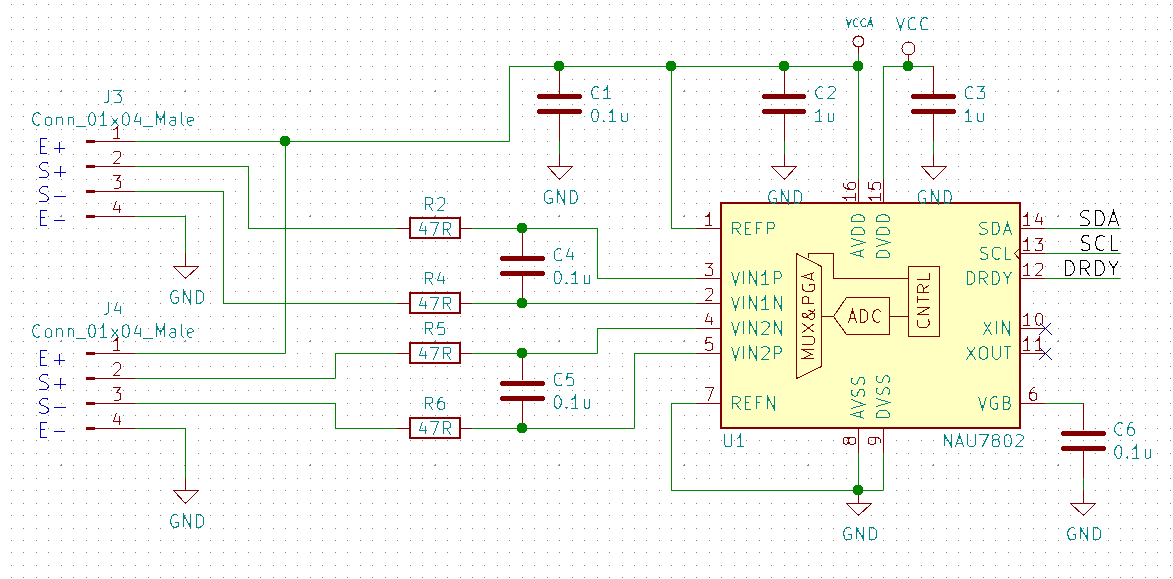
For the RPM sensors we used the same as on the RPM-deck, the QRD1114. They are not great as they need a reflective surface, this means adding white stickers or paint to black propellers, but they work well enough. The load cell amplifiers ended up to be the NAU7802 as it has a high accuracy and sample rate. For power metering we chose the new ACS37800 power monitoring IC that can handle up to 30A, this looked exiting.
The QRD1114 we wired the same way as previously done on the RPM-deck:
The NAU7802 was configured as per the datasheet suggestion and similarly to other open designs out there:
The ACS37800 was very new so the datasheet had to be used as the main information source. A bit tricky as this chip is mainly intended to measure mains supply, and we wanted to measure low voltage DC, which it said it could do…and in the end we managed to get it working.
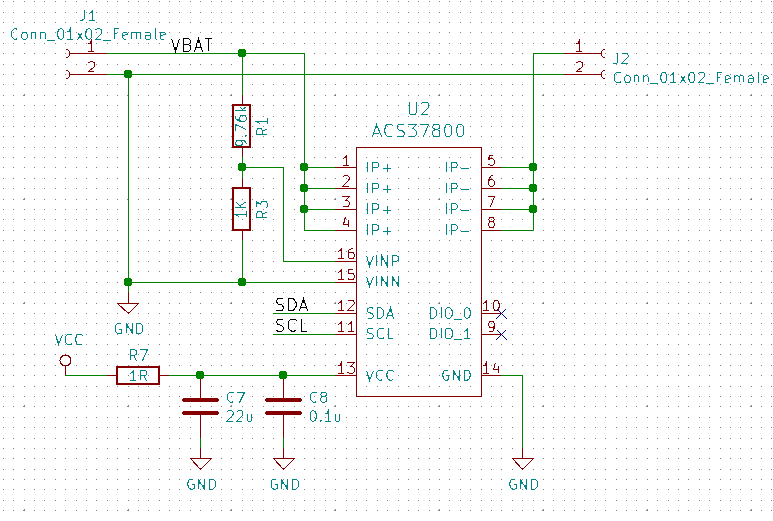
We also added a buck/boost DC/DC that could provide a stable 3.3V from 2-5V input, just in case, as the ACS37800 is specified for this voltage and not the 3.0V the Crazyflie can supply.
The outcome
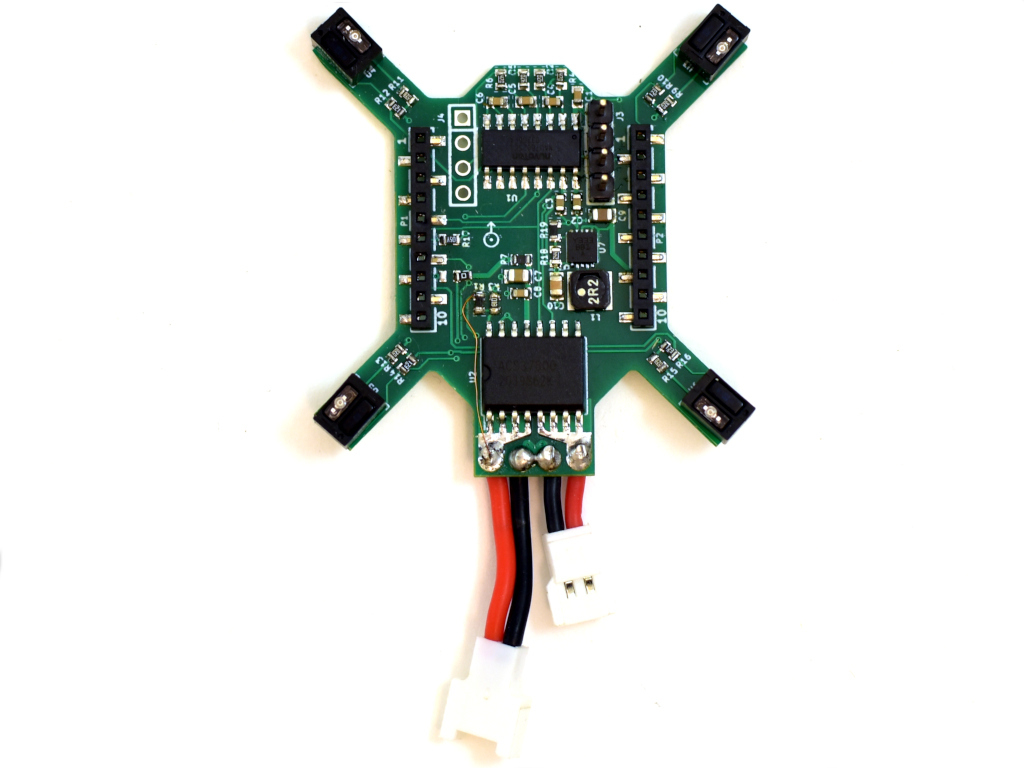
The PCB was designed as small as possible so it could be mounted on a Crazyflie 2.X and used while flying. A bonus would be if it could be used on a Bolt as well.

Here it is mounted on a Crazyflie 2.1 together with a 3D printed stand and load cell.
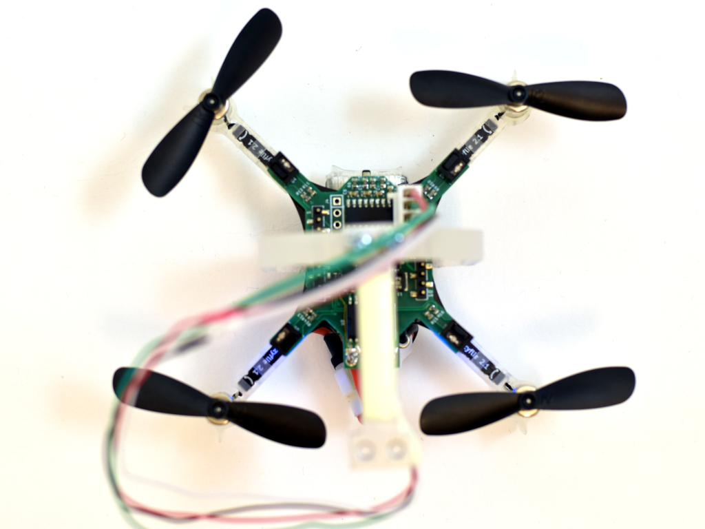
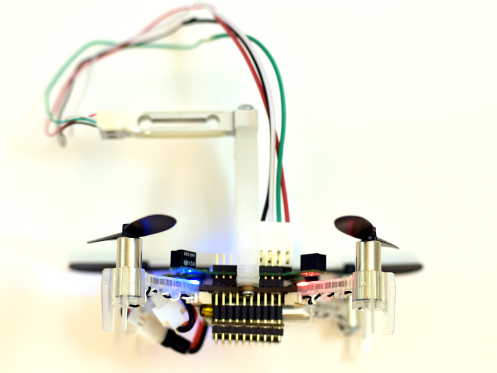
The load cell would then be mounted to a desk or similar so the the Crazyflie is mounted up-side down, pushing down on the load cell.
Software
The software, as often, took most of the time to make. Three major deck driver files was created, rpm.c, acs37800.c and loadcell_nau7802.c. Aside from these there where only small changes to make, like making it work when being up-side-down. The modifications have all been pushed to the dev-systemid branch for those that are interested. As for now we are mainly using the logging framework to transfer the data to the PC, which is quick and easy to setup and use, but writing to SD-card is also possible. The scripts for this can be found in the tools/sytem_id folder.
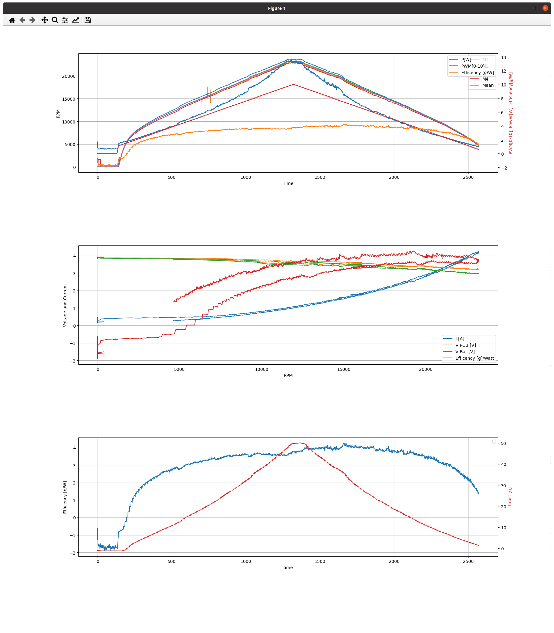
Remaining work is to test, gather and analyse more data. When we have done so, we will post more. Until then below is a sample of what it can measure. The data is taken with a ramping PWM from 0% – 100% – 0%. The added resistance of the extra wires and connectors are not taken into account, but the estimated efficiency of 4g/W is probably not that far off.
Hello.
I am a master’s student who is doing research using Crazyflile at Sejong University in South Korea.
I want to conduct research using this product.
Can you sell it?
Or I want to know how to make a PCB board.
Thanks
Hi! We do not sell this thrust stand deck unfortunately. If you have any questions about it, it would be better to send us an email, and we can come back to you in the next few weeks, as quite few of us are still on holidays.
Also, do you mean that you want to know how to make ‘a’ generic PCB board or this particular PCB board?
Hi,
I was wondering if there is more information available about the “only load cell” test. I’m interested in measuring force using different PWM signals. I found that we can directly connect the load cell to GPIO pins of Crazyflie and log the force values, but not clear how?
Also, is the STL file for the 3D printed stand available anywhere? I checked https://github.com/bitcraze/bitcraze-mechanics , but couldn’t find the model.
Thanks!
To measure the signal from a load cell you need a high precision AD converter, like the NAU7802 we use in this blog post. If you have that there is a driver for it to read out the values. It might not be straight forward though.
There should be a FreeCAD file for the stand in the repo.