During the preparations for BAM, for example the awesome demo that Kristoffer did (link to demo), we had a lot of discussions about landing on charging pads. The Qi deck is a good solution, but the design is a bit complex and makes it hard to have other electronics pointing dowards (although we’ve seen some solutions to this). So after spending a few days thinking about this, I set out to spend a few fun Fridays looking at solutions for this. The results (so far) are detailed in this post.
Contact charger and decks
The idea I decided to try out was something we’ve been discussion on-and-off for a few years, using contact charging instead of Qi. So I revived a few of our old ideas and starting looking for parts. This is always a fun phase of an idea, the sky is the limit! I’m kind of used to electronic parts, but I find looking for mechanical parts is a lot harder. I don’t really have the vocabulary for this and all the parts look the same size in the product photos…
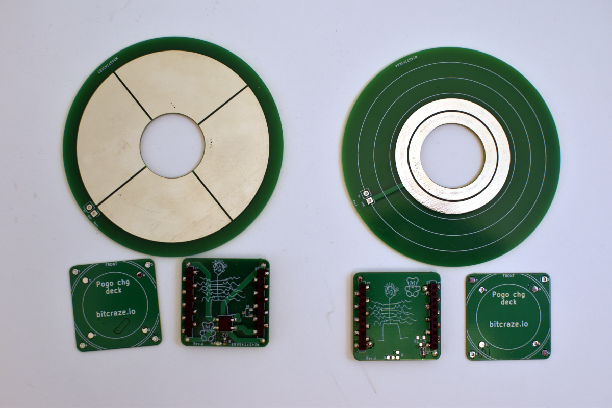
Finally the solution I wanted to test was using small pogo-pins. The idea is that the pogo-pins could be included into any design of new boards and easily enable charging. With the parts found and the ideas fresh again, I jumped into KiCad (5.99) and started the design. Two different designs were made, pictured below.
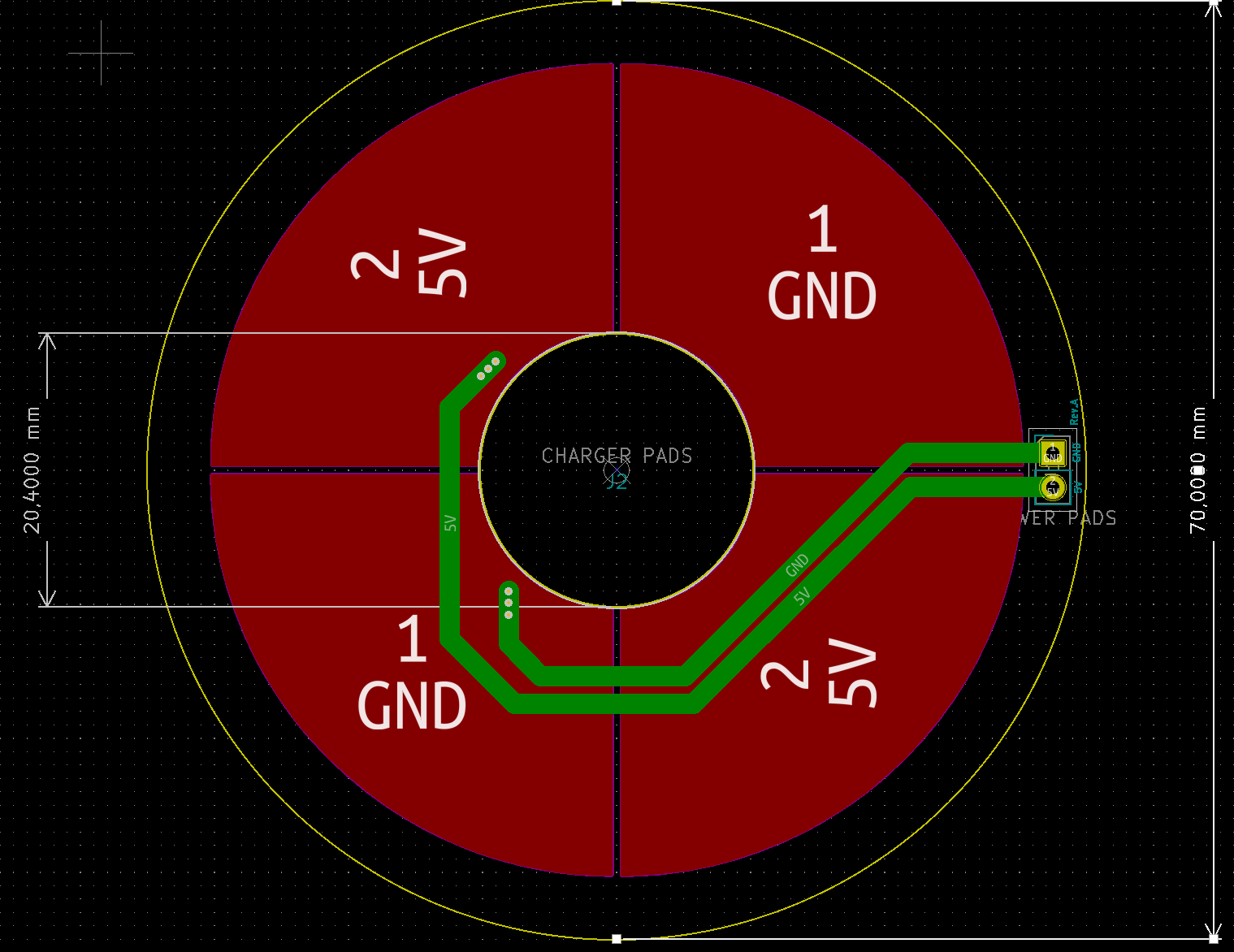
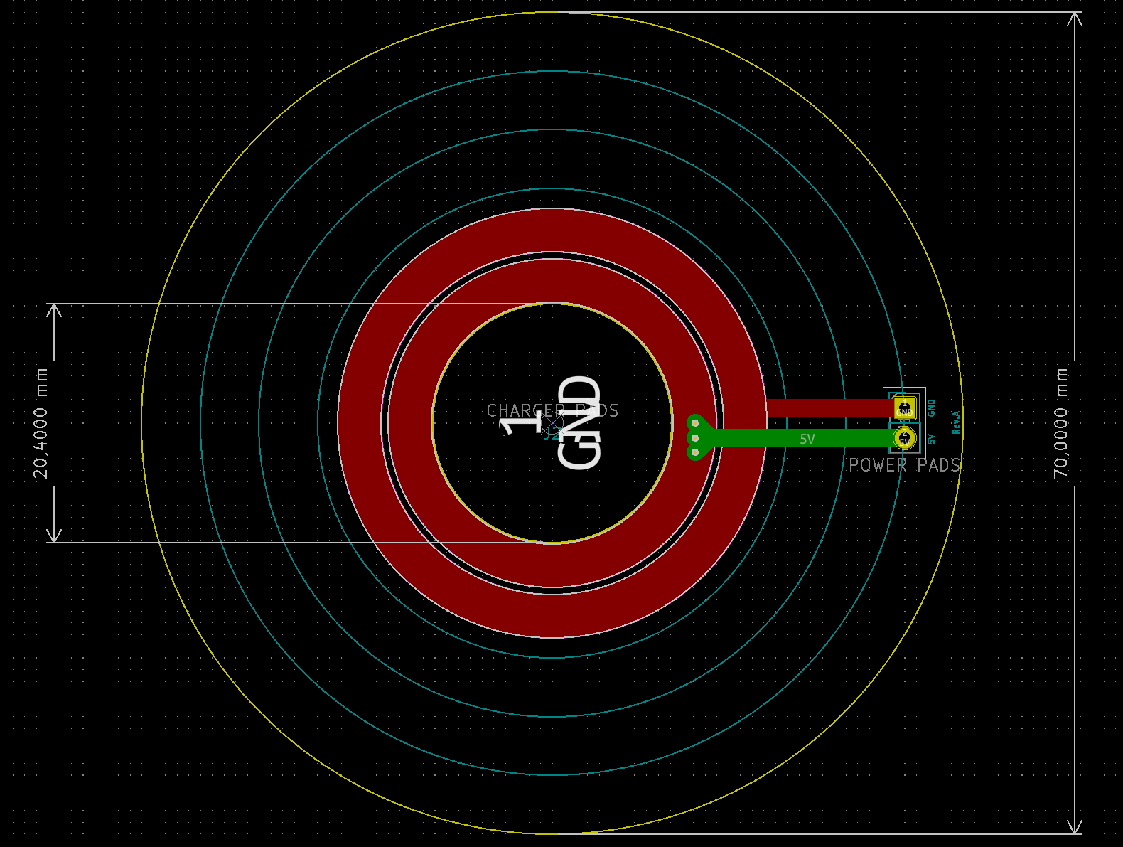
Why two solutions? I wasn’t sure which one would work well. I suspected the 4 segments would be better, but I was hoping for the two circles, since you would not need additional electronics to handle 5V/GND switched depending on how you landed.
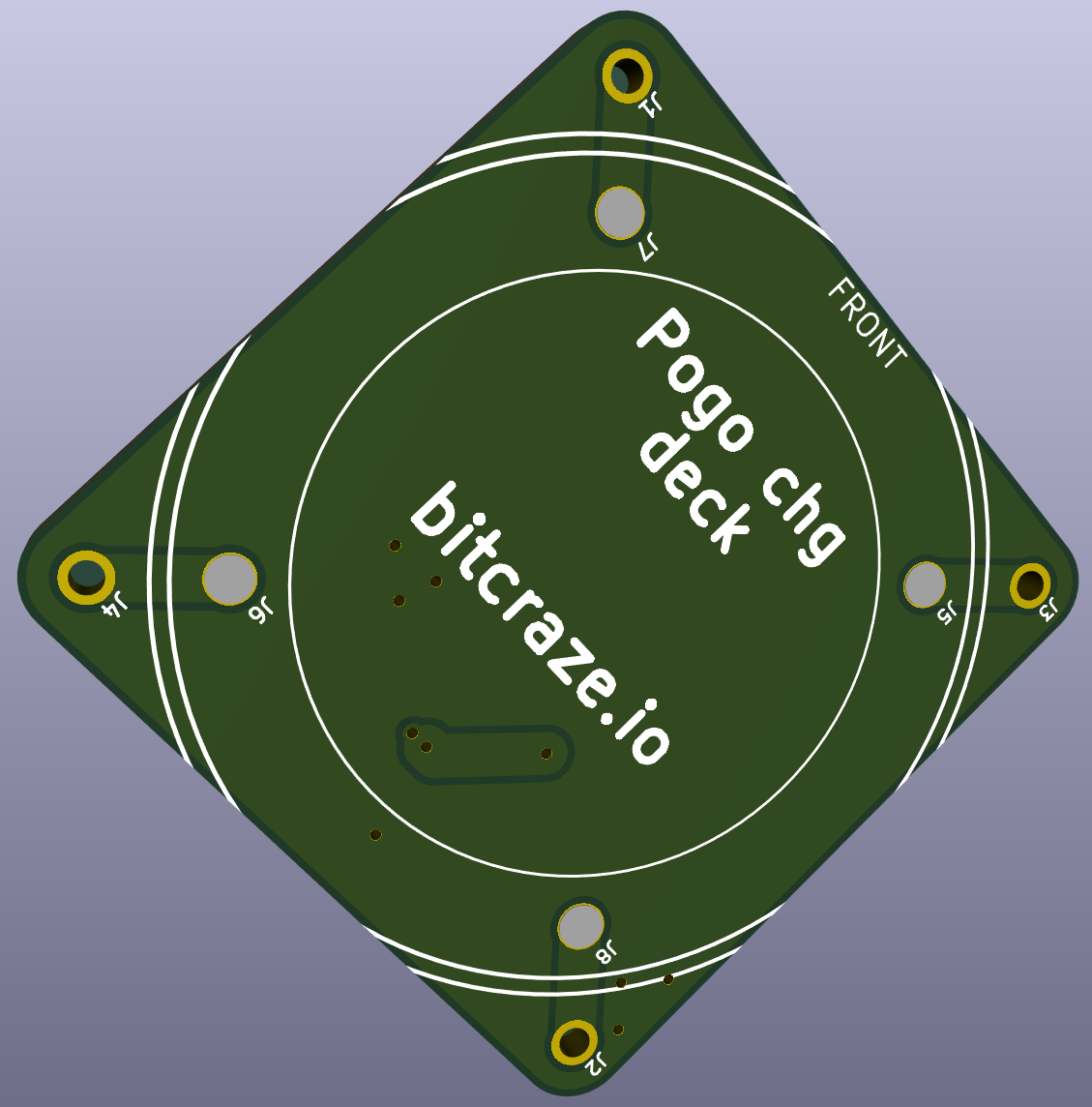
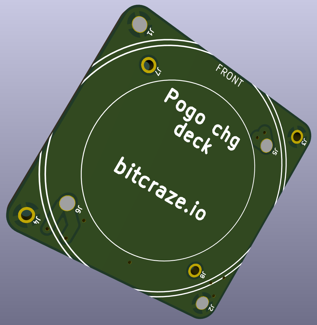
Since there was two solutions for the pad, there’s also two solutions for the deck. I wasn’t sure about what pogo pins to use, so there’s two different sets of pins (which makes it a bit confusing).
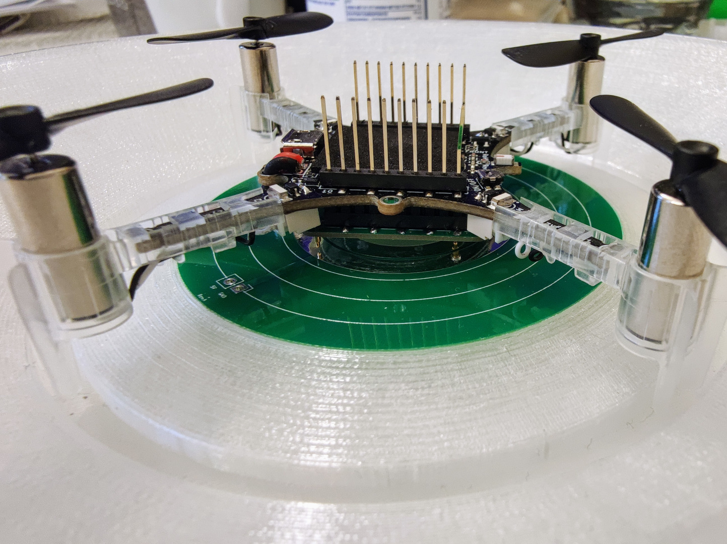
With the components and PCBs in hand I started testing, and…the results were not promising. The design was made to work with our current Qi charging pad (link). Although the alignment for Qi is important, the tolerance was not as tight as what I needed. Back to the drawing board, this time the mechanical one. I used FreeCAD to create a new version where the Crazyflie would align better. After a few iterations with the 3D printer I ended up with this:
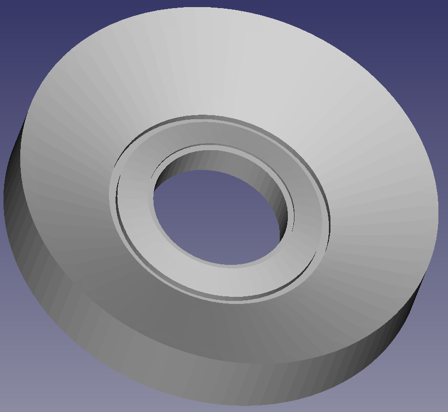
Putting it all together, the results were promising. With the new mechanical design the area the Crazyflie can land in is larger and the alignment much better. I think it’s good enough to show that the concept can work. The next step is to look a bit more at the pins, they might be a bit too easy to damage.
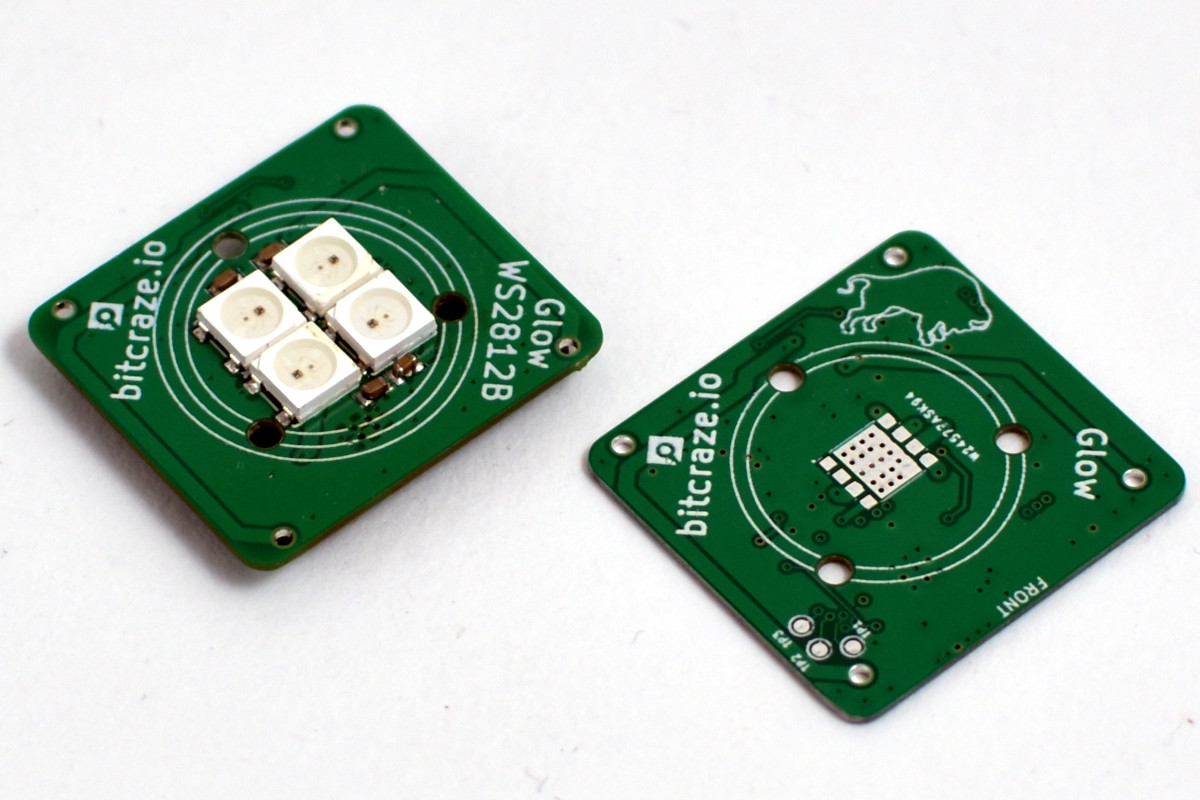
The Glow deck
I mentioned above that the idea was to be able to put charging on decks with other designs on them. To test out this concept I revived another old idea, the Glow deck! The Glow deck is a design where the LEDs are visible from the side and also a bit stronger. To achieve this a diffuse lens would be mounted on the PCB.
The first version of the Glow I made was years ago. It contained a high-power LED, which was really bright…and really warm. We stopped measuring the PCB temperature at 140 C, so that wasn’t something that was going to work out. It also only had one color and I wanted more.
This time around I decided to try two different versions. The reason for the two versions was that I wanted to see if more power actually added something (except complexity and price) when it came to visual effects while flying. One version uses 4xWS2812B LEDs (the same as on the LED-deck) while the other one uses a RGBW high-power LED. I quickly ran into the same problem as with the charging deck, mechanics. I wasn’t able to find a good size of a diffuse lens. Not wanting to be blocked by this I decided on designing one myself and printing it. Not sure how the size would affect the effect I designed two versions.
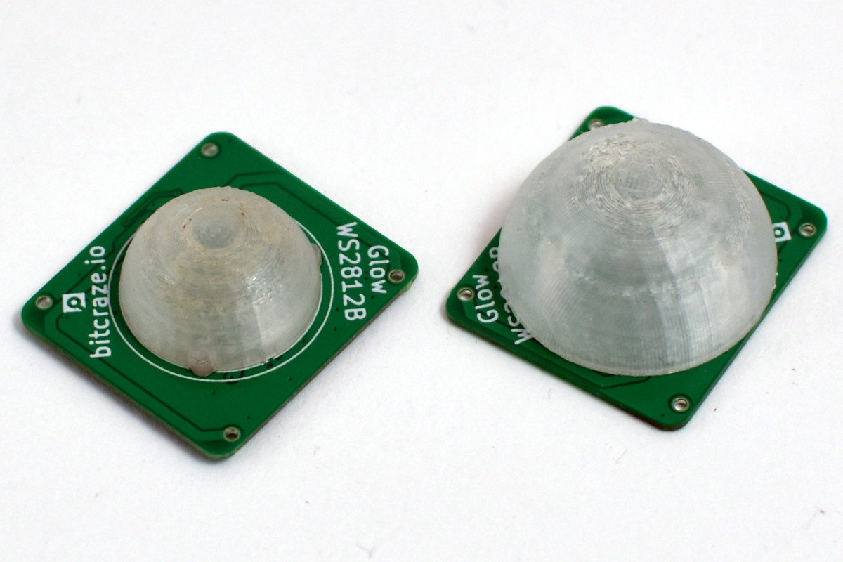
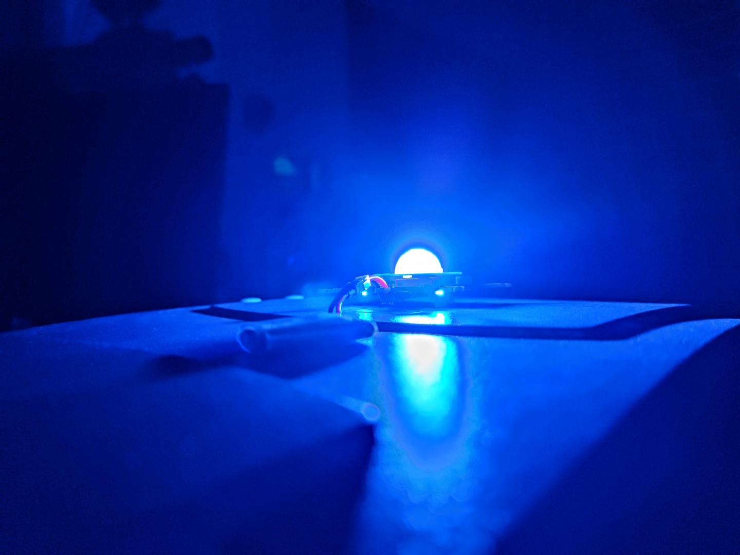
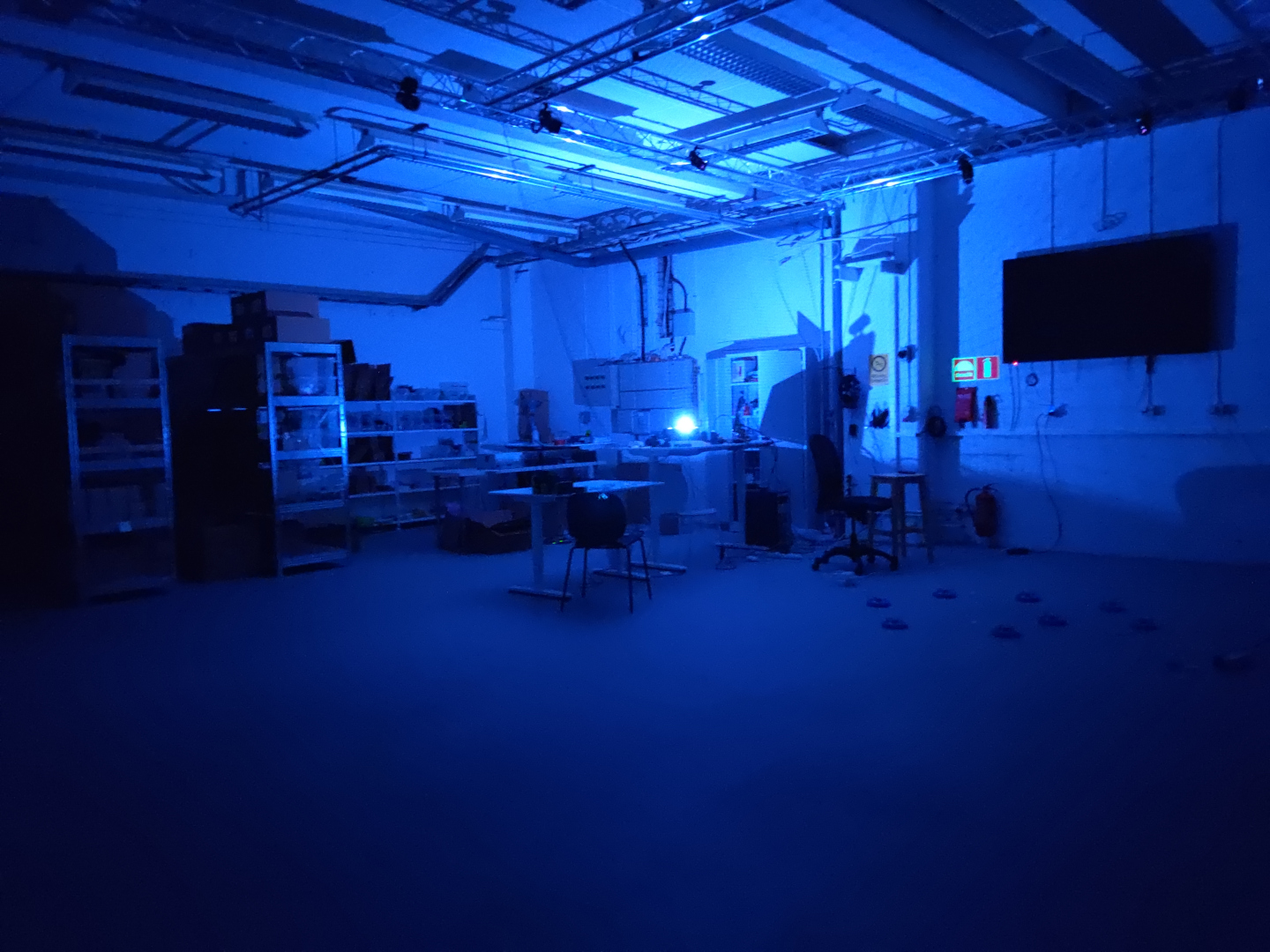
I haven’t had the time to try out the high-power LED version yet, but the results for the WS2812B version with the diffuse lens looks promising. It’s hard to see the effect in the images, but at least it shows that it’s possible to see the LED from the sides.
Conclusions
I think both the contact charging and the Glow looks promising and I’m happy with the results so far. But making one prototype is easy, making something that can be manufactured and properly sourced is different. If any of these ever turn into a product, the challenge will be finding the right pins, lens, charge base etc.
For the next step, I’m excited to see the high-power version of the Glow in action. This time around I’ve added proper dimming and temperature measurement :-) If you have any ideas, comments or questions drop a line below!