My name is Enya, and I am really excited to join the amazing team here at Bitcraze as an Application Engineer! In this role, I will get to work on a mix of fun things such as documentation, demos, usability, support and more, which is exactly the kind of variety that made me so drawn to this role.
I recently graduated with an M.Sc. in Engineering, focusing on information and communication technologies. During my education, I have specialized in interaction design and usability, which is also what I did my masters’ thesis in. While drones and robotics are still quite new to me, my background in software makes me eager to dive in and learn. The first time I came across Bitcraze I was fascinated by the technology, community, and the way this company works, and I knew right away that I wanted to be part of it. After all, getting the chance to explore the world of robotics feels like a dream opportunity for any engineer!
I’m looking forward to contributing, learning, and collaborating with all of you. Do you have ideas on how our documentation could be even more helpful? Or maybe a demo you’d love to see in action? I’d be happy to hear your thoughts!
Setting up a mobile indoor positioning system with the Crazyflie platform—specifically using the Loco Positioning System (LPS)—typically involves walking through a large room with a laser measure, sticky notes, and a bit of patience.
That was exactly my situation at work when setting up UWB anchors for mobile robot demonstrations, which often had to be relocated to different rooms. And it got me thinking—what if there were a more intuitive, flexible way to define and deploy these setups, especially in labs or educational settings where reconfigurability is key?
This question led to the development of XR-PALS, a mixed reality tool that simplifies the entire LPS configuration process. Instead of manually measuring anchor positions and inputting coordinates into cfclient, XR-PALS allows users to create and sync virtual and physical setups almost seamlessly—just by moving virtual anchors in space using a VR headset.
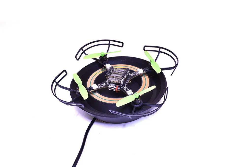
Three-step setup process for the Bitcraze Loco Positioning System, illustrating anchor connection, system configuration, and 3D Crazyflie drone tracking.
What is XR-PALS?
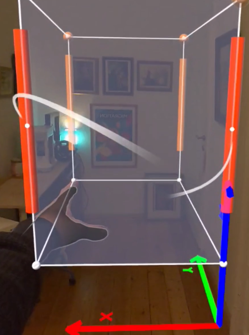
XR-PALS (XR-Powered Assistance for Loco Positioning Systems) is a tool we (Victor Victor and Dominik Grzelak) developed for defining cyber-physical spaces using UWB anchors on tripods. It runs on a passthrough VR headset (we used Meta Quest 3), allowing users to visualize the LPS layout and manipulate anchor placements in a virtual 3D environment until they are virtually and physically aligned.
Once everything is aligned, a single tap on the “Export” button sends the virtual anchor positions to a Rust-based middleware service running on a host machine within the same network as the VR headset.
It’s fast, visual, and eliminates the need for hand-measuring coordinates for our mobile robot demonstrators.
You can watch the system in action in our demo video:
Why We Built It
Usually, the LPS setup involves manual measurements and manual data entry in cfclient. This is time-consuming when environments change frequently—as is often the case in education and research.
With XR-PALS, the goals are to:
Speed up setup – Users in our study completed setups significantly faster.
Reduce error – Anchor placement is visual and interactive. No calculations needed.
How It Works
XR-PALS consists of two main components:
VR application Runs on a VR headset and displays the full anchor layout. Users can drag anchors, view distances, toggle info layers, and adjust alignment using natural hand gestures.
Middleware service A Rust-based REST API that basically bridges the VR app with the LPS anchors. This service receives the coordinates and remotely updates the LPS anchors—enabled by the open-source nature of the LPS firmware: bitcraze/lps-node-firmware. Coordinates are exported as YAML that can be imported by cfclient.
System architecture.
User interactions.
Real-World Evaluation
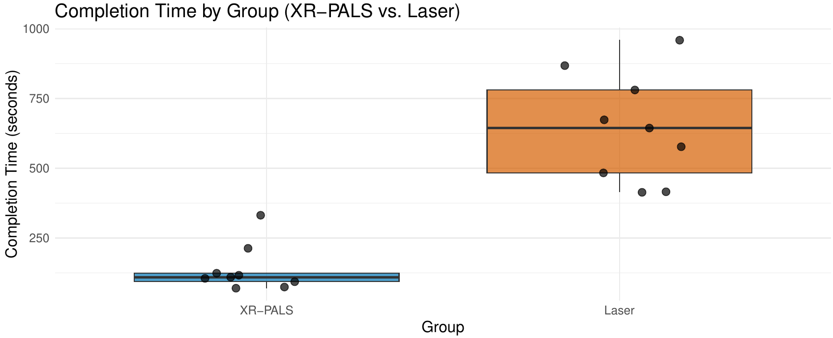
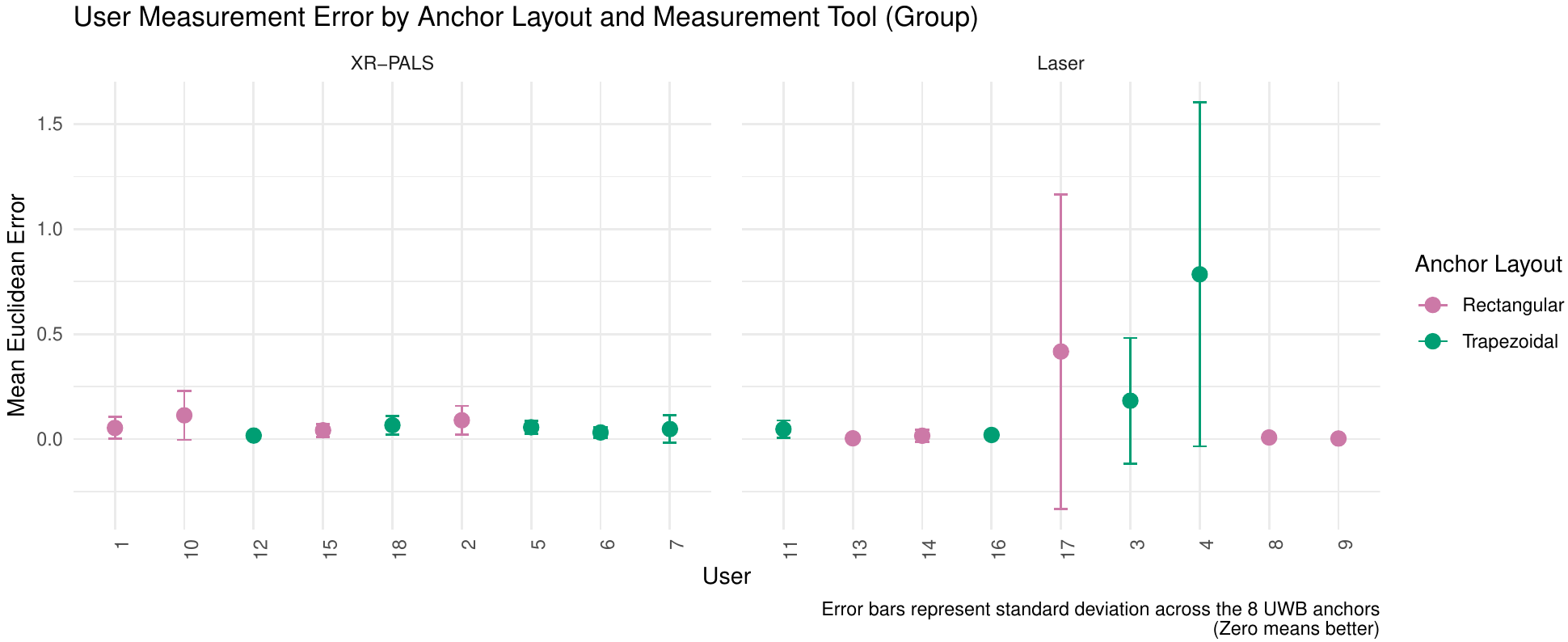
We compared XR-PALS against a traditional laser measurement tool in a user study involving 18 participants from our Faculty of Computer Science. Each participant had to configure a LPS layout (trapezoidal or rectangular) using one of the two tools.
Results:
XR-PALS users completed the task faster
Fewer measurement errors
Higher usability scores and confidence
Lower cognitive load, especially for the trapezoidal layout
Bar chart comparing task completion times between XR-PALS and laser.Lower values are better.
Measurement error comparison between XR-PALS and Laser. Lower values are better.
The minimal loss in accuracy compared to the time saved is not dramatic for our use cases, compared to the time saved—especially when more participants were able to correctly determine the coordinates overall. In general, users were more confident using VR glasses than a laser measurement device.
Summary and What’s Next
So if you’re working with dynamic robot setups or swarm experiments, XR-PALS might save you a lot of setup time.
The app works natively with the Bitcraze Loco Positioning System and, so to speak, extends the capabilities of the cfclient.
Here’s what we’re currently thinking about:
Supporting larger anchor sets within the app (currently limited to 8 anchors)
Improving user interactions based on feedback from our user study
Displaying anchor diagnostics (e.g., latency, power levels)
Simpler layout reusability (layouts can be saved and shared only via the computer)
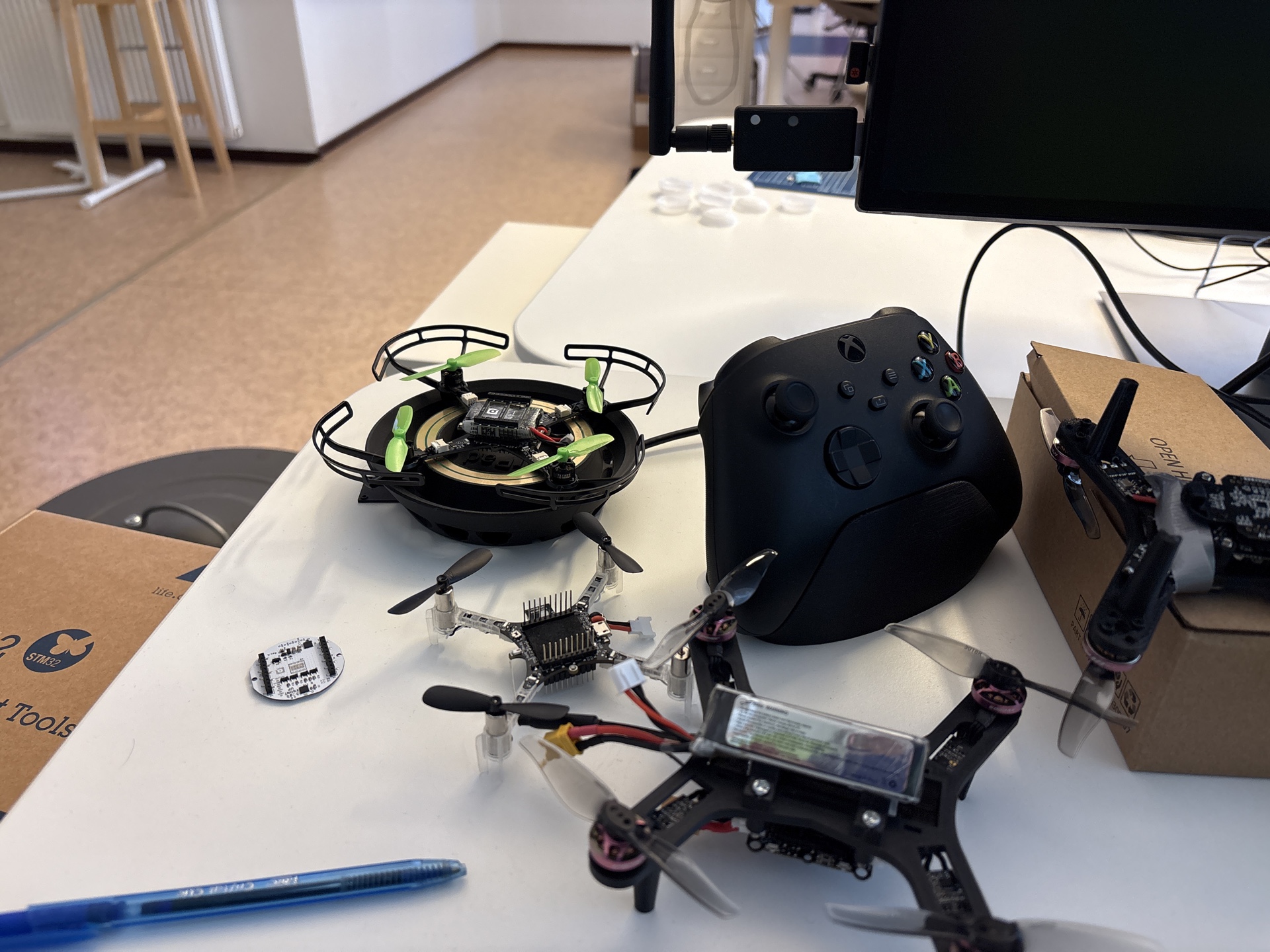
At the beginning of the year, we released the Crazyflie 2.1 Brushless charging dock. This project was very much an experiment for us since this is the first product we are mainly manufacturing and assembling by ourselves in Sweden. We though we would write a little bit about the reason we made it that way and how it is going.
The Chaging dock is already described in a brunch of peviousblock post. It is basically a landing pad for the Crazyflie Brushless that charges the Crazyflie when landed. This is an idea and a design we have been using for years for our fair demos and that has been very useful, we would not be able to continuously fly at fair without it! Some of us even started using is on their desk to keep their Crazyflie Brushless fully charged at all time while developing with it:
However, even though it has been so useful for us, and we designed the Crazyflie Brushless to be compatible with contact-charging, we where not sure of how many people out there would want or need such a charging dock. So we decided to make it available in an experimental manner by manufacturing it by ourselves!
Why ‘made in Malmö’?
While the manufacturing we have in place for all our other products works really well, it requires a non-trivial amount of effort to start the first manufacturing batch. This is mainly due to the fact that the full mass production chain needs to be setup for the first batch and that production happens outside Bitcraze, this requires a lot of work in documentation, planning and administration.
However by doing the production in house, we are able to fix issues as they arises and to work in a much more agile way. In house production will of course no scale, but for a proof of concept it might work, this is at least what we wanted to experiment with.
There are two main improvements that has allowed us to even consider in-house experimental production: the advent of cheap and efficient PCBA services and the improvement in 3D printers reliability. This allows us to source all the parts and assemble them to make the final product.
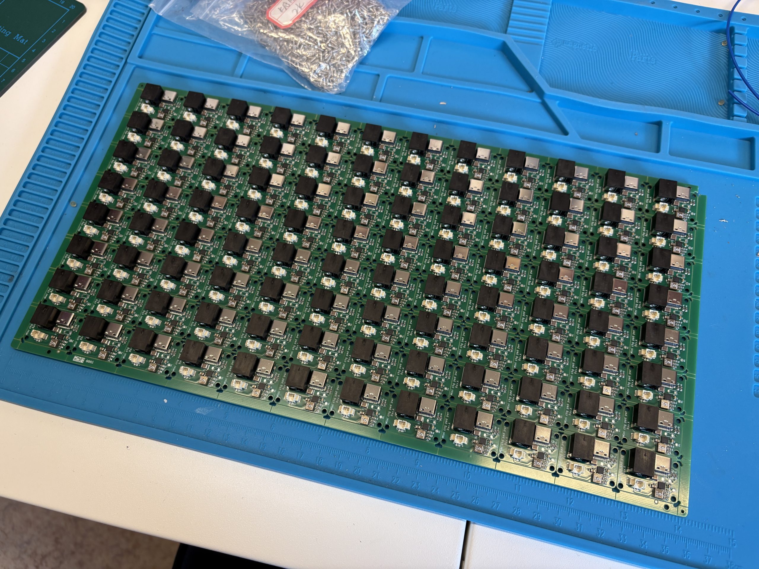
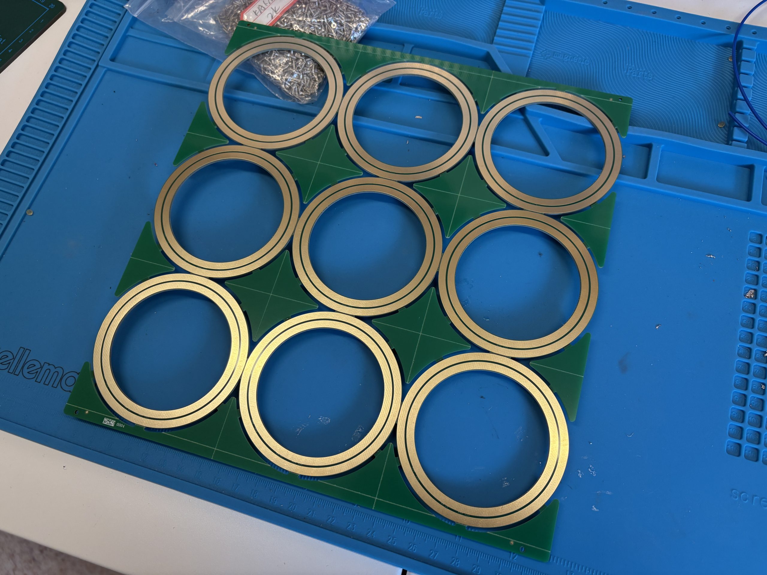
How is a Charging Dock made?
The charging dock is comprised of two main parts: the plastic landing pad and the electronic.
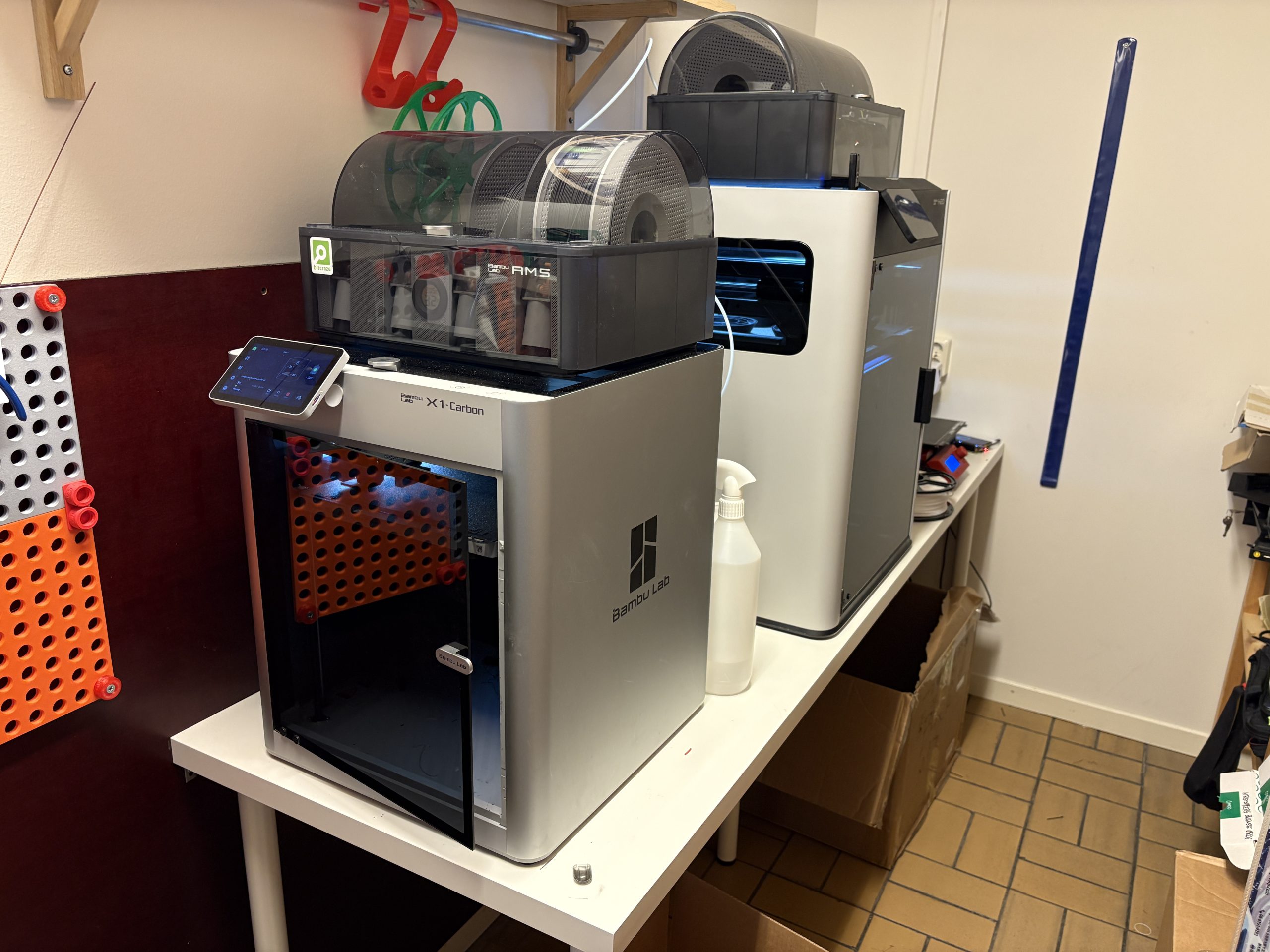
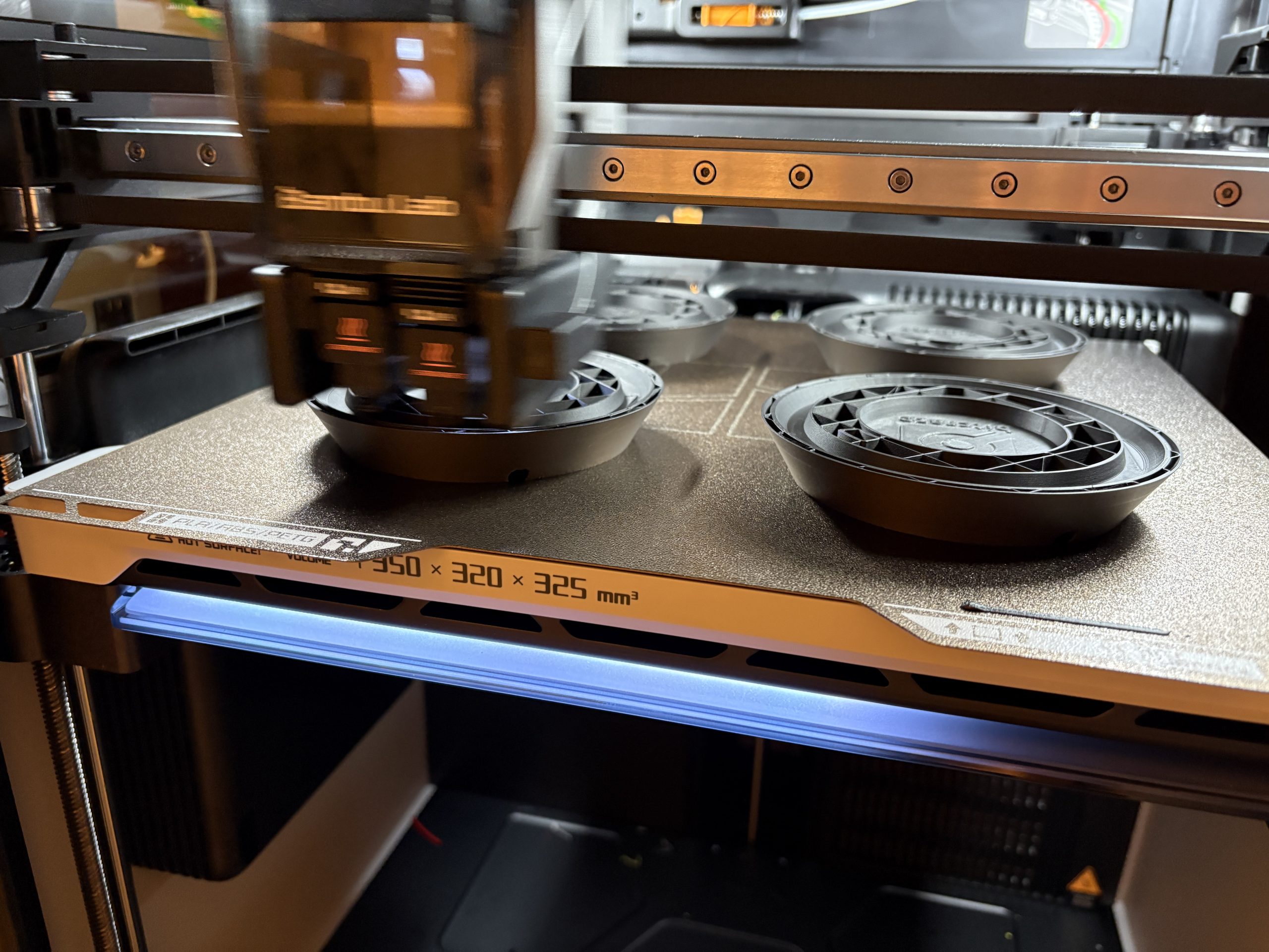
The Landing pad is 3D printed by us. We now have a mini-print-farm at the office (if a Swarm starts at 2 drones, a print farm shall start at 2 concurrently running printer :):
What made it possible for us to consider running this kind of production was when we got our Bambulab X1 carbon. It is much more reliable and most importantly easier to maintain that any printer we got before, which gave confidence that we could start making products of what we printed. We now have an H2D as well. This currently allows us to print 12 landing docks per working day.
On the electronic side, we are now able to order fully assembled PCB, and even custom cable within weeks.
All we then need is assembly and testing and we got ourselves a small production line with very little risk and a lot of flexibility.
What now?
We are very pleased with what we have achieved so far with the charging dock. The first batch is sold out and we have started manufacturing a new batch with no big pain-point in sight. At some point we will have some decision to take though: do we continue in house or transition to more traditional manufacturing? Will all the work we put so far be useful for setting up mass manufacturing or will we have to restart from zero? At what batch size or frequency will we need to transition?
However this is also one of the great advantage of this: we have full control and we can decide when to manufacture where. As we have talked a bit previously, Bitcraze is a self-organized company, and this experiment actually fits very well with our way of working and keeps us agile. We hope this can free us from the doubts we usually have when thinking about more ‘niche’ products and will allow us to try new things in the future.
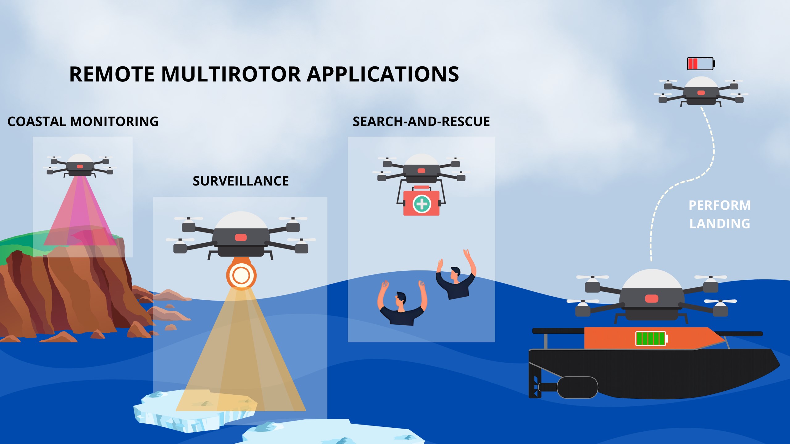
Unmanned aerial vehicles (UAV) are invaluable to challenging remote applications, including coastal monitoring, surveillance for safe passage in icy waterways, and search-and-rescue missions. However, after deployment in a remote setting, the functional life of the multirotor is ultimately limited by its battery life. The research we continue to investigate is the ability to cooperatively and autonomously land a multirotor on an uncrewed surface vessel (USV) for recharging. We address this problem in real time with safe control algorithms that we apply on a Crazyflie.
Approach
Our approach enables the Crazyflie to cooperatively coordinate, with a simulated USV, a safe landing in severe wave conditions. It is critical to the autonomy of the system that the agents do not know when or where they’re going to land at the outset, they are cooperating in real time to make these determinations. The novelty of this work is three primary contributions:
Learning a Spatial-Temporal Wave Model as a Gaussian Process
We first learn the local tilt model, representative of the spatial and temporal impact of waves on the tilt angle of a USV, using Gaussian Process (GP) regression. Prior to the execution of the landing, the USV collects Nd noisy observations D = {q, t, φ²}, where q is the position of the USV, t is time, and φ is the tilt angle of the USV. We use GP regression to learn the spatial-temporal tilt model: fw(q, t) = (φ(q, t))² . The predicted tilt and uncertainty, conditioned on the observed data D, at a query point a = [q, t] can be inferred using the posterior distribution.
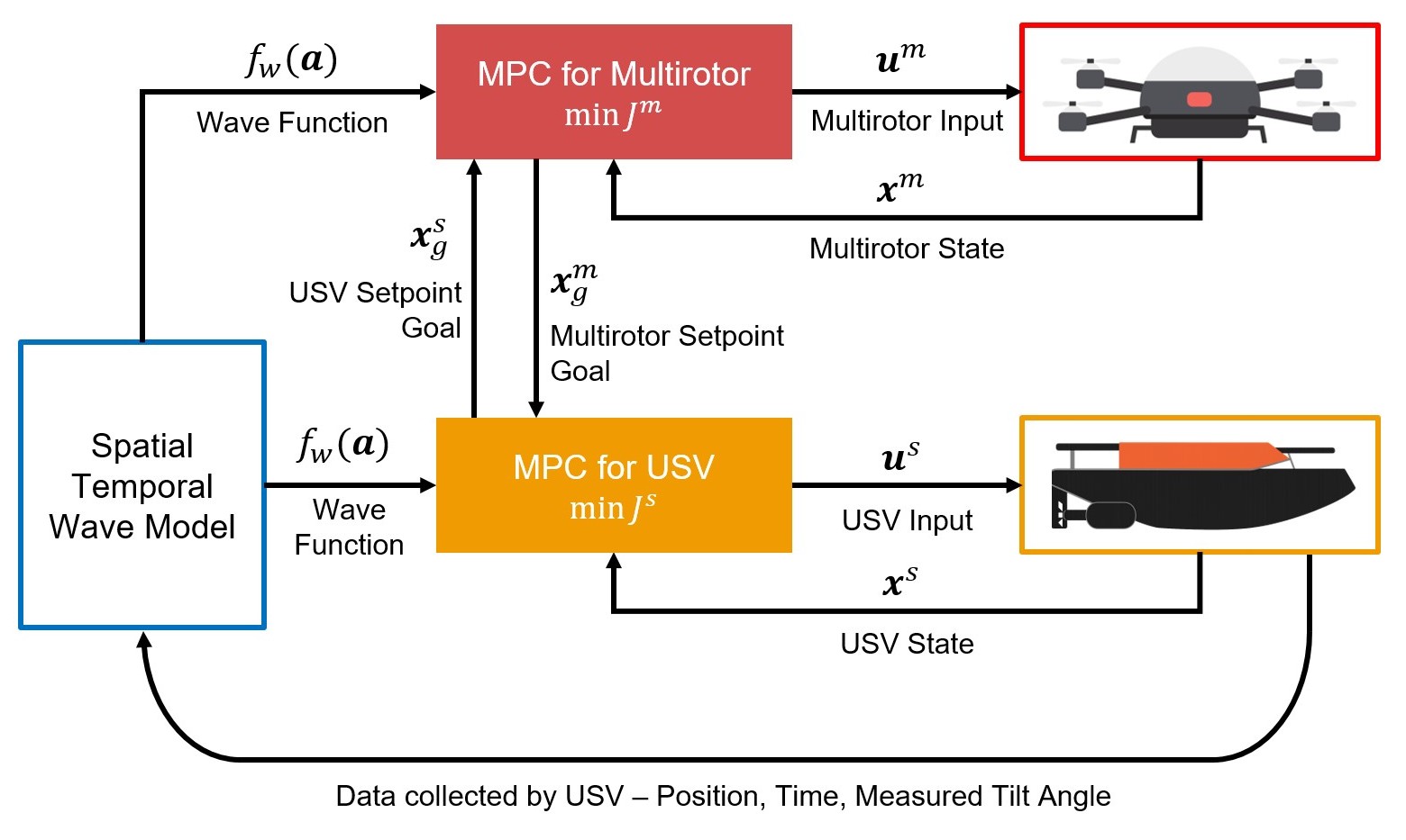
Distributed Model Predictive Control
Our proposed model predictive control (MPC) architecture combines standard tracking MPCs for the Crazyflie and USV and augments them with additional artificial goal locations. These artificial goals enable the vehicles to coordinate without prior guidance. Each vehicle solves an individual optimization problem for both the artificial goal and an input that tracks it but only communicates the former to the other vehicle. The MPC integrates, into the cost functions for both vehicles, the learned mean and uncertainty quantification of the spatial-temporal wave model from the GP regression. This encourages the agents to converge to calmer waters enabling safer landings in variable wave conditions.
Low-Cost USV Simulation Testbed Platform
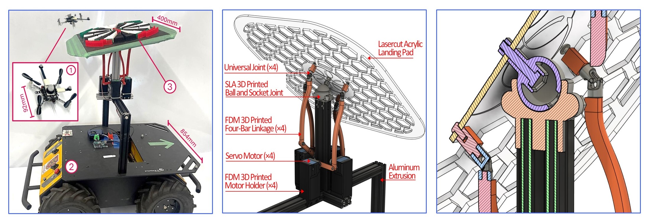
To validate the proposed MPC scheme for landing on a USV, we simulate the spatial-temporal motion of a USV in waves of variable intensity using a custom tilting platform. The custom tilting platform has two degrees of freedom (roll, pitch) and is affixed to the deck of a differential-drive unmanned ground vehicle (UGV), the ClearPath Robotics Husky. We selected a differential-drive UGV to replicate the motion of a broad range of USVs, including those with differential drive and conventional rudder steering. Our platform is low-cost, modular, and open source, enabling rapid testing and benchmarking of UAV-USV landing strategies indoors before going onto the water which is high-risk and expensive.
Block diagram of our proposed distributed model predictive control scheme.
Overview of the USV simulation testbed tilting platform for ground vehicles. Left: the platform is shown mounted on the deck of the ClearPath Robotics Husky with the Crazyflie 2.1 hovering above. Center: a closer view of the landing pad configuration and platform components. Right: Section view showing the ball-and-socket joint and the linkage mechanism.
Experimental Setup
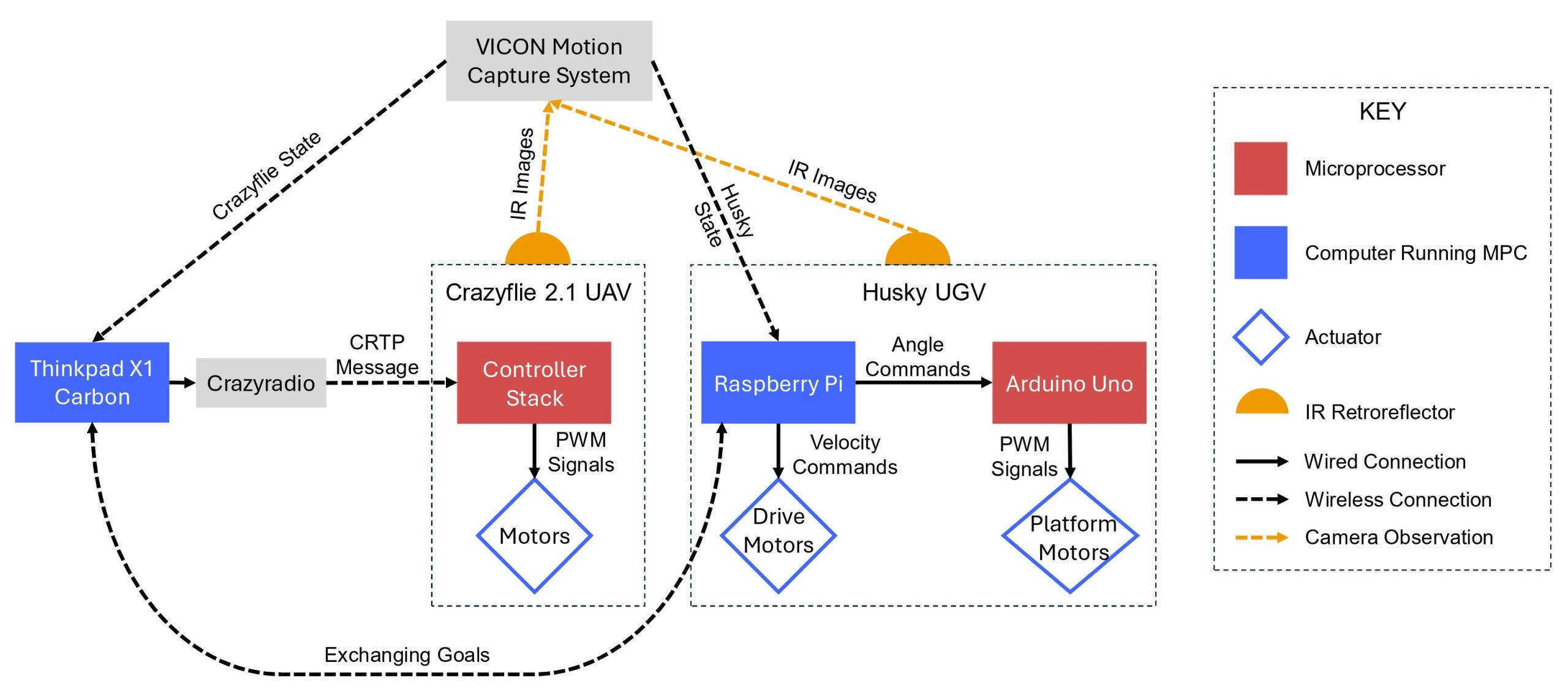
Full system architecture.
We evaluate the proposed MPC scheme for UAV-USV cooperative landing in indoor experiments using the Crazyflie 2.1 and our tilting platform. These experiments represent a scaled-down version of real-world harsh wave conditions. Amplitude and frequency are informed by a survey of waves along the coastlines of the Great Lakes of North America. We select a spatially decaying sine wave whose amplitude decreases gradually with increasing x-position. We expect the Crazyflie and the simulated USV to cooperatively select the safest landing spatially and temporally by learning the GP and incorporating it the MPC scheme.
The UAV MPC is run off-board on a Thinkpad X1 Carbon with Intel Core i7-1270P Processor. The MPC runs at a frequency of 50Hz and transmits control inputs to the Crazyflie via long range Crazyradio USB. The Raspberry Pi onboard the Husky runs its MPC at 10Hz. The two vehicles communicate their goals using ROS topics on a local WiFi network and receive their own pose feedback at 240 Hz from a VICON motion capture system.
Experimental Results
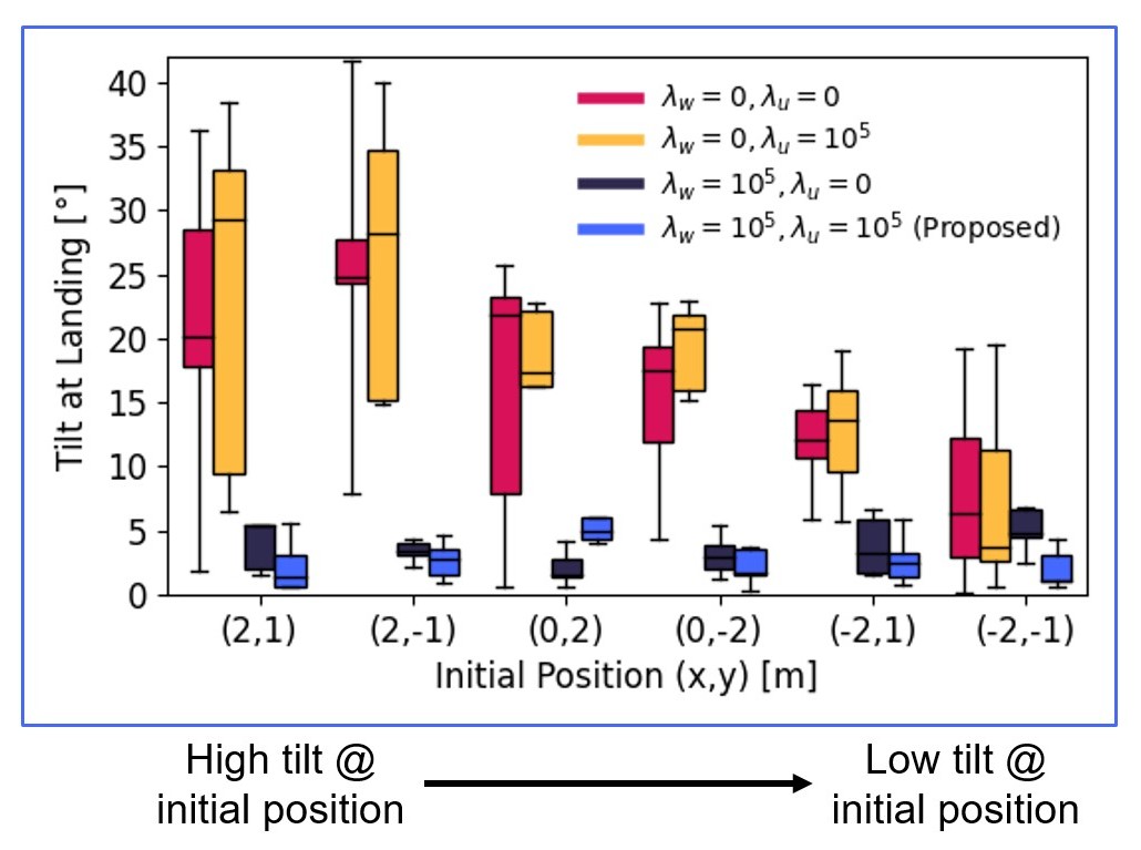
Experiment 1. We define the tilt model. Our proposed distributed MPC scheme can locate a low-tilt landing location from all six initial platform positions.
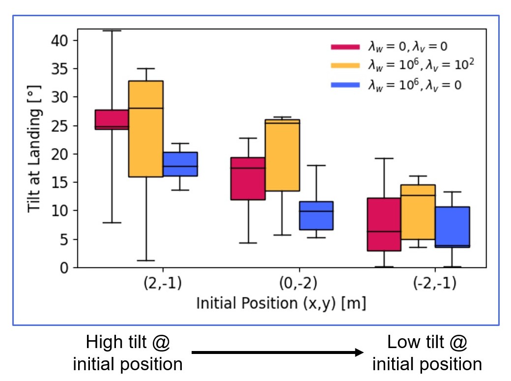
Experiment 2. We learn the wave model using a GP. The MPC scheme can locate a low-tilt landing location from all three initial platform positions.
In the first set of experiments, we assume no uncertainty in the tilt model. We compare four MPC weighting strategies ranging from a purely cooperative strategy in red (where neither vehicle weights wave tilt in the MPC, neglecting spatial-temporal tilt motion), to our proposed strategy in blue (where both vehicles weight wave tilt highly in the MPC). In this set of experiments, our proposed approach (blue) reduces the tilt angle of the platform at landing by between 68-89% and results in a 53% increase in landing success rate over the purely cooperative strategy (red).
In the second set of experiments, we learn the wave tilt model as a GP. We compare the purely cooperative strategy in red from before to our proposed strategy in blue where we weight the posterior mean cost from the GP regression. In this set of experiments, our proposed approach (blue) reduces tilt angle of the platform at landing by 23-32% and results in a 47% increase in the landing success rate over pure cooperation (red).
Future Work
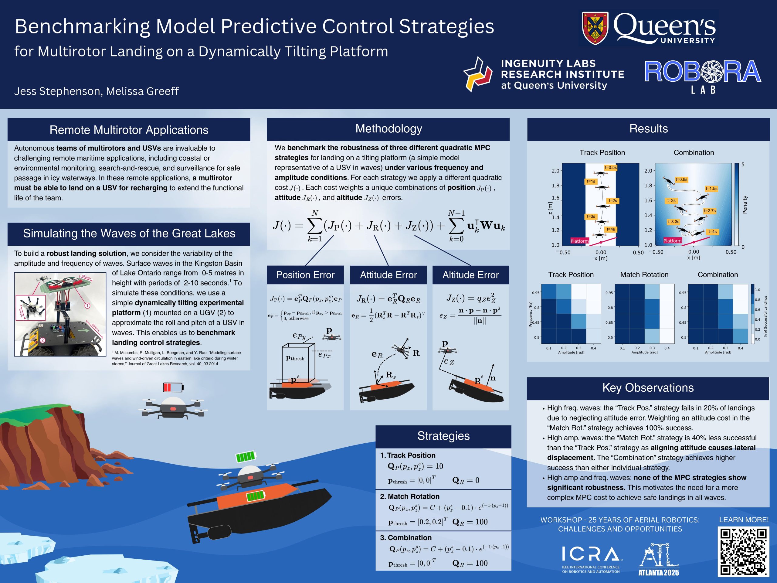
In the work presented above we assume that there is a local region with calm waves that can be reached by both vehicles to then perform a safe landing. However, in practical scenarios, spatial-temporal assumptions are not realistic if an emergency landing is necessary or if time and resources are constrained. Recently, we explored quadratic MPC strategies for landing a Crazyflie on the tilting platform in high frequency high amplitude conditions. In these strategies we include optimization costs that weigh position, attitude, and altitude errors between the multirotor and the platform.
Though all strategies successfully land in low-frequency, low-amplitude conditions, they have low success in the higher-amplitude conditions. Therefore, designing a safe controller that is robust to a wide range of wave amplitudes and frequencies is an ongoing research area.
Poster presented at the workshop ’25 Years of Aerial Robotics: Challenges and Opportunities’ at ICRA 2025.