Finally here is the last, and probably most interesting part of the “Measuring propeller RPM” series, see part 1 and part 2 to catch up. Now it is time to gather some data and display what we get.
As described in part 2 we are now able to measure each propeller RPM with the expansion board we made and with the code we added. This can, as been described in part 2, be logged to a csv file using the cfclient. Next thing would be to do something useful with it. To do that we use Octave (very similar to Matlab but open source). The first thing that could be interesting to know is the step response for a motor and propeller. This was acquired by altering the Crazyflie 2.0 firmware a bit to do a step from zero to max trust and then to zero again. It was done on M1 with a fully charged battery.
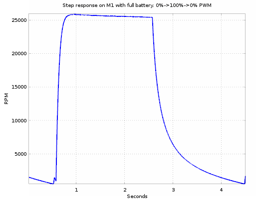
The motor goes from zero to 25k rpm in about 180ms, quite impressive. What is also interesting is that the falling slope in the range 15k to 20k rpm is quite similar to the rising slope in the same region. The inertia of the turning parts of the motor and the propeller is quite low so this energy will quickly be consumed when the motor and propeller starts to coast. This is good as it will lead to better maneuverability.
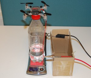 Knowing the RPM is great but it is the thrust that is most interesting. So to get this we need a rig where we can measure it. We made one out of a bottle to which we glued a prototype board on that we put on a scale, not a perfect rig but simple and probably good enough. Then we made a program that ramped up the PWM from 0% to 93.75% in 16 steps with stabilization disabled. We also connected the Crazyflie 2.0 to a power box where we could measure the current. The program would increase the thrust in 16 steps and during each step we took a reading of the thrust and current. The RPM, voltage and PWM was logged over the cfclient at the same time. Some manual work was needed afterwards to correlate the data and get it into a table. While in the table a lot of interesting plots could be graphed.
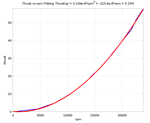 The first one would be the rpm and thrust as this transfer function is interesting. By using the Octave polyfit function the second order fit could be found. It is a pretty accurate fit and with this fit it is easier to get the thrust, as the rpm is the only variable needed, which is easier to measure. The fitting function returned by polyfit is:
Thrust (in gram) = 1.0942e-07*rpm² – 2.1059e-04*rpm + 0.15417.
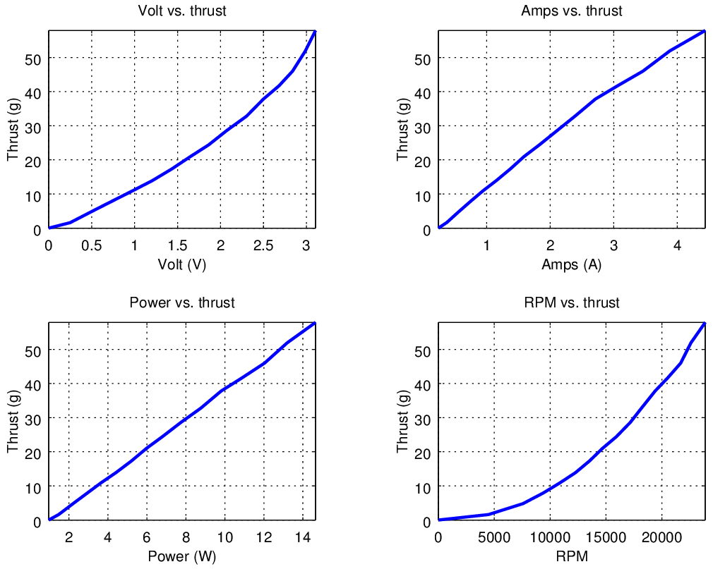
Here is a combined plot of some other interesting parameters. Notice that the voltage graph is ~quadratic, the current ~square-root and the power linear. From the power graph one can find out that the thrust efficiency is about 3.8 gram/W. Not super good but pretty good for a quad of the Crazyflie 2.0 size.
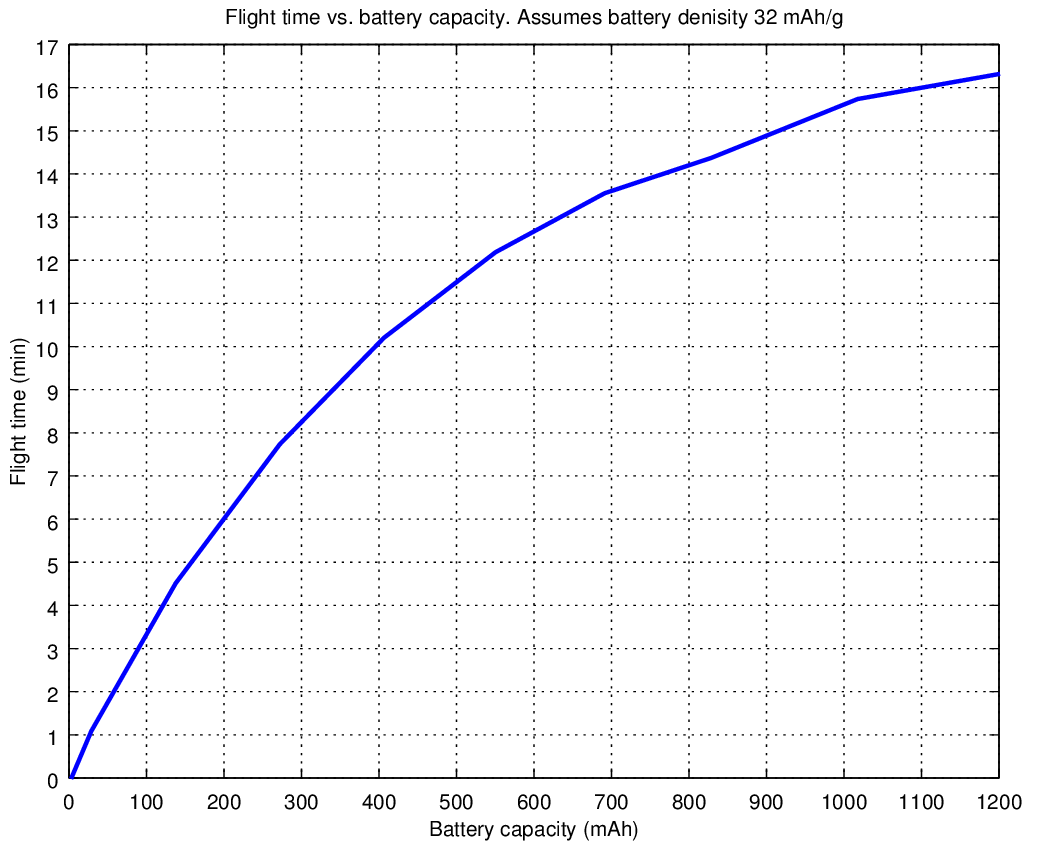
Another interesting graph is the graph of the flight time. Since we know the power consumption and the battery characteristics we can plot a graph of an estimated flight time depending on the battery size. This graph makes the assumption the battery capacity per weight is 32mAh/g.
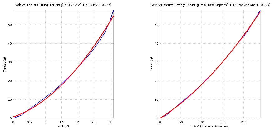
And finally the transfer function we set out to find, the PWM to thrust. The problem with this is that motors are controlled by voltage (PWM) and the voltage comes from the battery, which varies with the power taken from the battery due to internal resistance. Therefor we made two fitting functions, one based on measured battery voltage while applying PWM, and one based on the PWM. Looking at the graph one interesting thing is that the polyfit is making a better fit (red curve) for the PWM. I would have expected the opposite. Something that we will have to investigate further. Or maybe one of our readers have the answer?
On the wiki we will update this analysis with some more details and the raw data so if you are interested please have a look! Hopefully using this information we can make the Crazyflie 2.0 fly even better.
On the news side there is a new version of the Android client available on Google play, thanks Fred! Also Fred has uploaded the slides of his Crazyflie lightning talk at Fosdem 2015.
As a rough guess, the measured voltage will depend quite a bit on the momentary load on the battery, and that dependency will likely change depending on the base voltage. So I’d expect to see more variation in that measurement than in the more direct (and more exact) PWM value.
We should probably do a test where we directly apply power to the motors. Not going through the Crazyflie battery->power lines->mosfet to get those parameters out of the way.
So, how you think, there is possible now to realize vertical motion ( move up, landing down, altitude hold ) using measurement of rpm and thrust without using poor altimeter?
These measurement could actually be used to help the pressure sensor. Better knowing the propeller properties might help getting an idea of the vertical rate and improving the altitude control algorithm, but the pressure sensor is still the only sensor capable of giving an absolute measurement (and the pressure sensor in itself is actually quite good, it is the pressure in a room that fluctuates too much and that we have to compensate for ;).
A little late to the game here, but thrust is actually calculated from the square of the prop rpm, so you could get a real clean curve just using that. Using your data, I found T = 9.919*10^-8 * (rpm)^2 gives good data :)
Simpler is often better! Do you have a sensor to measure the rpm or maybe you are using a brushless ESC?
Hi! I conducted an experiment to measure PWM to Thrust as outlined in your document (see link).
https://github.com/orgs/bitcraze/discussions/1337
However, even though the PWM was enough to achieve hovering, the weight of the Crazyflie, which is 27g, wasn’t measured at all. What could be the issue with my experimental method?