Early on when we started to work on the Loco Positioning system, we came up with an idea of a Crazyflie autonomously flying into a light box, positioning it self for a few product pictures and then flying out again. The positioning system is now pretty mature and close to leave Early Access and this Friday we finally got around to do it. In this blog post we will share what we did and it also doubles as a brief howto on how to set up the system and fly a simple autonomous sequence.
We used a Crazyflie with a Loco Positioning Deck and eight Loco Positioning Anchors in our setup. Six anchors would have been fine too, but we happened to have eight in our flight lab.
When working with the Loco Positioning system the first step is always to make sure the anchors are set up correctly. We had an experimental version of the anchor firmware so we started out by pulling down the latest stock version of the source code and compiled it into a .dfu file. After that we fired up the brand new lps-tool that is used to flash firmware and configure the anchors. The anchors must be connected with a USB cable to the computer but the lps-tool reduces the flashing and configuration into a few clicks. When all anchors were updated we were ready for the next step.
The positions of the anchors are stored in the anchors them selves and the position is transmitted to the Crazyflie as a part of the ultra wide band messages used for measuring the ranges to the anchors. This way, the Crazyflie gets both anchor positions and ranges in the same process and has all the information needed to calculate its position. The second step is thus to store the positions in the anchors. In our “flight lab” we have fixed mounts for the anchors with known positions, so we could skip measuring the physical positions of the anchors.
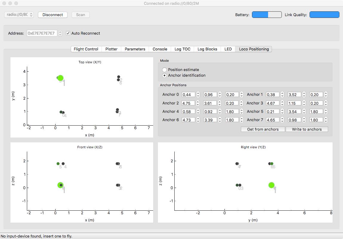
We are working on making it possible to remotely configure the anchors to reduce the need to physically connect to them, and the position can now be set from the Crazyflie Client. We simply opened the “Loco Positioning” tab in the client, connected to a Crazyflie (with a Loco Positioning deck mounted), entered the anchor positions and hit the “Write to anchors” button. A few seconds later the anchor positions in the graphs were updated to indicate that the positions have been written to the anchors and then subsequently sent back through the ultra wide band messages to the Crazyflie.
Step three is to verify that the system is working as expected. First thing is to check that we did not mix the anchors up when configuring or placing them. In the “Loco Position” tab in the client, click the “Anchor Identification” button. In this mode anchors are lit up in the graphs when the Crazyflie gets close to them in the physical world. We went from anchor to anchor with the Crazyflie and checked that the correct anchor lit up on the screen. When confident that all was good we changed to “Position estimate” mode and verified that the estimated position matches the physical position of the Crazyflie. We have found that it can be very hard to understand, for instance that two anchors have been mixed up, by looking at the estimated position and that the “Anchor Identification” step simplifies the setup.
At this point we had a fully functioning Loco Positioning system ready for autonomous flight!
Now it was time to script a sequence. The easiest way to script a sequence is to start from the autonomousSequence.py example. Our intern Alfred took over at this point, he updated the uri to the correct settings and crafted a sequence to take off, fly into the light box, wait a while and then fly back out for a stylish landing in his hand!
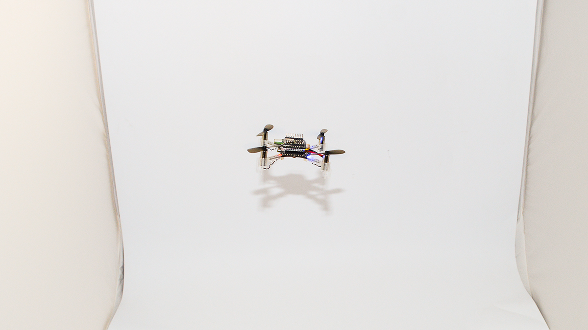
Now we were ready for the actual photo shoot and Björn came down with the camera to shoot the product pictures. We hope you enjoy the results!