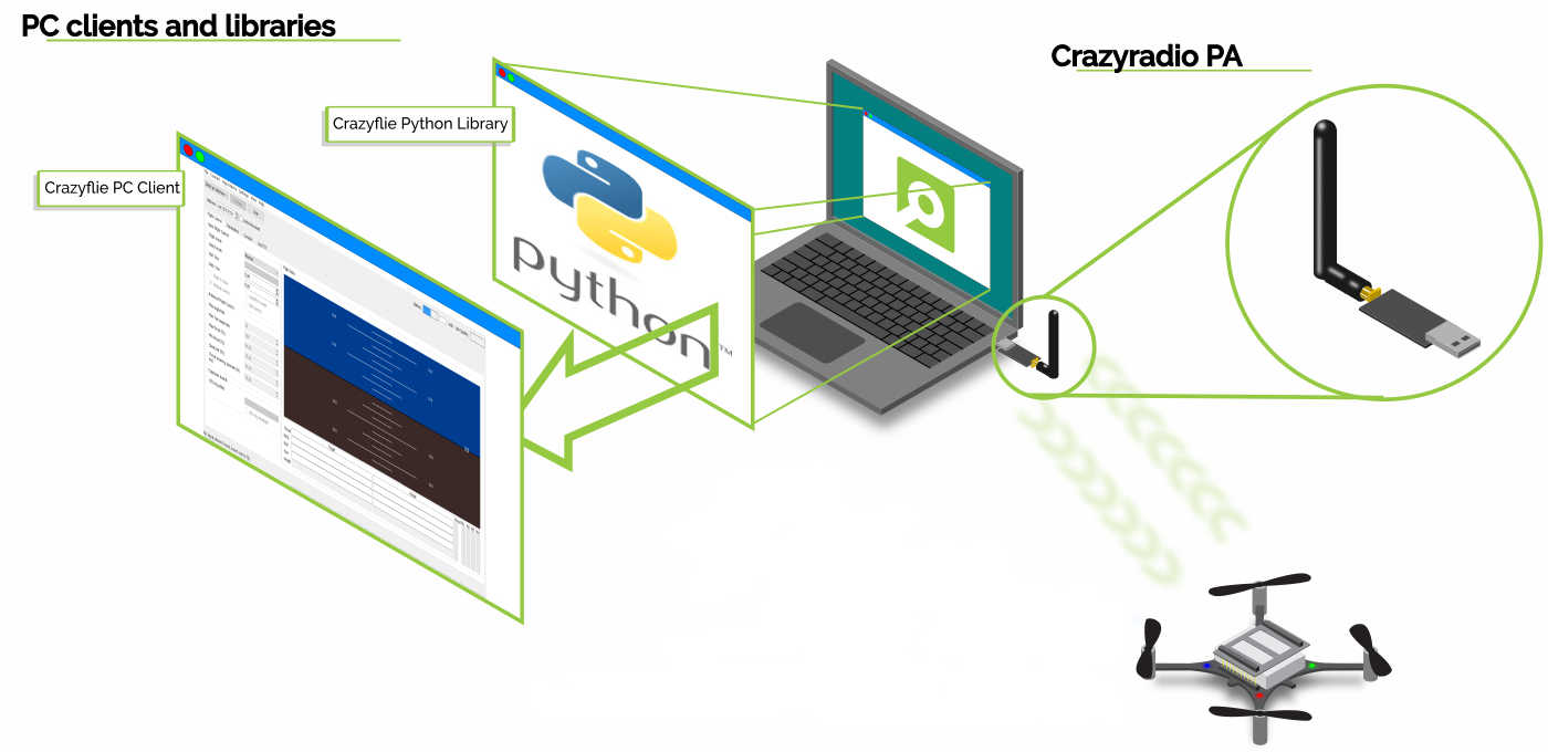
A common task with the Crazyflie is to add a new controller or estimator. As we get some questions on how to do this, we will outline the process in this post. We will show how to add a custom controller and estimator that runs in the Crazyflie, built as an out-of-tree build.
This post assumes some basic knowledge about the Crazyflie firmware, the C programming language, how to build the firmware and flash it to a Crazyflie. If you need some more information on these topics, please see the “Getting started with development” tutorial. For an overview of how estimators and controllers are used by the stabilizer module, please see the firmware documentation.
Overview
The Crazyflie firmware is designed to make it easy to add custom controllers and estimators, a plugin system keeps the code clean and well separated. We will look at the details later, but the basic principle is to first write your new controller or estimator and then register it in the firmware. When the code has been compiled and flashed to the Crazyflie, the new module is activated by setting a parameter from the client or a python script.
We will implement the example as an app, which is a great way to make sure you can upgrade the underlying firmware without messing up your code. An app is a piece of code that exists somewhere in you file system outside of the main firmware source code. This setup minimizes the dependencies and the main firmware source tree can be upgraded without affecting your app (in most cases). That means there is no need for merges or complex management of source trees.
Registration of modules
Let’s first look at how controllers and estimators are registered and called in the plugin framework. We will use the controllers to show how it works, but the estimators are implemented in a similar way and it should be easy to understand how it works.
Note that there has been some updates of the Crazyflie firmware source code lately and any reference to the source code will be to the latest version (as of today).
The starting point of the controller implementation can be found in the src/modules/src/controller.c file, here we can find an array called controllerFunctions that holds a list of all the controllers in the system.
static ControllerFcns controllerFunctions[] = {
  {.init = 0, .test = 0, .update = 0, .name = "None"}, // Any
  {.init = controllerPidInit, .test = controllerPidTest, .update = controllerPid, .name = "PID"},
  {.init = controllerMellingerFirmwareInit, .test = controllerMellingerFirmwareTest, .update = controllerMellingerFirmware, .name = "Mellinger"},
  {.init = controllerINDIInit, .test = controllerINDITest, .update = controllerINDI, .name = "INDI"},
  {.init = controllerBrescianiniInit, .test = controllerBrescianiniTest, .update = controllerBrescianini, .name = "Brescianini"},
  #ifdef CONFIG_CONTROLLER_OOT
  {.init = controllerOutOfTreeInit, .test = controllerOutOfTreeTest, .update = controllerOutOfTree, .name = "OutOfTree"},
  #endif
};Code language: PHP (php)
We can see that there is currently four controllers in the list: the PID controller, the Mellinger controller, the INDI controller and finally the Brescianini controller. There is also an “empty” controller at the top that is not important in this context and we will simply ignore it. At the bottom we find the out-of-tree controller, we will discuss this later.
Each controller must implement three functions: an initialization function, a test function and a controller function that performs the actual controller work. Signatures for the three functions are defined in controller.c. The functions are added to the list as function pointers that can be called by the stabilizer when needed.
There is a parameter, stabilizer.controller, in the stabilizer that tells the system which controller to use in the stabilizer loop. This parameter simply contains the index in the controllerFunctions list that will be used. For example, the default value 1 will make the stabilizer loop call the controllerPid function every iteration. If the value of the stabilizer.controller parameter is changed, the initialization function for the new controller will be called and subsequent calls from the stabilizer loop will be done to the new controller function.
We will not go into details of how to implement the actual controller here, but the existing controllers can be used as examples.
There is a similar list/implementation for estimators that can be found in src/modules/src/estimator.c.
Adding a new controller
Suppose you want to add a new controller. It would be possible to add a new file in the Crazyflie firmware with your new controller implementation, add the function pointers to the list in controller.c and that would work just fine. The problem with such implementation would be that it is hard to maintain, your new files would be mixed with the files in the main firmware file tree, and even worse, you would have to modify the controller.c file to add your controller. The next time there is a new awesome feature in the firmware source code and you want to upgrade to the latest version, you will run into problems as you have to handle the files you modified!
A better solution is to use an app instead as apps are built out-of-tree, that is not in the main source tree. This removes the problem of merging changes in the main source files, all you have to do is to pull in the new file tree and recompile.
But how to register your new controller in the controller list? This is what the last line in the list of controllers is for
// ...
#ifdef CONFIG_CONTROLLER_OOT
  {.init = controllerOutOfTreeInit, .test = controllerOutOfTreeTest, .update = controllerOutOfTree, .name = "OutOfTree"},
#endif
// ...Code language: PHP (php)
If CONFIG_CONTROLLER_OOT is defined we add a controller with the three functions controllerOutOfTreeInit, controllerOutOfTreeTest and controllerOutOfTree. All you have to do in your app is to define CONFIG_CONTROLLER_OOT and make sure the functions in your controller are named like above. That’s it!
Example implementation
Now we will create a new app and add a new controller, step by step. We assume that you have a newly cloned firmware repository in your filesystem to work on.
We will show the linux flavor of commands, but it should be easy to convert to other platforms.
Create a new app
The easiest way is to start from an existing app to get started, let’s use the hello world app. Copy the app and move into the new directory
cp -r examples/app_hello_world examples/my_controller
cd examples/my_controller/
Let’s rename hello_world.c
mv src/hello_world.c src/my_controller.cWe have to tell kbuild that we renamed the file. Open src/Kbuild in your favorite editor and update it to
obj-y += my_controller.oNow let’s fix the basics in my_controller.c, open it in your editor and change according to the comments bellow:
#include <string.h>
#include <stdint.h>
#include <stdbool.h>

#include "app.h"

#include "FreeRTOS.h"
#include "task.h"

// Edit the debug name to get nice debug prints
#define DEBUG_MODULE "MYCONTROLLER"
#include "debug.h"


// We still need an appMain() function, but we will not really use it. Just let it quietly sleep.
void appMain() {
  DEBUG_PRINT("Waiting for activation ...\n");

  while(1) {
    vTaskDelay(M2T(2000));

    // Remove the DEBUG_PRINT.
    // DEBUG_PRINT("Hello World!\n");
  }
}Code language: PHP (php)
Now, lets add our new controller. We will not add a real implementation here as it would be a bit too large for this post, instead we will just call into the PID controller to make sure the Crazyflie still can fly. Add this code after appMain() in my_controller.c.
// The new controller goes here --------------------------------------------
// Move the includes to the the top of the file if you want to
#include "controller.h"

// Call the PID controller in this example to make it possible to fly. When you implement you own controller, there is
// no need to include the pid controller.
#include "controller_pid.h"

void controllerOutOfTreeInit() {
  // Initialize your controller data here...

  // Call the PID controller instead in this example to make it possible to fly
  controllerPidInit();
}

bool controllerOutOfTreeTest() {
  // Always return true
  return true;
}

void controllerOutOfTree(control_t *control, const setpoint_t *setpoint, const sensorData_t *sensors, const state_t *state, const uint32_t tick) {
  // Implement your controller here...

  // Call the PID controller instead in this example to make it possible to fly
  controllerPid(control, setpoint, sensors, state, tick);
}
Code language: PHP (php)
Finally we need to tell the firmware that we have implemented the out-of-tree controller and that it should be added to the list. We do this by adding CONFIG_CONTROLLER_OOT to the app-config file. When you are done it should look like this:
CONFIG_APP_ENABLE=y
CONFIG_APP_PRIORITY=1
CONFIG_APP_STACKSIZE=350
CONFIG_CONTROLLER_OOT=y
Testing it!
Build and flash the firmware to your Crazyflie:
make -j8
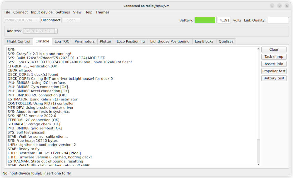
make cloadStart your Crazyflie and the python client. Connect the client to the Crazyflie and open the console log tab. Make sure you are running your app by looking for the line:
MYCONTROLLER: Waiting for activation ...Code language: HTTP (http)Now let’s activate our new controller! Open the parameter tab, find the stabilizer group and the controller parameter. Set it to 5 and check the console log that the out-of-tree controller was activated:
CONTROLLER: Using OutOfTree (5) controllerCode language: HTTP (http)That’s it! Your new controller is activated and the Crazyflie is ready to fly.
Note: In the client, the comment for the stabilizer.controller parameter will not contain the out-of-tree controller, and it will look like only values 0-4 are valid even though 5 also works.
Conclusions
In this post we have shown how to add a new controller to the Crazyflie firmware. The process for adding an estimator is very similar, and hopefully it should be easy to understand how to do it based on the example above.
As you can see, very little code (apart from the actual controller/estimator) is required to add your own controller or estimator, and we hope that it will enable you to put your energy into the actual control problem, rather than the nitty gritty details of the code.
Happy coding!