Month: July 2025

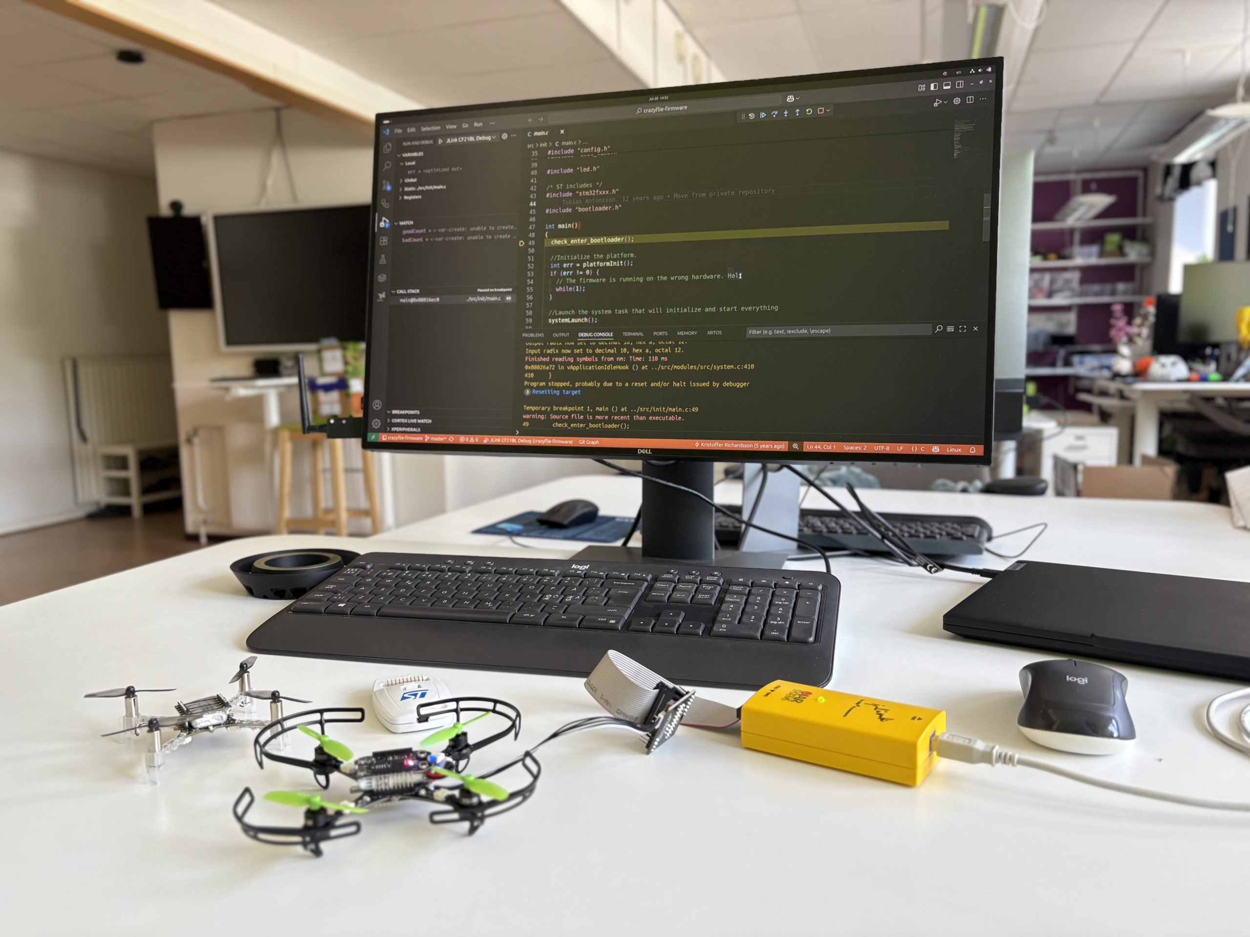
Debugging the Crazyflie using the debug-adapter kit gives you direct access to the STM32 with a hardware debugger. It makes it possible to pause execution, step through code, and inspect what’s happening in real time.

Even if you’re working mostly at a higher level, having this kind of visibility can be a huge time-saver when something unexpected happens. It’s a tool I use frequently when tracking down firmware issues or verifying low-level behavior.

We already have documentation for debugging the STM32 on the Crazyflie using ST-LINK and VS Code, but there are still a few missing pieces; like how to use J-Link, how to debug other platforms (like the Crazyflie 2.1 Brushless), and how enabling debug builds can help.

Debug Build

If you’re debugging and your breakpoints aren’t landing where you expect, or stepping seems unpredictable, or variables aren’t visible, it’s probably because the firmware was built with compiler optimizations enabled. When you select a debug build, the build system disables optimization by setting the compiler flag -O0, which preserves line-by-line correspondence between source code and machine instructions. This makes stepping and inspecting variables much more reliable.

To enable a debug build, you need to set the CONFIG_DEBUG option in your Kconfig configuration. You can do this, for example, by running make menuconfig in a terminal. Then navigate to Build and debug options and select Enable debug build. After changing Kconfig options, re-run make to rebuild the firmware with the new configuration.
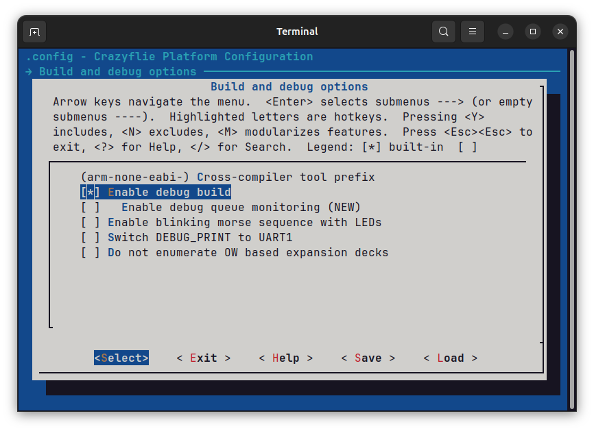
Enabling debug build Kconfig option through menuconfig

VS Code Debug Configuration

With debug builds enabled, you’ll get more predictable stepping and reliable breakpoints. The next step is setting up your debugger. Below is a launch.json configuration for VS Code that supports both ST-Link and J-Link, and works with Crazyflie 2.x and the 2.1 Brushless.

If you’re using a J-Link probe, you’ll need to install the J-Link software from Segger.

{
    // VS Code debug launch configurations for Crazyflie 2.x and 2.1 Brushless using J-Link and ST-Link
    "version": "0.2.0",
    "configurations": [
        {
            // ST-LINK configuration for Crazyflie 2.x
            "name": "STLink CF21 Debug",
            "cwd": "${workspaceRoot}",
            "executable": "${workspaceRoot}/build/cf2.elf",
            "request": "launch",
            "type": "cortex-debug",
            "device": "STM32F405",
            "svdFile": "${workspaceRoot}/tools/debug/STM32F405.svd",
            "servertype": "openocd",
            "configFiles": ["interface/stlink-v2.cfg", "target/stm32f4x.cfg"],
            "runToEntryPoint": "main",
            "preLaunchCommands": [
                "set mem inaccessible-by-default off",
                "enable breakpoint",
                "monitor reset"
            ]
        },
        {
            // ST-LINK configuration for Crazyflie 2.1 Brushless
            "name": "STLink CF21BL Debug",
            "cwd": "${workspaceRoot}",
            "executable": "${workspaceRoot}/build/cf21bl.elf",
            "request": "launch",
            "type": "cortex-debug",
            "device": "STM32F405",
            "svdFile": "${workspaceRoot}/tools/debug/STM32F405.svd",
            "servertype": "openocd",
            "configFiles": ["interface/stlink-v2.cfg", "target/stm32f4x.cfg"],
            "runToEntryPoint": "main",
            "preLaunchCommands": [
                "set mem inaccessible-by-default off",
                "enable breakpoint",
                "monitor reset"
            ]
        },
        {
            // J-Link configuration for Crazyflie 2.x
            "name": "JLink CF2 Debug",
            "cwd": "${workspaceRoot}",
            "executable": "${workspaceRoot}/build/cf2.elf",
            "request": "launch",
            "type": "cortex-debug",
            "device": "STM32F405RG",
            "svdFile": "${workspaceRoot}/tools/debug/STM32F405.svd",
            "servertype": "jlink",
            "runToEntryPoint": "main",
            "preLaunchCommands": [
                "set mem inaccessible-by-default off",
                "enable breakpoint",
                "monitor reset"
            ]
        },
        {
            // J-Link configuration for Crazyflie 2.1 Brushless
            "name": "JLink CF21BL Debug",
            "cwd": "${workspaceRoot}",
            "executable": "${workspaceRoot}/build/cf21bl.elf",
            "request": "launch",
            "type": "cortex-debug",
            "device": "STM32F405RG",
            "svdFile": "${workspaceRoot}/tools/debug/STM32F405.svd",
            "servertype": "jlink",
            "runToEntryPoint": "main",
            "preLaunchCommands": [
                "set mem inaccessible-by-default off",
                "enable breakpoint",
                "monitor reset"
            ]
        },
    ]
}Code language: JSON / JSON with Comments (json)

To use this setup with a different platform, like the Flapper, just change the executable field to point to the correct .elf file. By default, starting a debug session in VS Code will erase and reflash the firmware, so make sure the firmware is built beforehand. If you need to attach to a running target without flashing, you’ll need to modify the launch.json to skip loading the binary.

Today’s blogpost comes from Joseph La Delfa, who is currently doing his Industrial Post-Doc with Bitcraze.

The Qi deck and the Brushless charging dock allow you to start charging a Crazyflie quickly, without having to fiddle with a plug or a battery change. But when you need to charge 10 or more Crazyflies 2.x and don’t want the weight penalty of the Qi deck then some some other solutions are needed.

This blog post is about a couple of chargers I made for the Crazyflie 2.x for my research prototypes. I research interaction design, which often means building something new and then putting in the hands of a user and getting them to try it out. What is important in these scenarios is that when there is unexpected behavior, they don’t think that the prototype is bugging out or broken. One way to prevent this is to make things that have a higher quality to raise the expectations of the user. This can help them stay immersed in the interaction and not look over to me when there is unexpected behavior and say… “is this working properly?”

Wiring Harness for Drone Chi

This charger is essentially a pair of JST 2-pin extensions for a 1S battery charger that I soldered together. Then weaved them through some fake hanging plants. With the drones already looking like flowers for the Drone Chi project, they blended well into the fake plants and all the wires were well hidden. When you wanted to fly, you would disconnect the battery from the wiring harness. Plus it brings the nice experience of picking a flower from a bush before you start flying!

Magnetic Mantle Piece Charger for How To Train Your Drone

This charger allows 10 Crazyflies to charge from their USB ports, but on a bit of a statement piece charger that lived in the lounge room of a group of friends who were participating in a month-long user study during the How to Train Your Drone Project. This charger contained a powered USB hub with cables running through each of the medusa like tubes rising from the base. What made this charger special was the magnetic USB charging adapters (available widely on e-bay, amazon, temu etc) that were plugged into the the USB ports on the drone. These allowed you to securely place the drone on the charger in one action as the magnetic cables integrated into the charger were always close enough to the drone when you set it down, giving you a satisfying * click * every time! They also gave off a eerie blue glow which I think matched the Crazyflie well.

At Bitcraze we like making decks! When we released the Crazyflie 2.0 we were really excited about the new deck connector we put on the platform. Using this, it was suddenly possible to expand the platform, adding new, more complex functionalities years after the initial release. It’s something that we really like about the Crazyflie. Over the years we’ve released a bunch of decks and also updated a few of them as new, improved sensors became available.

Deck limitations

As the number of decks has increased, along with their complexity, we’ve started noticing some limitations. We’ve touched on this a while back in this blog post where you can find more details, but here’s a short summary:

  • Resource sharing in the STM32F4: Mainly DMA conflicts between different peripherals, like conflict for DMA using DSHOT on the Crazyflie 2.1 Brushless and the WS2812b driver for the LED-ring.
  • Bus arbitration and performance: Some decks make excessive use of some buses, which can cause issues with certain combinations like the LPS deck and micro-SD card deck.
  • Deck combinations and pins: As more interesting decks are released and we’re able to carry more weight, users want to combine more decks. Although we try to be smart with pin allocation there’s a limit on how you can combine the decks.
  • MCUs on decks: As the complexity increases, separate MCUs are also included on the decks. Although working well for offloading the main MCUs on the Crazyflie, the complexity quickly increases both for usage and for development. This is something we’ve seen with the AI deck for instance, which contains 2 MCUs.

Like suggested in the original blog post, the solution will be to move more intelligence onto the decks by putting MCUs on them. These MCUs can then use the hardware on the decks without sharing resources with the main Crazyflie MCU and can also help process the data to make the communication with the Crazyflie more high level. But doing this will of course then make the issue raised in the last point even worse. To mitigate this we need to have better control over the decks. Our proposed solution for this is adding a new MCU to the decks which acts as a controller. Being able to switch on/off power, bootstrap and control various aspects of the deck. Some of the features include:

  • Uniquely identify the deck and also identify the model of deck – This will replace the current 1-wire memory subsystem we have today
  • Uses minimal amount of pins, basically only using the I2C pins
  • Use the MCU pins as GPIOs or as various peripherals:
    • GPIO expander enables switching on/off onboard power supply, simplifying bootloading and saving power. It also enables bootstrapping of onboard MCUs, which can be used for selecting what output pins to use for various functionality
    • Bridge I2C to SPI/UART for bootloading of onboard MCU. This would of course be much slower than using the SPI/UART but would simplify bootloading and not need pins allocated on the expansion connector
  • Bootstrapping the board makes it possible to to implement support for duplicate decks, for instance selecting what UART (1 or 2) on startup makes it possible for the driver on the Crazyflie to start up each deck and select what UART is used.

Our implementation

For our implementation of this system we have selected the STM32C011 MCU, as it comes in various packages from very small to slightly larger, so it’s possible to solder by hand. It also has the features we needed. To maximize the the flexibility of the system we don’t want to program in the I2C addresses in production. Even if you disregard the fact that the address might conflict with other I2C devices in the future, it will definitely conflict if you add two of the same type of deck.

To fix this we will automatically detect all the deck-ctrl MCUs on the bus and then move them to individual addresses. This will enable us to change the addresses in the future if there are collisions and also allows multiple instances of the same deck attached at the same time. Below is a video demonstrating this in action, implemented on custom development decks we’ve made for simplifying firmware development. Each deck runs the same deck-ctrl firmware and all 3 are auto-detected at startup.

The future

The current solution will be used on our next two upcoming decks: the new LED deck and the new Lighthouse deck. As we get closer to their release we will publish the firmware for the deck-ctrl MCU on GitHub. If the design turns out well we will keep rolling it out to future decks, increasing the flexibility of the deck expansion system even more.

You might already be familiar with the Crazyflie’s presence in numerous publications across various research fields. However, in this blog post, we’ll return to the basics and showcase some robotics concepts that can be taught using our platform.
The Crazyflie has already found its way into several classrooms such as the “Introduction to Robotics” in the Mechanical & Aerospace Engineering Department at Princeton University, the “Introduction to Control of Unmanned Aerial Vehicles” at UC Berkeley and the “Embedded control systems” at Chalmers University of Technology.
Whether you’re designing a robotics course for undergraduates or developing advanced labs for graduate students, here’s some fields where the Crazyflie can help your students grasp the fundamentals of modern robotics.

Basic Drone Principles

How does the quadcopter generate enough thrust? In which direction should the motors spin? How does the shape of a propeller affect performance?
As an introduction to drones and specifically quadcopters, students can explore these basic principles behind how they work. Then, by flying them, they can better understand the three axes of motion, roll, pitch and yaw and even find out their limitations, such as the ground effect.

Control Systems

What is the difference between controllers? How does a different controller tuning affect performance? How does an estimator work? What types of commands can be sent to a drone?
The Crazyflie platform offers a rich “playground” for exploring the stabilization process from sensor acquisition to motor control, that we often call “stabilizer module“. This includes a variety of controllers, estimators and commanders that can be modified to visualize results in the real world. Also, with the firmware being open-source and modular, it is relatively easy to build your own controller or estimator and integrate it to the platform.

Localization

How can a drone know its position and orientation in 3D space? What is the difference between a local and a global positioning system?
With a wide variety of deck sensors and positioning systems, students can find ways to control the Crazyflie through relative or absolute position/attitude commands. The different sensing methods used in these systems are also interesting to explore – for example, IR signals from the Lighthouse Positioning System, UWB radio from the Loco Positioning System, or optical flow data from the Flow deck v2.

Autonomous Navigation

How could the Crazyflie perform a collision-free trajectory? What is the most efficient way of flying from point A to point B?
In the field of autonomous navigation, the Crazyflie can be treated like any other moving robot by applying existing path planning algorithms or testing newly developed ones. Environment-aware problems are always exciting to work on and the Multi-ranger deck makes them feasible.

Swarm Robotics

What happens when you add another Crazyflie to your setup? How could multiple Crazyflies operate in a swarm? How could you make sure that they won’t collide? What is the difference between a centralized and a decentralized swarm?
Scaling a system up is always challenging but also fascinating. The examples provided in our Python library help you get a swarm in the air, but it’s up to you and your students to explore how the Crazyflies should coordinate and cooperate.

Small Drone, Big Educational Impact

The Crazyflie ecosystem is a fully capable robotics lab in the palm of your hand. Its flexibility, safety, and robust API support make it ideal for hands-on learning in a wide variety of robotics fields. Integrating the Crazyflie into a university robotics curriculum, gives students the chance to explore, test, fail, and fly their way to mastery.