Author: Kristoffer Richardsson

We have now worked a few weeks on the new TDoA 3 mode for the Loco Positioning System. We are happy with the results so far and think we managed to do what we aimed for: removing the single point of failure in anchor 0 and supporting many anchors as well as larger spaces.


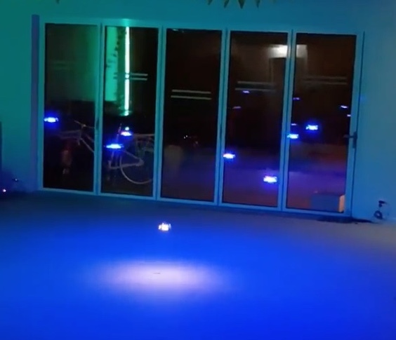
We finished off last week by setting up a system with 20 anchors covering two rooms down in the lunch area of the office. We managed to fly a scripted autonomous flight between two rooms.

Work so far on the anchors

Messages from the anchors are now transmitted at random times, which removes the dependency on anchor 0 that used to act as a master that all other anchors were synchronized to. The drawback is that we get problems with collisions when two anchors happens to transmit at the same time. Experiments showed that at 400 packets/s (system rate) we ended up at a packet loss of around 15% and 340 TDoA measurements/s sent to the kalman filter for position estimation.  We figured that this was acceptable level and added an algorithm in the anchors that reduces the transmission rate based on the number of anchors around them. If more anchors are added to a room they all reduce their transmission rate to target 400 packets/s in total system rate.

The anchors continuously keeps track of the clock drift of all other anchors by listening to the messages that are transmitted. We know that clocks do not change frequency suddenly and can use this fact to filter the clock correction to reduce noise in the data. Outliers are detected and removed and the resulting correction is low pass filtered. We have done some experiments on using this information and compare it to the time stamp of a received message to detect if the time stamp is corrupt or not, but this idea requires more work.

One interesting feature of the anchors is the limited CPU power that is available. The strategy we have chosen to handle this fact has been to create an algorithm that is efficient when handling messages. A timer based maintenance algorithm (@1 Hz) examines the received data and makes demissions on which anchors to include in the messages in the future as well as purges old data.

The Crazyflie

The implementation in the Crazyflie is fairly straight forward. The biggest change to TDoA 2 is that we now can handle a dynamic number of anchors and have to chose what data to store and what to discard. We  have also extracted the actual TDoA algorithm into a module to separate it from the TDoA 3 protocol. The clock correction filtering algorithm from the anchors has also been implemented in the Crazyflie. 

An experimental module test has been added where the TDoA module is built and run on a PC using data recorded from a sniffer. We get repeatability as well as better tools for debugging and this is something that we should explore further.

Work remaining 

The estimated position in the Crazyflie is still more noisy than in TDoA 2 and we would like to improve it to at least the same level. We see that we have outliers in the TDoA measurements that makes the Crazyflie go off in a random direction from time to time, we believe it should be possible to get rid of most of these.

The code is fairly hackish and there are no structured unit or module tests to verify functionality. So far the work has been in an exploratory phase but we are getting closer to a set of algorithms that we are happy with and that are  worth testing. 

We have not done any work on the client side, that is support for visualizing and configuring the system. This is a substantial amount of work and we will not officially release TDoA 3 until this is finished.

How to try it out

If you are interested in trying TDoA 3 out your self, it is all available on github. There are no hardware changes and if you have a Loco Positioning system it should work just fine. There is a short description on the wiki of how to compile and configure the system. The anchor supports both TDoA 2 and TDoA 3 through configuration while the Crazyflie has to be recompiled to change between the two. The support in the client is limited but will basically handle anchors 0 – 7.

Have fun!
First of all we are happy to announce that (almost) all products have been stocked in the new warehouse and are now shipping! The last orders that were on hold are on their way out and new orders placed in the store will now be shipped again within a few days.

We released the TDoA mode, a.k.a. swarm mode of the Loco Positioning System back in January. TDoA supports positioning of many Crazyflies simultaneously which makes it possible to fly a swarm of Crazyflies with the LPS system. The release in January was actually the second iteration of the TDoA implementation (the first iteration was never publicly released) and it is also known as TDoA 2.

TDoA 2 works well but there are a couple of snags that we would like to fix and we have now started the work on the next iteration, TDoA 3. 

Single point of failure

TDoA 2 is based on a fixed transmission schedule with time slots when each anchor transmits its ranging packet. All anchors listen to anchor 0 and use the reception of a packet from anchor 0 to figure out when to transmit. The problem with this solution is that if anchor 0 stops transmitting for some reason the full system will stop transmitting positioning information. This is clearly a property that would be nice to get rid of.

Limited number of anchors

The packets in the TDoA 2 protocol have 8 slots for anchor data that are implicitly addressed through the position in the packet. First slot is anchor 0, second slot anchor 1 and so on. This setup is easy to use but creates an upper limit of 8 anchors in the system.

The maximum radio reach of an anchor depends mainly on the transmitted power and the environment. This distance, in combination with a maximum of 8 anchors and that all anchors must be in range of anchor 0, sets an upper limit of the volume that an LPS system can cover, basically one large room. When we designed TDoA 2 we were happy to be able to support a swarm of Crazyflies and did not really bother too much about the covered volume. We get more and more questions about larger areas and more anchors though and it would be nice to have a positioning system that could be expanded.

The solution – maybe…

What we want to do in TDoA 3 is to transmit packets at random times and add functionality to handle the collisions and packet loss that will happen in a system like this. The idea is that the even if some data is lost, the receiving side will get enough packets to be able to calculate the distance to other anchors or a position as needed. By removing the time slots and synchronization to anchor 0, we get rid of the single point of failure. 

In the TDoA 3 protocol, we have added explicit ids to the anchor data, and thus removed the implicit addressing of anchors. We have 8 bits for anchor ids and the system will handle 256 anchors for sure. We do think that it will be possible to design larger systems though by reusing ids and making sure that the radio ranges of anchors with the same ids do not overlap.

The UWB radios have a nice property that makes this a bit easier to handle collisions than one might first think, if they receive two packets at the same time, they will most likely “pick” one of the packets and discard the other. The drawback is that it is likely that the receive time of the packet will be less accurate. We are not completely sure it will be possible to detect and handle the added noise in the time stamps but we have good hope!

The current state of the project

Last week we did a proof of concept hack when we modified the old TDoA 2 implementation to transmit at random times, as well as minor modifications to handle random receive order of packets. It all worked out beautifully and we could fly a short sequence in the office with the new mode. The estimated position was a bit more shaky which is not surprising, considering that the receive times are more noisy.

We have just started with the real deal.  We have designed a draft spec of the protocol and have also started to implement the new protocol on top of the old TDoA2 algorithms in the anchors and the Crazyflie to get started. Next steps will be to introduce random transmission times, dynamic anchor management and better error handling. The TDoA 3 implementation will exist in parallel with the current TDoA2 implementation and should not interfere.

If you want to contribute, are interested in what we do or have some input, please comment this blog post or contact us in any other way.


We are excited to announce that the Crazyflie 2.0 and the STEM bundle has been chosen by Udacity for their Flying Car Nanodegree Program. For the students that want to try out their skills on a real world flying drone, the core curriculum has been augmented with supplemental lessons and Udacity announce that they will provide thorough instructions for the Crazyflie.


Udacity is providing on-line learning and their mission is 

“to democratize education through the offering of world-class higher education opportunities that are accessible, flexible, and economical”

We are super happy that Udacity likes the Crazyflie and that more people will have the opportunity to explore the world of robotics!

Qualisys is a Motion Capture (Mocap) system manufacturer based in Gothenburg in Sweden. Since we are also based in Sweden, Qualisys have been able to visit us a couple of times and we now have one of their Motion capture system installed at the office. This collaboration allows us to have access to a Mocap system, something we did not have previously. It means that we can better support people using motion capture systems with Crazyflie.

We are currently implementing support for Qualisys in the Crazyswarm project. Crazyswarm currently supports a couple of motion capture system including Vicon and Optitrack, with the addition of Qualisys we and everyone with a Qualisys system will be able to fly swarms of Crazyflie in their mocap.

We are also planning on having a combined booth, Bitcraze and Qualisys, at IROS 2018. We are planning to demo flying both with the Mocap and with the Loco Positioning System. We will keep updating on this when we have more details.

We look forward to this collaboration since it will allow us to use and better support motion capture positioning for the Crazyflie.

We have been lucky get the opportunity to use a motion capture system from Qualisys in our flight lab. The Qualisys system is a camera based system that is using IR-cameras to track objects with sub-millimeter precision! The cameras are designed to measure the position and track small reflective marker balls that are fixed to the object to be tracked with high accuracy. By using multiple cameras shooting from different angles it is possible for the system to calculate the 3D position of a marker in space. By mounting multiple markers on an object the system can also identify the object as well as its orientation in space. Very cool!

We have started to look at how to add support in our ecosystem for the Qualisys system as well as other “external” positioning systems, external in this context is systems that calculate the position outside the Crazyflie. There is already great support for external positioning in the CrazySwarm project by the USC-ACTLab, but we are now looking at light weight support in the python client. We are not sure what we will add but ideas are on the lines of viewing an external position in the client, feed an external position into the Crazyflie for autonomous flight and maybe a simple trajectory sequencer.

MoCap Deck

We have also started to design a MoCap Deck to make it easy to mount reflective markers on the Crazyflie. Our design goals include:
* light weight
* easy to use
* support for multiple configurations to enable identification of individuals
* the possibility to add a button for human interaction

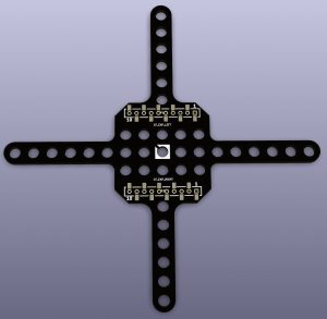
The current design of the MoCap Deck

The suggested design of the MoCap Deck

Any feedback on the MoCap Deck and ideas for functionality to add to the client is welcome! Please add a comment to this blog post or send us an email.

We will write more about the Qualisys system later on, stay tuned!

As I wrote about in a previous blog post, I have been working on an anchor position estimation algorithm in the Crazyflie Client. The algoritm uses ranging data from the Loco Positioning system to estimate where the anchors are located, and thus remove the need to measure their positions in the room. I have finally reached a point where I think it is good enough to let it out from the lab and it has been pushed to the client repository.

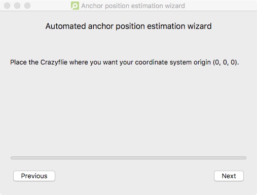
A button has been added to the Loco Positioning tab that opens a wizard. In the wizard the user is asked to place the Crazyflie in certain positions to record ranges and define the coordinate system. If all goes well, the estimated anchor positions are transfered to the anchor position fields in the Loco Positioning tab. If the user is happy with the result the next step is to write the positions to the anchors and start flying!

Now to the disclaimer: the results may not always be perfect – surprise! We have not tested the algorithm a lot but it seems to give decent results, at least it can be useful as a base for manual corrections and sanity checks. Some of the estimated positions are pretty good, while others might be a meter or so off. The conclusion is that you should not trust it blindly, check that the estimated positions seem reasonable before flying.

Currently the system only supports Two way ranging, but extending it to TDoA should not be too complicated. There are probably many possible improvements that can be done, and we hope that everyone that finds this interesting and have ideas of how to do it will give it a go. After all, it is open source and we would love to see contributions refining the functionality, now that there is a base to build from.

Any feed back is welcome, let us know if it works or not in your setup!

We have recently released a few products with optical flow sensors (the Flow deck and the Flow Breakout board) without really talking about the concept of optical flow. So we though we would dedicate this weeks post to it.

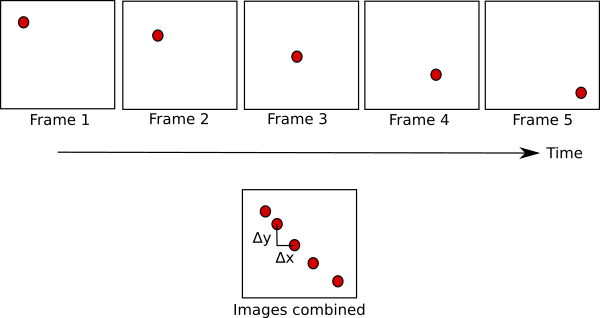
The most common example of optical flow is probably a computer mouse. Turning the mouse over you’ll see a strong light that’s used to illuminate the surface so that a camera can clearly see the surface. When running, the camera will identify features in the surface below it and track their motion between frames. As you move the mouse to the left, features will move to the right.  

In the example below you can see a feature being tracked over time.

optical flow

The feature is tracked from frame to frame and the output is the distance that the feature moved since the previous frame. 

The functionality of an optical flow sensor of course depends on being able to find features to track, a surface that is very uniform will be hard to track since all the frames will look the same. If you’ve ever tried using a mouse on a glass table or reflective surface you’ve probably seen that it doesn’t work.

The same concept is used in our Flow products. It also happens that the manufacturer of the chip we use, PixArt, is a world leader in optical mouse sensors. They have applied the same concepts as for the mouse but with a different lens that gives the camera the ability to track features further away (80mm – inf). Like the mouse this is dependent on finding features to track, which might be problematic on poorly lit surfaces or on surfaces that are very uniformly colored. On the other hand if the area is too lit up from the ceiling above you when you fly you might start tracking your own shadow on the floor.

One of the issues with using optical tracking from a flying platform is that you need to know the distance to the features. In the case of the mouse you will know that the features are right under the mouse, but in the case of the flying platform you won’t know this from only looking at the image. Think about sitting on a plane and watching the ground move, it’s really slow. But your movement along the ground will actually be really fast. For our Flow products we’ve added the VL53L0x ToF distance sensor to measure the distance to the surface that’s being tracked. This completest the equation so if you’re further away from the features that are being tracked this will be taken into account. Note that the accuracy of the tracking will decrease when the distance increases since the difference between frames becomes smaller and harder to detect.

An optical flow sensor can also be used to track motion of other objects instead. Suppose the optical flow sensor is fixed and pointing sideways, then it will detect objects passing in front of it, for instance counting people passing a doorway, or it could be used as a touch less mouse.


We are going to China and Maker Faire Shenzhen Nov 11-12.

Come and meet us in the Seeed Studio stand, we love talking to makers and geeks!

We have started working on a demo and the plan is to show an autonomously flying Crazyflie using the Flow deck for positioning. If you are in the area, drop by at Liuxiandong Campus, Shenzhen Polytechnic and say hi!

See you there!


One of the pain points when setting up the Loco Positioning system is to measure the anchor positions and enter them into the system. I wanted to see if I could automate this task and let the system calculate the positions, and if so understand what kind of precision to expect. I have spent a few Fun Fridays playing with this problem and this is what I have found so far.

The problem can be broken down into two parts:
1. How to calculate the anchor positions. What data is required?
2. How to define the coordinate system. To make it useful the user must to be able to define the coordinate system in a simple way.

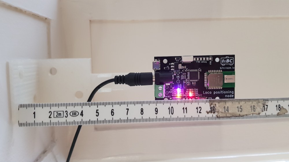
Anchor and ruler

How to calculate the anchor positions

The general idea of how to calculate the anchor positions is to set up a system of equations describing the distances between the anchors and/or the Crayzflie and solve for the anchor positions. The equations will be non linear and the (possibly naive) plan is to use the Gauss Newton method to solve the system.

To understand how to calculate the anchor positions we must first take a look at the data that is available. The Loco Positioning system can be run in two different modes: Two Way ranging (default mode) and TDoA.

Two way ranging

In the Two Way ranging mode we measure the distance between each anchor and the Crazyflie and to get enough data we must record ranging data for multiple positions. The anchor positions are unknown, and for each new Crazyflie position we add yet a new unknown position, on the other hand we measure the ranges to the anchors so these are knowns. 

The equations used are simply to calculate the distance between the assumed position of each anchor and the Crazyflie and then subtracting it from the measured distance.

TDoA

In TDoA we measure the Time Difference of Arrival, that is the difference in distance to two anchors from the Crazyflie’s position. It is probably possible to use this information, but I was looking for a different solution here. In our new TDoA implementation that we have been playing with a bit, we get the distance between all anchors (calculated in the anchors) as a side effect. 

In this case the Crazflie is not really needed and the equations describe the distance between assumed anchor positions versus measured distances.

How to define the coordinate system

To get a useable positioning system, the coordinate system must be well defined and oriented in a practical direction. For example when writing a script you probably want (0, 0, 0) to be at some specific spot, the X-axis pointing in a certain direction, the Z-axis to point up and so on. My initial idea was to use the anchors to define the coordinate system, use anchor 0 as (0, 0, 0), let the X-axis pass through anchor 1 and so on. Just by looking at our flight lab I realised that this would be too limiting and decided that the coordinate system should be completely disconnected from the anchor positions, but still easy to define. I also realised that a really good way to tell the system about the desired coordinate system would be to move the Crazyflie around in space to show what you want. The solution is to place the Crazyflie at certain positions and click a button to record data at these positions. The steps I have chosen are:

  1. Place the Crazyflie at (0, 0, 0)
  2. Place the Crazyflie on the X-axis, X > 0
  3. Place the Crazyflie in the XY-plane, Y > 0
  4. Move the Crazyflie around in the space with continuous recording of data

In this scheme the XY-plane is typically the floor.

Results

I have written basic implementations for both the Two Way ranging and TDoA modes and they seem to work reasonably well in simulations. I have also tested the Two Way ranging algorithm in our flight lab with mixed results. The solution converged in most cases but not always. When converging the estimated anchor positions ended up in the right region but some were off by up to a meter. Finally I did run the algorithm and fed the result into the system and managed to fly using the estimated positions which I find encouraging.

I will continue to work on this as a Friday Fun project and maybe it will make its way into the client code base at some point in the future? There are probably better ways to estimate the anchor positions and more clever algorithms, feel free to share them in the comments.


We announced the release of the Flow breakout board yesterday and we were happy to finally get it into the store. A few hours later we got some samples of the first production batch to the office and we discovered that we have messed up a bit.

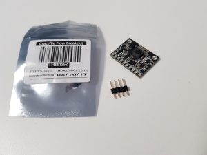
First of all there has been a mixup when the pin headers were packed into the plastic bag, there are only 4 pins instead of the intended 10. We are sorry about this and if you get a bag like this, it is a standard pin header and the best way to fix it is to buy it in your local store.

The second problem is only cosmetic, the print on the bag states “Crazyflie Flow Breakout”. The Flow breakout is not intended for the Crazyflie but can of course be used with virtually any other hardware such as an Arduino for instance.

We were very eager to get the Flow Breakout, with its awesome functionality, into the store as quickly as possible, but maybe we were a bit too fast. The problems will be fixed in the next batch and for those of you who get a bag with the wrong pin header, we are really sorry! We hope it will not be too much of an inconvenience.