Something we seldom write about on the blog is production and supply chain. It’s a big part of what we do, both in time and business wise. Even though we spend most of our time on firmware/software we’re actually only selling hardware. So this blog-post is about how we’ve set this up and the problems we’ve been facing the last month due to our 3rd party warehouse moving to a new location.
The current set-up
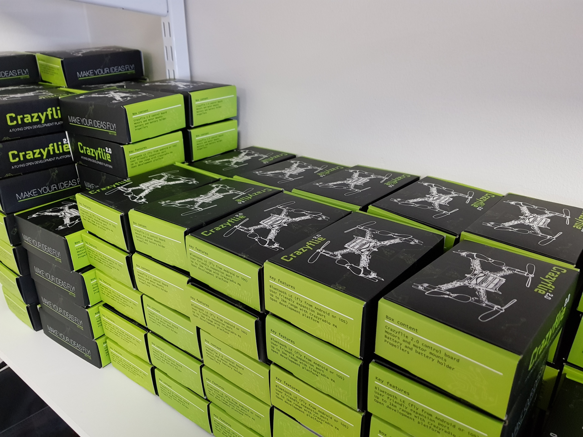
Currently we’re using Seeedstudio for our manufacturing. They do varying batch sizes, but most of the batches we produce are between 300 and 2000 units. We’ve been experimenting a bit with varying size of batches, too large and you tie up too much funds in stock while with smaller batches you spend most of you’re time tending to manufacturing. Another issue with large batches are things like battery shelve life and changing market (i.e suddenly some parts are EOL or have been replaced when it’s time for the next batch). Finding a good level for different products depending on production cost, complexity and shelf-life is tricky.
After production the goods are moved to a number of warehouses. Part of the goods are warehoused at Seeedstudio, part of them are sent to our 3rd party warehouse in Hong Kong serviced by Shipwire and a small amount is sent to our office for testing/development/customers. The products in Seeedstudio’s warehouses services a number of distributors though their wholesale channels as well as end-users though their Bazaar. We service our E-store though Shipwire in Hong Kong and a few customer though our Swedish office.
Scaling up
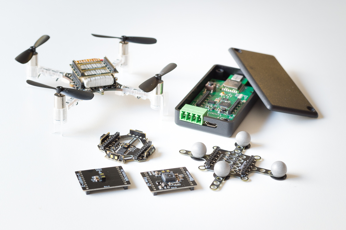
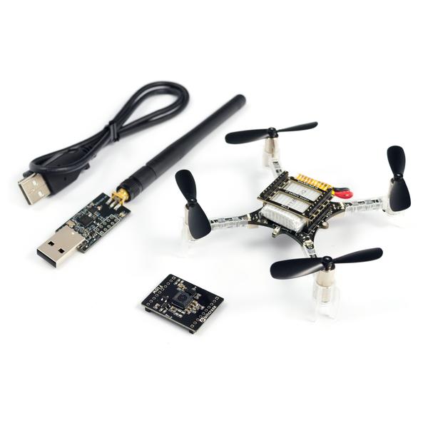
Since the end of last year we’ve seen an increase of sales, which we are of course really happy about! More sales will mean more resources for development which translates into more awesome products and features for everyone. The problem is that it takes time to scale up the supply chain on the back. Today we have have 27 SKUs and 7 bundle SKUs “virtually” made out of combining products into bundles. Out the 27 SKUs we control the manufacturing of 17 SKUs (like PCBs and plastic parts) and 5 SKUs are things we buy (like the USB-cable). Typically the lead time for simpler products is 1 month and more complex products 2 months, with an additional lead-time of at least a week to reach our Hong Kong warehouse and become available in the E-store. Creating bundles by “virtually” tying together a number of products is great since it gives us more flexibility but if one of the bundled SKUs is out of stock the bundle will also be our of stock.
Controlling this complex situation while scaling up for larger sales has proved challenging, also when everything works as expected (see below). Most of our customers have gotten their things in time, but we’ve had to put a lot of hours into juggling products around between warehouses to make it happen.
Warehouse issues
Back in February we were notified by Shipwire that they would be moving the operation to a new warehouse in Shenzhen/Hong Kong. The timeline that was communicated was that the inventory would be offline 3rd – 6th of April. This might seem optimistic for a warehouse that is about 10 000 m2, but since they have a large amount of warehouses around the globe we assumed they would pull this off. Unfortunately this wasn’t the case, a number of factors played in to delay the move. Since the first week of delays the expected timeline has been “next week”, which unfortunately hasn’t held. Finally we’re at a point where our old inventory has been moved into the new warehouse and is available. The next problem we’re facing is getting our incoming goods into the inventory, which is currently expected to be finished by the end of this week. To say the least we’re unhappy about this situation, but unfortunately we have had very little control. We don’t have a large number of products available in any other warehouse so we haven’t been able to “switch over” to another solution. We’ve done our best to keep the effected customers updated on the situation and calling support every day to get an update.
Moving forward
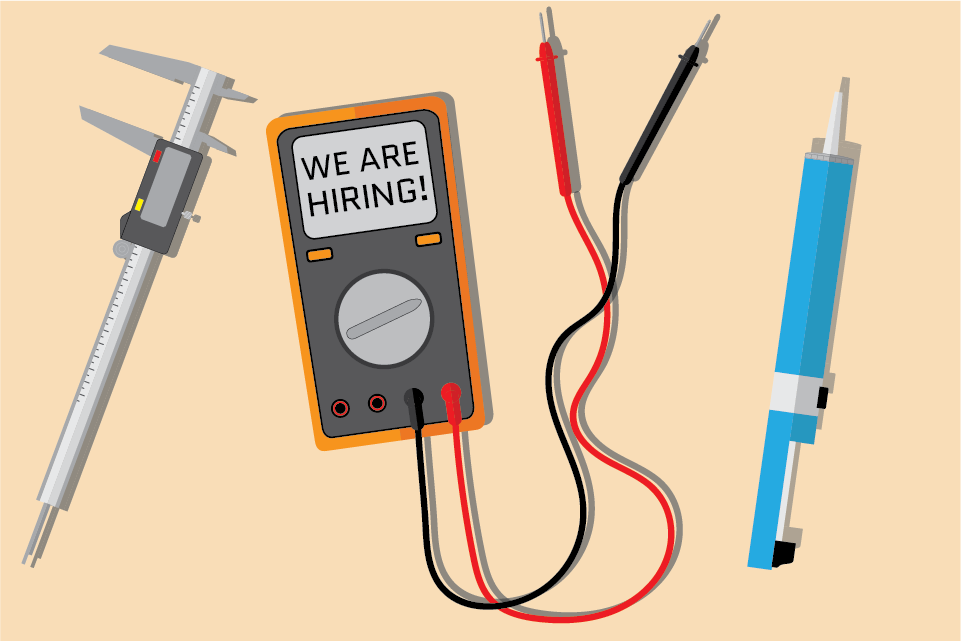
We’re a small team of 5 people and we’ve always been most focused on product development. It’s what we like to do and it’s what we’re best at. So an easy way forward would be to pay someone else to handle all of the above. Unfortunately this has proven to be tricky for us. Basically handing over everything that generates revenue for our company to someone else is a huge risk, to say the least. So we’ve realized that this has to be a central part of what we do, just like development. This was the main reason for starting our own E-store last year and it’s something we’re continuously working on improving.
Moving forward the overall goal is to minimize the work spent on production and stock management while making sure to not run out of stock or tie up all our funds in stock. We think that one key to this is being proactive instead of reactive. So we have integrated this into our daily work just as much as development. Next to the “development” board with stories/tasks we have an even bigger kanban board with production/logistics/warehouses and it’s something that is constantly part of the planning/status meetings. We’ve also been gearing up for producing batches of popular products more often and increasing the batch sizes to meet the increased demand and to lower the risk of being out of stock. The last part is an internal system we’ve been developing during the last couple of years that keeps track of stock, production, customer shipments and stats in general. More on this in a future blog-post!