Author: Marcus

This weekend we spent at the Maker Faire in Rome and got to meet lots of fellow geeks and makers. Even though it was busy times at the Bitcraze booth, we got a chance to walk around a bit and see other projects. It’s really inspiring to see what people come up with! It was also the first time we got the chance to show off the new Crazyflie 2.0 to the public and the feedback was really positive. We have realized that we might be a bit wide in our description of the new platform. There’s lots of new features that we are very eager to talk about, but maybe we should focus a bit more on the biggest improvements. With two weeks left on the pre-order we have been trying really hard to get some extra attention for the new platform, but haven’t really succeeded yet. This might be one of the reasons.

So even though there’s lots of new features we would really like to highlight the new expansion port. It’s been something that we have been talking about internally for a while now and we are really excited that we managed to fit it in. Like we wrote in an earlier post we used some exotic use-cases to figure out what to include in the expansion header. For example this resulted in the ability to charge the battery from the expansion board, like we are doing with the Qi wireless charging expansion board. Since the Crazyflie 2.0 has the ability to connect multiple expansion boards (both on top and bottom) we also needed some way to determine what boards are added. So one of the pins in the port is used as a 1-wire memory buss. Each expansion board has a 1-wire memory that allows identification of the board, it’s revision and what resources it uses. This way we can adapt the features available from the computer client or mobile device when the platform is connected.

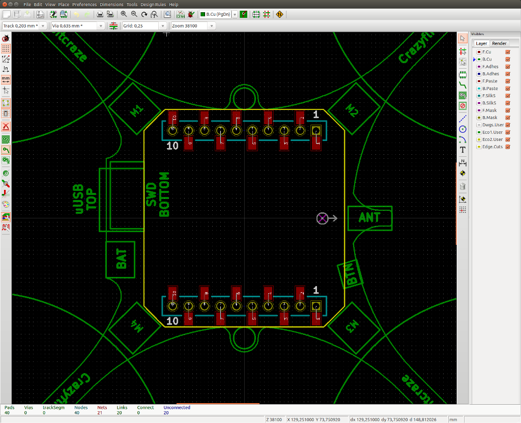
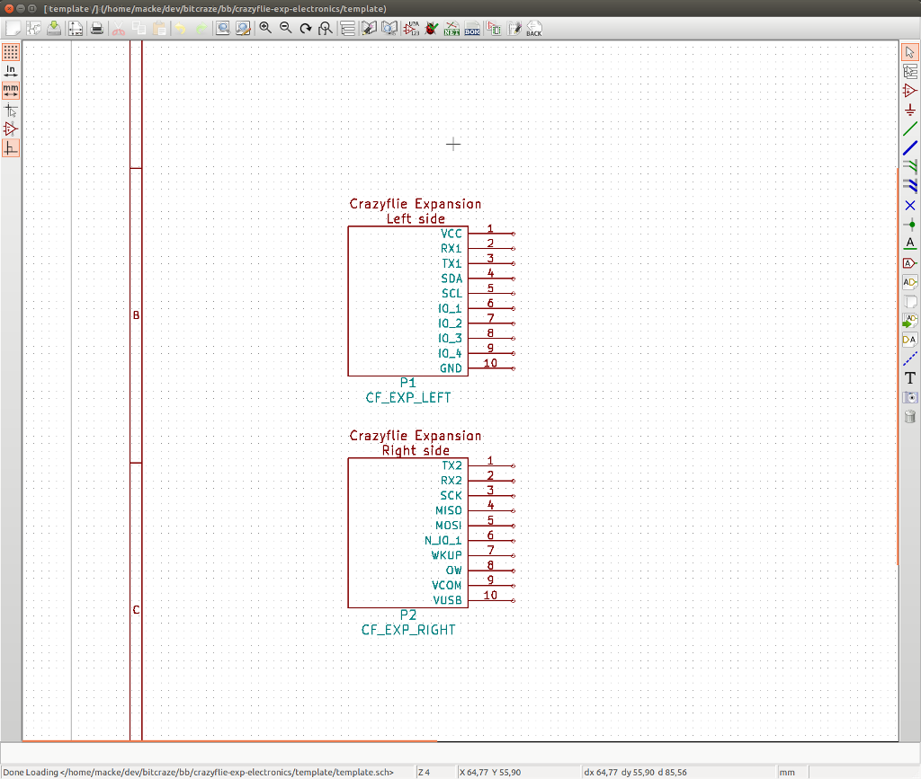
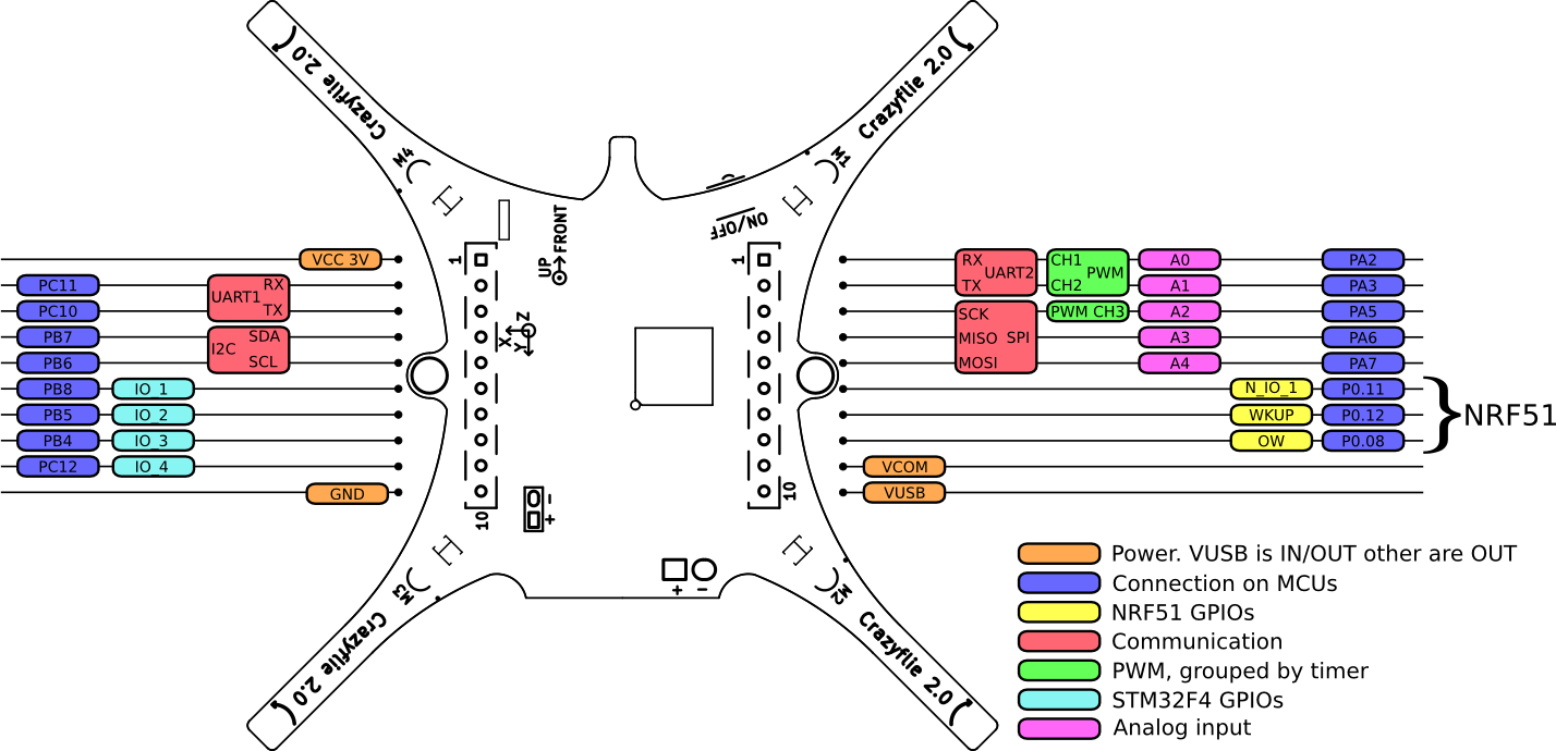
Below is an overview of what’s available in the expansion port:

Crazyflie 2.0 expansion connector

For the pre-order we have managed to include 4 expansion boards: the LED-expansion, the Qi wireless charging expansion, the breakout expansion and the prototyping expansion. Aside from these boards we also have some prototypes of more expansions. Before the pre-order we were working really hard on a GPS expansion board, but in the end we didn’t think the current prototype had enough precision to launch. We reached about 10-20 meters accuracy with locking times of about 2-3 minutes and didn’t have time to spin another prototype. During the fall we will work on perfecting the design so we reach a level of performance that we feel is good enough.

We also have a prototype for a distance sensor to be used for precision landing. After looking for a solution for a while we finally found the VL6180, a time of flight sensor from ST. The range is not very long, but combined with the high precision pressure sensor mounted on the Crazyflie 2.0 we think the result can be very good. We also have an uSD expansion that we are currently testing.

After getting feedback from the visitors we met at the Maker Faire we have also decided that we will be designing an Edison adapter expansion for the Crazyflie 2.0. The Edison board is fairly small and light, so it should be possible to design an expansion board that has the 70-pin expansion connector featured on the Edison. Our plan is to use some of the interfaces in our expansion board to connect to the Edison, like I2C, UART and SPI.

Last but not least we are also working on an analog FPV expansion board. It’s still just an early prototype, but we think it’s something that a lot of users might be interested in.

As we will continue making more and more boards we also hope the community will take the opportunity to do so as well. We will soon release templates for KiCad making it really quick to get started. What board would you like to make? Let us know what you think about the new expansion port. Do you have any ideas for boards or any comments about our planned ones? We would love to get some feedback!

We would also like to say congratulations to Mihir Garimella on being one of the winners of the Google Science Faire 2014 with his project the Flybot! He used the Crazyflie to work on escape maneuvers similar to those of fruit flies. Really great work!


We are really happy to announce that we are starting the pre-order for the Crazyflie 2.0 today! After spending nearly 10 months doing development, we have reached a point where we are very happy with the design and the performance. Now all we have to do is to kick off the production and that’s where the pre-order comes in.

During the next three weeks we will be taking pre-orders for the Crazyflie 2.0 and related products. After the three weeks has passed we will start the production and the current estimate for shipping the products is the second week of December. As a reward to users that want to help us out by pre-ordering our products, we are lowering the prices with about 15% until the 16th of October when the pre-order ends.

So, just to clarify:

  • Pre-order end: 16th of October
  • Estimated shipping: Second week of December

If you want to know more about the Crazyflie 2.0 and what it’s about, then have a look at the Crazyflie 2.0 product page. It explains a bit about the communication (Bluetooth LE and Crazyradio), the expansion boards and gives you an idea what you could use the platform for. The Crazyflie 2.0 developed with developers in mind, so it features thins like wireless firmware upgrade, real-time parameter setting/getting and data logging using graphs. To make it easier for developers to get going we provide a pre-installed virtual machine that contains most of our tool-chains for building firmware and software, as well as KiCad for the hardware design.

For the Crazyflie 2.0 pre-order we aren’t just making the Crazyflie 2.0 available, we are launching a full set of products to support it. Here’s the list of the main products and the expansion boards that are included in the pre-order:

  • Crazyflie 2.0: The next generation of our flying open development platform with lots of new features
  • Crazyradio PA: The same mechanical footprint and price as the current Crazyradio, but now with a power amplifier that we have tested to above 1km range (line-of-sight) with the Crazyflie 2.0
  • Debug adapter kit: An easy way to debug the nRF51 and STM32F4 on the Crazyflie 2.0 by using an adapter board for connecting a standard 20-pin/100mil JTAG or 10-pin/50mil Cortex-debug cable
  • LED-ring expansion board: Fly into the night in style with this expansion board featuring 12 bright RGB LEDs that can be individually controlled and two strong white front-facing LEDs
  • Qi expansion board: Charge your Crazyflie 2.0 without any wires with this inductive charging expansion board using Qi
  • Breakout expansion board: Easy solderless prototyping with a board designed to fit a breadboard to try out your designs on the ground
  • Prototype expansion board: With space for prototyping and access to all the pins in the Crazyflie 2.0 expansion port there’s lots of possibilities with this board

We are also including all the spare parts in the pre-order to make sure that everyone gets a chance to get what they need together with their Crazyflie 2.0. Here’s the list of parts:

For the release we wanted to make a video explaining a bit the new platform, but since we have been really short on time we’re not done yet. Instead we are publishing a short video showing the Crazyflie 2.0 in action together with the LED-ring expansion board. The video also features the traffic light hack we did a few weeks ago.

Have a look at the Getting Started page for the Crazyflie 2.0 for assembly instructions or the wiki documentation for the project to see how to assemble the new solderless Crazyflie. There’s also some Expansion port documentation available as well as User Guide. We are still working on filling out more of the documentation, so bare with us. With the hardware completed we are now refocusing on the firmware and software. We have built in lots of neat features into the new Crazyflie 2.0 hardware that we now need to add software support for. So over the coming months we will be working on the iOS/Android apps and the Crazyflie PC client as well as the firmware. We will of course keep everyone updated of the progress here on our blog. Once the Crazyflie 2.0 products start shipping we will publish all the code and hardware design on our GitHub.

Starting with the pre-order of the Crazyflie 2.0 we are also lowering the price for the current version of the Crazyflie. The Crazyflie Nano Quadcopter 10-kit is lowered from $149 to $116 and the bundle with the Crazyradio is lowered from $179 to $146. So if you can’t wait until December then have a look at the current version over at Seeedstudio.

Finally it’s getting really close and we are very excited to say that the pre-order of the Crazyflie 2.0 will start this week! We will post more details about it during the week, until then here’s a short teaser from our release video :-)


The last couple of weeks we have been spent on finishing the testing of the hardware and preparing lots of practical things for the production of the new Crazyflie 2.0. With almost all the hardware finished, we are now working hard on preparing for the pre-order. The number of products that are included in the Crazyflie 2.0 launch is a lot more than we had for the current Crazyflie, which means that there’s a lot more things to be done. We are really excited about releasing Crazyflie 2.0 and can’t wait to see what you will do with it. We don’t want to promise anything but stay tuned, the pre-order launch has never been so close :-).

A while ago we did a hack where we attached a NeoPixel ring to a Crazyflie. It was just a quick hack to show the concept, but we really liked the results. So we added some more firmware to easily be able to create new effects for the ring and also made it controllable using the Leap Motion. When we started talking about what expansion boards to do for the Crazyflie 2.0, we instantly thought about this hack. It’s fun to play around with the patterns, but it’s also great for lighting up the ground below that Crazyflie. To be able to light up in front of the Crazyflie we also added two strong white LEDs facing forward. Imagine a Sci-Fi movie where an abandoned alien ship is found. To explore it they first send in a small autonomous flying vehicle for exploration that lights up the walls and floor while blinking with some patterns, that’s the look we were going for :-)

To accomplish this we have designed an expansion board with a ring of 12 W2812B RGB modules as well as two strong front facing LEDs (the kind that’s used for LCD backlight). The board is 3cm in diameter and weighs about 3,5g. To make sure the LEDs are lit correctly as the battery voltage changes (especially when it get’s low) we added a DC/DC step-up/down to the board.

Like always, we are looking forward to seeing what fun things our users will do with this board :-)

One of the boards that we have been working on is an inductive charging expansion for the Crazyflie 2.0. Some of you might remember way back when we did an inductive charging hack for the Crazyflie. It’s always been very compelling with wireless charging, we’re not sure why. Maybe it’s because it feels a bit magic :-) For our inductive charging expansion board we choose the Qi standard, which is used in many cellphones today and finding a cheap charger for it is pretty easy. The board is designed around the BQ51013B Qi chip from Texas Instruments. Our initial testing of the board shows that it’s operating at about 65% efficiency and manages to provide an output of around 1A at 5V. The board weights about 5g, but we might be able to improve that  a bit, and is 30x30mm. Now all we need is a dock that we can automatically land on :-)

Here are some images of our current prototype, the final version will look a bit sleeker. The jumper sticking out on the side is for current measurements. It won’t be mounted in the final version, but the pads will still be there. So if you would like to measure the current you can cut the track and solder a jumper for it.

One feature of the new Crazyflie 2.0 that we are especially happy about is the new expansion port. We have attached a lot of hardware to the current Crazyflie and we have also seen lots of users attaching their hardware, but it’s not very easy. The current connector is small, you will need to solder and it’s not mechanically stable once you attach something. For the Crazyflie 2.0 we wanted to improve this, making it easier to attach new hardware and to expand the functionality of the platform. When we started looking at this we quickly realized that the small size of our platform limits what kind of interface we can have. We wanted something very small and light, but still it couldn’t be too expensive. While looking for a solution we found some of good alternatives, until you start measuring them and bringing them into our design in KiCad (again, it’s like parking a minivan in your bedroom). Something that didn’t make the selection easier was that we wanted lots of flexibility. We wanted users to be able to add multiple boards, both on the bottom and on the top of the platform. This might sound crazy for a small platform like the Crazyflie, but with the new motors we are able to carry more weight than before. Adding expansion boards will of course effect performance (like flight time) but to the extent that it’s possible, we want to give users the possibility to do as much crazy things as possible with their Crazyflies :-)

After months of searching (it’s pretty hard finding connectors…) we finally found a solutions that fulfilled all of our requirements. The connectors we found allows users to place multiple boards on the Crazyflie, both on the top and the bottom, and without pre-defined vertical spacing. We only place female connectors on the expansion boards, which means that if you crash and bend the male pins, you just have to exchange them and not any expansion boards. Below are some images showing the expansion connector, the pins and some examples on how you can connect boards. It also shows two of the expansion boards that we have designed, a prototype board and a breakout board for breadboards. In the images we use the breadboard and the breakout board to connect to a pressure sensor from ST and the prototype board to build a flying traffic light :-) The idea of the pattern for the prototype board is taken from ElecFreaks. It allows for easily using both though-hole components and SMD components.

All the boards and the Crazyflie 2.0 with the 3D printed motor mounts are still just prototypes.

Detecting boards

We think that being able to attach different boards is great, but how do we use them in the firmware/software? Well, there are two different use-cases for that. The first one is “pre-made” boards. Aside from the two boards above (prototype and breakout) we have a bunch of ideas and also a few working prototypes that we will write a bit more about later. Let’s use the GPS-expansion that we are working on as an example. When you attach this board you want extra functionality to be available without re-compiling and configuring things. You still want the possibility to hack around in the firmware/software, but you want the hardware to be initialized properly so you don’t have to worry about that. To accomplish this we needed some way to identify the different boards. Again, this needed to be done is a cost-efficient way and without using up too many of the pins in the expansion port. The solution we found is 1-wire memories. So what’s so great about them? Well, they have some nifty features. First of all each produced IC has an unique address, so placing multiple memories on the same buss is no issue. Using a search algorithm you are able to find and identify all the connected memories so that you can address them individually. Secondly they only use, like the name suggest, one wire for communication. This wire is also used for parasitically powering the memory. That means all you need to connect is the one wire and ground. Last, but not least, they are fairly small. The ones we use are in a SOT23 package.

So how are we using these memories? We are placing a memory on every board we design (except for boards like the prototype and breakout boards). The memory is very small, but it’s enough to contain some information about the board. So during production each memory will be programmed with things like what board it is, which revision and what resources (i.e what pins in the expansion port) the board uses. At start-up the 1-wire bus will be scanned and all the memories will be read to detect what boards are attached. Why store what pins the expansion boards use? Well, the nice thing is that the 1-wire bus is connected to the nRF51 (here’s some info on the system architecture). Since the nRF51 is responsible for power management (i.e switching on power for the STM32F4) it’s possible to scan all the memories and detect conflicts in resources before powering on the main system and the expansion boards. Let’s say you attach two boards that use the same UART. This will result in issues when the systems starts running. To protect against this the nRF51 will check if there are any conflicts and won’t power on the system if there is.

The second use-case for expansion boards are the ones you make yourself. Then you might not be interested in using the 1-wire to detect your board. Therefore it’s in no way mandatory to use that feature, it’s just something that we think will make working with our platform easier for our users. But in case you are interested in detecting your own boards, the firmware will support programming the memory and we will link to the correct parts at suppliers.

The pinout of the expansion port

The expansion connector consists of 2 rows of 10 pins each with the spacing of 2mm and has the following pinout:

Crazyflie 2.0 expansion port

Crazyflie 2.0 expansion port

P6

  • VCC – 3V0 regulated supply (max ~50 mA consumption). Only powered when the STM32F4 is powered.
  • STM32F4 UART 1 (RX/TX)
  • STM32F4 I2C bus (400kHz)
  • STM32F4 4xGPIO (can be used as chip select for SPI)
  • GND – platform signal ground

P7

  • STM32F4 UART 2 (RX/TX)
  • STM32F4 SPI (SCK, MISO, MOSI)
  • nRF51 2xGPIO that could be used for GPIO but will have the following reserved:
    • nRF51 wakeup – allows waking up from an expansion board
    • nRF51 external power indication – will indicate if an expansion board is powering the system or not
    • nRF51 1-wire memory access
  • VCOM – unregulated direct access to power after charger (max 1 A consumption). The voltage is VUSB if a charger is connected and VBAT otherwise. Currently this power supply is always on (even when the system is powered off) witch allow for making always-on expansion board. However we are looking at inserting a high-side switch which would allow also switching this supply off if needed, making prototyping and design of expansion boards a bit simpler.
  • VUSB – unregulated direct access to uUSB power. This can either be used to get uUSB power or to supply uUSB power to the platform (like an external charging board that powers and charges the system).

The pins that are connected to the STM32F4 can be used as GPIO or for other functionality that they are multiplexed with, like timers.

Making expansion boards

As many of you probably know, we strive after using open source tool for our development. So for electronics design we use KiCad, an open source EDA suite that works on Linux/Windows/Mac. To make it easier for users to design and make their own expansion boards we have created a template for the design. It contains the initial schematics as well as layout. The connectors are added in the correct positions and the memory is also in. To make things even easier, the layout contains drawings of the Crazyflie 2.0 board outline and connectors, to easily see how the board will fit. As with everything else this needs some cleanup when the final design is in place, but then it will be released under the CC-BY-SA 4.0 license. Looping back to the 1-wire memories, if you make your own board will it be possible to get in on the automatic detection? Sure, the more the merrier. But we still haven’t specified exactly how this will work technically, so we will have to get back on the specifics. If you are interested in hacking something together a great way to go is first to try out the design on a breadboard, then solder it together on the prototype board and finally do the layout in KiCad and order it at a batch-PCB service.

With the help of our new intern Mattias we finally got around to shooting a short video and taking photos of the Crazyflie 2.0 prototypes. We are really excited to finally show the new version and we are looking forward to getting some feedback from our readers. We are currently finalizing the design of the motor mounts, so for the video and photos we are using 3D printed prototypes printed in our Ultimaker. The design used in the photos is pretty close to the final design, which will also be transparent. The Crazyflies shown doesn’t have any expansion boards attached, instead there’s just a PCB that holds the battery.


[pe2-gallery album=”http://picasaweb.google.com/data/feed/base/user/115721472821530986219/albumid/6038515743776561441?alt=rss&hl=en_US&kind=photo” ]


When working with hardware there’s always a very intensive phase when you do the initial design, find the correct parts and finally order your prototype. Then you sit around waiting for a month or two until the board shows up with the mail. For a first prototype there are always errors, so you want to minimize the time before you do another round of prototypes. Already during the work with the initial hardware design we use various development boards to check that we won’t run into any problems. Normally there’s something you didn’t think about and there’s always something ugly that shows up in the errata. To test some of the hardware you might need a lot of firmware, like how well do the sensors work when flying. To speed things up we normally continue the development using our hackish set-up of development boards even after the prototype is ordered. This way we have made lots of progress with the firmware until the first prototypes show up.

Since we did a lot of changes for the Crazyflie 2.0 we verified many things already before ordering the fist prototype, but for others we needed more firmware and we didn’t have the time do finish it all. So after ordering we continued the development using our initial set-up. It contains roughly the same sensors we use in the final design and also the two MCUs (STM32F405/7 and nRF51822), everything is wired up using roughly the same pins and buses we have in our design. While we were doing more work on the firmware we found a couple of errors we made in the hardware that we needed to fix when the prototype arrived. Finally we had the old firmware ported and running on the STM32F4 and some new firmware for the nRF51. Together this built up almost a complete system which we could connect the client to and log data from the sensors. Obviously there was one thing we couldn’t really test, the actual flying :-)

Prototyping the Crazyflie 2.0

Prototyping the Crazyflie 2.0

Finally the new prototypes arrive. If you have been in this situation before you recognize the feeling, it’s great! Even though we had the firmware working we didn’t want to start trying to flash it, there was probably other issues we haven’t found. So we had also prepared a blinky program which just starts the oscillator and blinks the LEDs. While taking small steps it’s a lot easier to find out what went wrong. After successfully blinking the LEDs we got a bit more confident and flashed the full firmware, and it was working! But then we already knew about the error that kept the STM32F4 in reset and had patched it :-) After attaching the 3D printed motor-mounts for the new 7mm motors and fixing the PWM we gave it a try. Crash! A bit too optimistic.. we fixed the sensor orientation and it was finally in the air. After a quick glance at the clock we realized that it had only taken 8 hours from ripping the package open (yes, ripping) until we had the first prototype of the Crazyflie 2.0 in the air. After a couple of days all the hardware was tested, the changes were made and a new prototype was ordered (which coincidentally showed up today).

So where’s the video of it flying? It’s still in the making. This fall we are very happy to have the help of Mattias that is doing an internship at Bitcraze. He’s worked with media and graphical design before, so you can expect images and video with better quality than we normally manage to produce :-)

At Bitcraze we often get into discussions about crazy ideas that we would like to test out. Most of them are just that, crazy ideas, that are hard to realize or that we never have time for and the discussion ends (and a new one begins). But one of these discussions have been popping up time and time again, the idea of a flying sensor array based on the Crazyflie. Imagine a situation where you would need to distribute a large number of sensors over an area that you don’t have access to. You could also imagine a situation where you would like the measurement points to move over time. In these cases manually placing sensors at different points might not be a feasible solution.

During the initial design of the new Crazyflie we tried coming up with different use-cases for the new platform. We are not designing a “end-user” product that is intended for a specific end-use, instead we are designing a platform that is aimed at giving us and other users as much flexibility as possible to define the end-use themselves. But we still needed something to aim for, to try out our design on, and see if it could be done. One of these use-cases ended up being a flying sensor node. This might seem like a very specific usage, but we thought that if we come up with a design that would fulfill our basic idea and also a few far fetched ideas, then we would have something good. Hopefully this will be the case :-)

But we don’t only want to use the sensor array as a use-case, we want to build it! But as always time is in short supply. What’s the second best thing after doing something yourself? Seeing someone else do it! So we thought that this would be a great opportunity for a master thesis, where there would be room for both a theoretical part and a practical implementation part. Therefore we are hosting a thesis together with the consultant-company DevPort and the faculty of engineering at Lund University this fall semester. The theoretical part of the thesis includes investigating mesh-algorithms that could be used for a flying sensor array to relay commands to the nodes and to relay back sensor data. The goal is not to relay direct control commands though the mesh, but instead relay target positions for sensors or area that the array should cover. The goal of the practical part of the thesis is to implement basic functionality of the selected design using our new Crazyflie. The radio used in our new design is the nRF51822 from Nordic Semiconductor, we will go into more detail on the new radio in upcoming posts. We realize that this is a huge task, but we will do our best to help out. Between the three of us we cover mesh, radio, embedded systems and of course lots of knowledge about of the new Crazyflie and the nRF51822.

The thesis will be based on location in Lund/Malmö in Sweden, but we will of course share the progress and results on our blog. If this sounds like something that is interesting and you are looking for a thesis, then check out the description here (PDF here). Contact information for questions and applications can be found in the description.

So how did using this use-case when designing the Crazyflie effect the result? Well, one thing is that one of the pins in the expansion connector can be used for charging and powering the system. Think solar-cell, inductive charging or any other alternative source of power. It also sparked lots of discussions that effected the complexity of the power-management system, something that is now handled by the new radio MCU.