It was inevitable. At some point we needed to do a drone show of our own and wouldn’t the best occasion be on one of our coworkers wedding party! Well we have done demos before on maker fairs and conferences but never a one time show. This time we also had the possibility to collaborate with an acrobat, namely Arnauds brother, Adrien. Perfect match! The only problem was that we only had one day to pull something off and no possibility to rehearse anything with Adrien before the live show. Probably a piece of cake for a true artist such as Adrien but for newbies like us it was definitely increasing the stakes. There was no time to wank about that but better to get our hands dirty.
We wanted to create a choreography with a Crazyflie interacting with Adrien as he did some awesome acrobatics. The Crayzflie should be clearly visible with lights and we wanted it all to be synchronized to music. The final requirement was to minimize the equipment required since the wedding was abroad and we did not want to carry too much equipment.
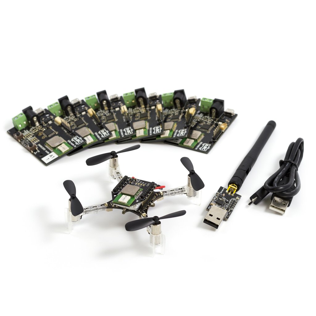
We decided to use the Loco positioning system as a base to be able to do scripted flight and chose Two Way Ranging to reduce the number of anchors needed. We used only four anchors arranged as a 3×3 m square, three of them on the floor and the fourth 1.5 meters up on a tripod. Two Way Ranging works very well outside of the convex hull (which is really small in this case) but with the drawback that we only could position one Crazyflie – no swarm show.
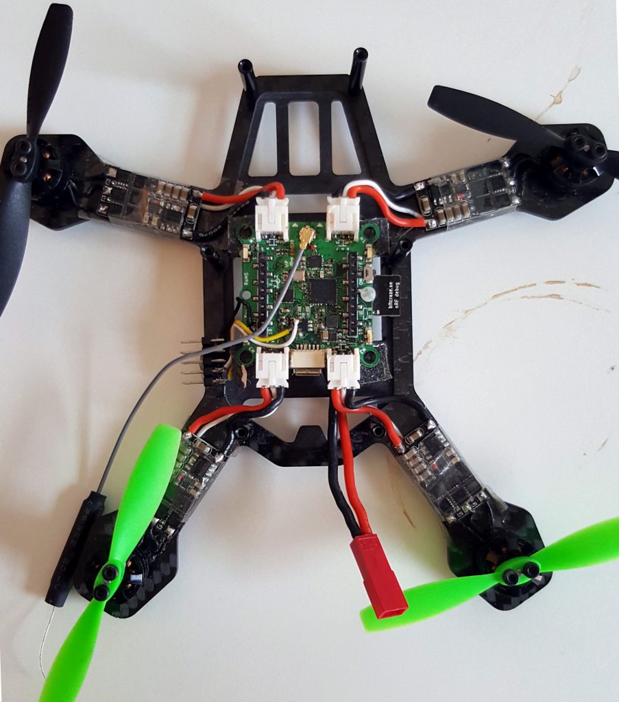
For the visibility we used a prototype deck with a high intensity LED pointing downwards.
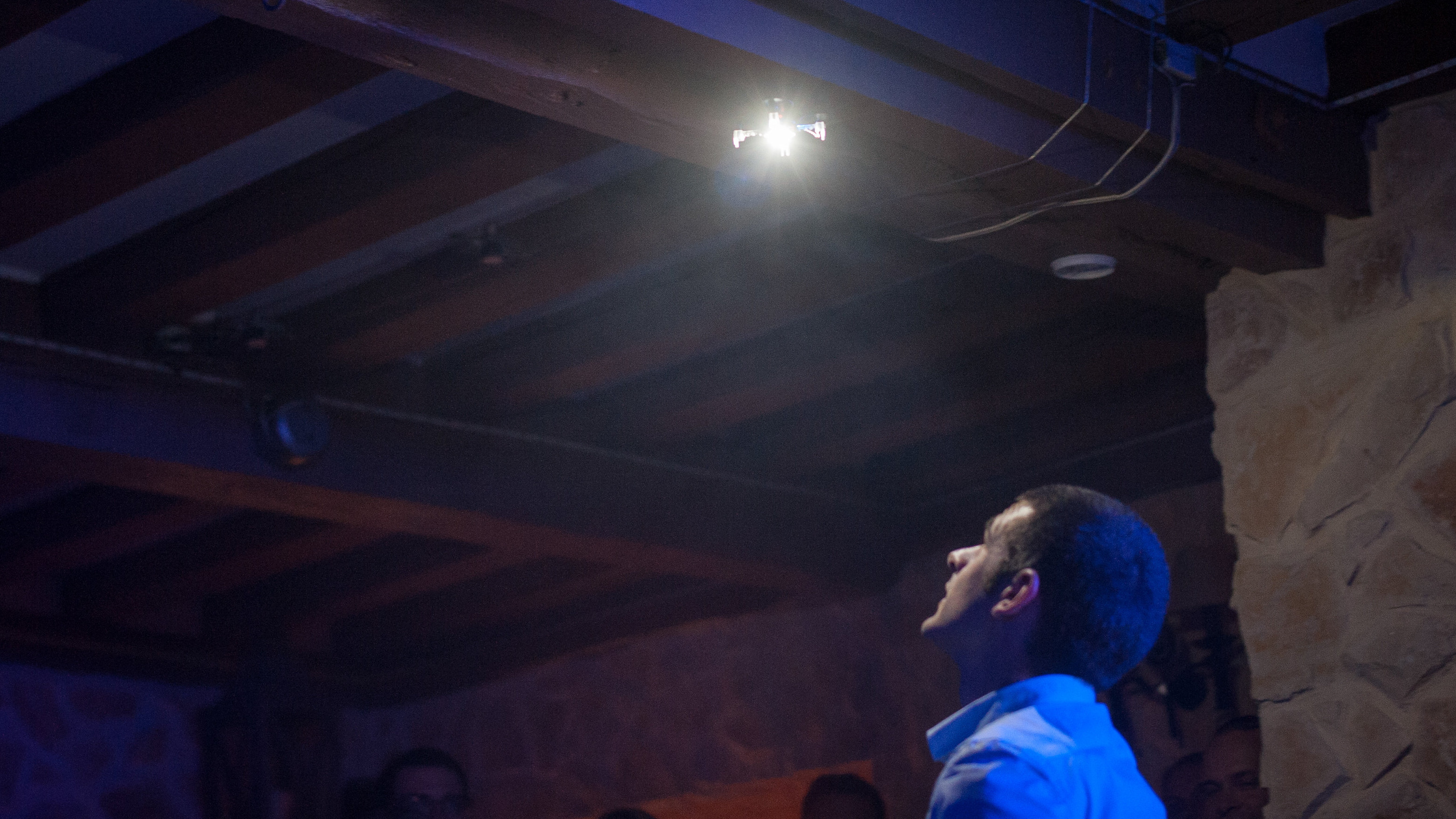
Photo by Eric Cunha
Again to minimize the equipment we decided to pre-program the sequence in the Crazyflie and put a start button on it to run the sequence. The piece of music to be used (composed by the groom during the bachelor party) was about one and a half minute long and the idea was to start the music and the sequence manually at exactly the same time and let them run without any further synchronisation.
We based our purpose built firmware on the demo code from ICRA earlier this year. It contained the sequencing but we had to add functionality to control the LED. We wrote a python script that generated data for the sequence that could be pasted into the firmware. A button was soldered on top of the Loco Positioning Deck and connected to a GPIO pin to be used as a start button.
We are engineers and not choreographers but after some trial and error we managed to create a sequence with light that was synchronized to the music. The overall idea was to start the Crazyflie on the floor in the center of the space, go out into the audience during the intro and turn on the light over Adrian (that was carefully positioned on the correct spot) and guide him onto the “stage”. While Adrien improvised acrobatics on the floor the Crazyflie circled around and above him with flashing lights. At the end of the music the procedure was reversed and the Crazyflie guided him back into the crowd and landed quietly in the center of the stage.
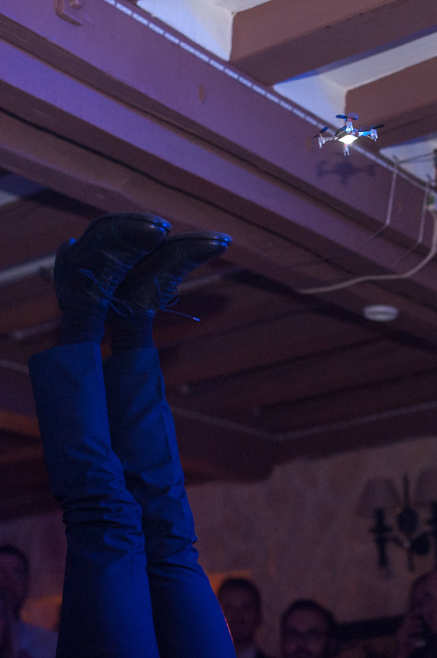
Photo by Eric Cunha
After dinner when it was time for the show we set up the positioning system and the crowd gathered. The first two attempts failed as it turned out that the ceiling of the venue was lower than expected and the Crazyflie hit a beam! What to do? We had a pre-programmed sequence that was going too high! We simply moved the anchors 30 cm away from each other and “stretched” the space to trick the Positioning system a bit. We had not tried this before and live hacking is a bit stressful, but we were possibly strengthened by one or two glasses of wine :-)
The third attempt was almost perfect with an incredible performance by Adrien! Phhuuu and what a success on the third attempt. Heart failure was close but did not kill us this time! :-) Maybe this is why we stay away from live shows and rather sitt down in a dark basement coding :-).