Continuing from last Monday post where the hardware wiring part was discussed we now move on to the software side. The brushed motors are controlled with a normal PWM where the duty cycle will adjust how much power goes into the motors. A brushless motor on the other hand needs more complicated controlling and uses it’s own micro-controller to handle this. These brushless motor controllers (BLMC or Brushless ESC) comes in many flavors and sizes but what is pretty common is how they are interfaced/controlled. This is inherited from how R/C receivers are controlling servos and how the receiver gets updates from the transmitter. This is a PWM where the width of the high pulse define the duty cycle. 1ms equals min and 2ms equals max and this is repeated every 20ms, thus giving an update rate of 50Hz.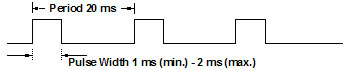
This way of interfacing the BLMC is currently the most common way but interfacing with I2C, CAN, etc is getting more common.
To generate the servo PWM on the Crazyflie we have just reconfigured the timer a bit using a conversion macro so that setting the motor ratio of zero will result in a 1ms high pulse and setting it to max (uint16) will result in a 2ms pulse. The period time can be set with the BLMC_PERIOD define in motors.h. The standard period time of 20ms is actually a big drawback as it adds a latency from when a new output is calculated to when it is actually set. Therefore many motor controllers allow to shrink this period down to 2.5ms (400Hz) which result in lower latency and better flight stability.
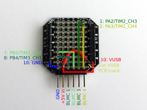
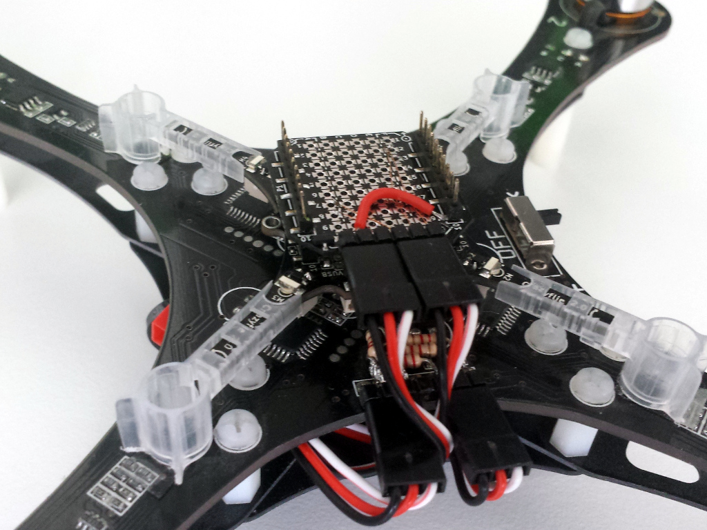
Brushless prototype board
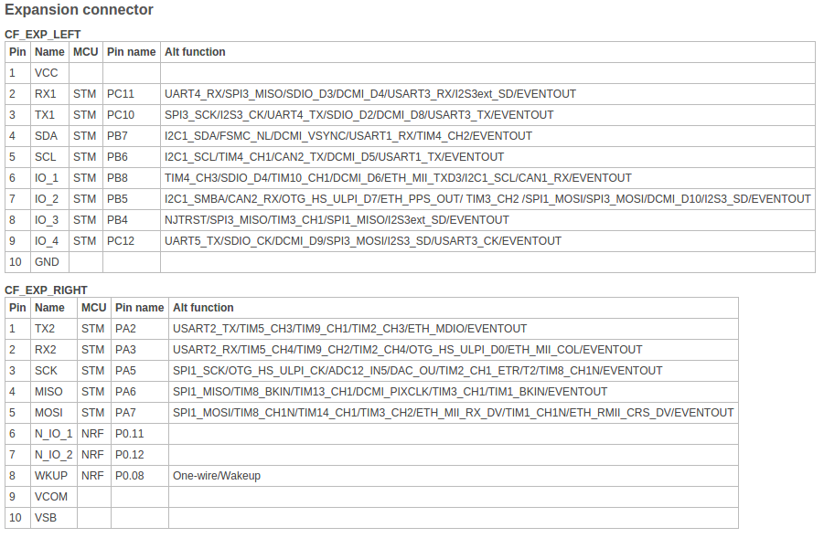
First you need to put together the brushless prototype board from the last post. The output will be generated on the pins marked BLMC 1,2,3,4 which should be connected in the same position an rotational direction as the brushed M1, M2, M3, M4 respectively. The output signal will be 0v – 3.0v which should work fine with 5V BLMC but it might be worth keeping that in mind.
Building the brushless firmware
The code which contains the brushless functionality is currently on the bigmerge branch so start by pulling the latest changes and switching to that branch.
git pull
git checkout bigmerge
Then to activate the brushless functionality enable the brushless defines
BRUSHLESS_MOTORCONTROLLER
BRUSHLESS_PROTO_DECK_MAPPING
This can be done by by either creating defines in config.h or by creating aconfig.mk file in the same directory as the Makefile with the content:
CFLAGS += -DBRUSHLESS_MOTORCONTROLLER
CFLAGS += -DBRUSHLESS_PROTO_DECK_MAPPING
The period time BLMC_PERIOD is by default set to 2.5ms (400Hz) so change that if needed.
Then build the firmware (make sure to clean first)
make clean
make
It will build for the Crazyflie 2.0 and for wireless bootloading by default. Put the Crazyflie 2.0 in bootloader mode by holding the power button until the blue led start to blink, then flash it with the wireless bootloader (Crazyradio required).
make cload
Causion!
You are now probably dealing with powerful and dangerous stuff so make sure to take precautions. E.g. don’t have propellers mounted when you test! When you have taken all the safety precautions do your first test. Remember the Crazyflie firmware has not yet been developed for big quads, it is all at your own risk! And another thing, even though the Crazyflie 2.0 can be controlled using a mobile device we don’t recommend this, use a Crazyradio.
Tuning
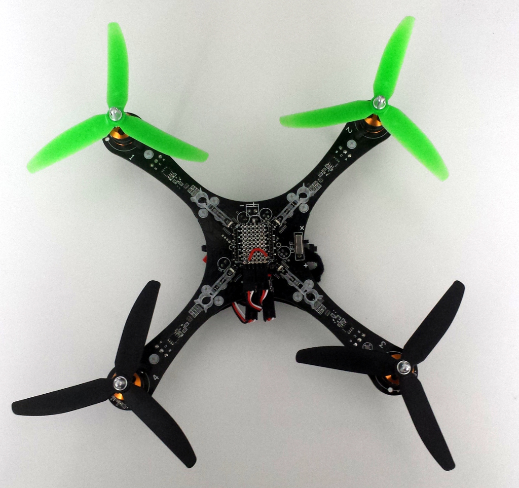
With that cautions being said it is great seeing a big quad fly and we will soon put out a video showing some of our builds. Our bigger quads have flown quite well with the stock tuning (PID parameters) but tuning should be done as well. Plenty of guides can be found on ways how to do it so I will not go into details here. The values can be found in pid.h and can be updated (but not saved) live using the cfclient. To save them the pid.h file must be changed and the firmware flashed again.


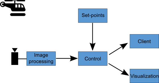


 We are planning some nice demos including autonomous flight with kinect2 and wireless computer controlled light effects using the LED-Ring so be sure to check us out!