This week we have a guest blog post by Ben, enjoy!
I’m Ben Kuperberg and i’m a digital artist, artist-friendly software developer and orchestra conductor. Being a juggler, I’ve decided to focus some of my work on the intersection between juggling and technology, and i’ve since been working more and more with jugglers, my last project being “Sphères Curieuses” from Le Cirque Inachevé, created by Antoine Clée. While the whole project is not focused on drones, a part of it involves synchronized flight of multiple drones and precise human interaction with those drones. Swarm flight is something already out there and some solutions already exist but the context of this project added some challenges to it.
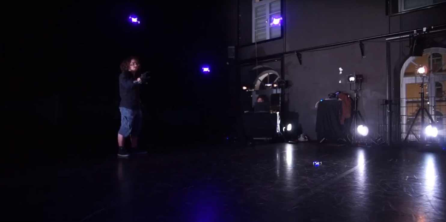
Most work on drone swarms have been done by research group or school. They use high-grade expensive motion-capture system able to track precisely the drones and able to assign their absolute positions. While the quality of the result is undeniable, it’s not fit for stage shows : the setup is taking a lot of time which we can’t always have when the show is on the road. Moreover, the mocap system is too invasive for the stage if you want to be able to “hide” a bit the technology and let the spectator focus on what the artist wants you to see. Not to mention it costs an arm and a leg and Antoine needs both to juggle.
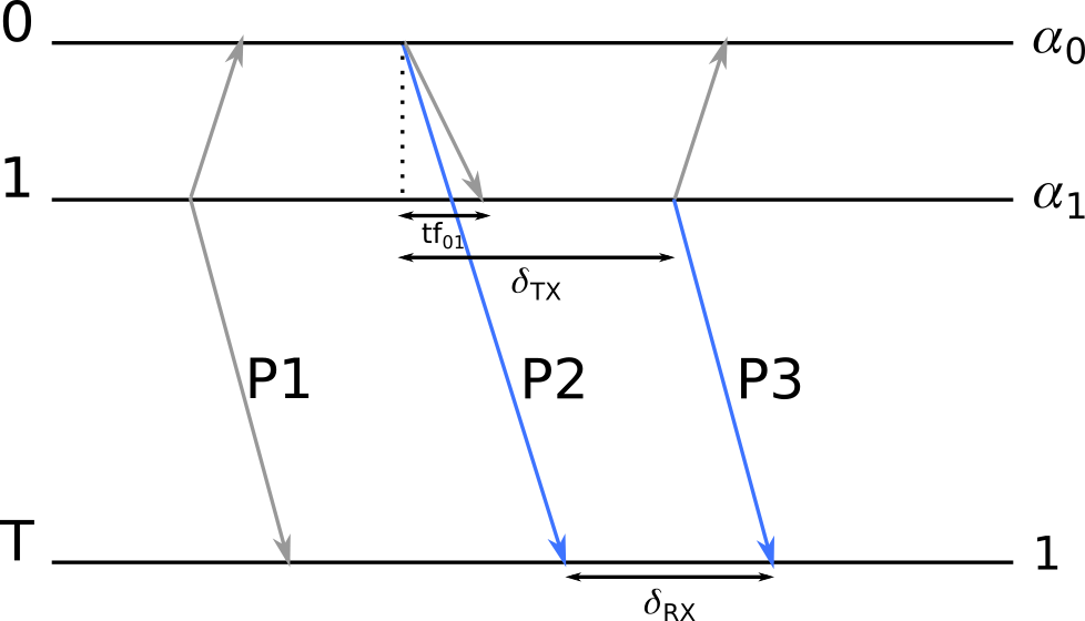
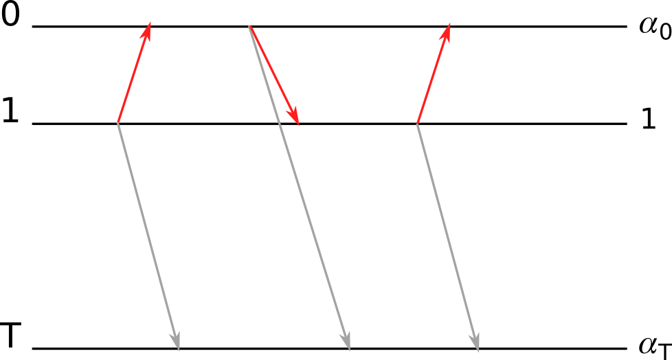
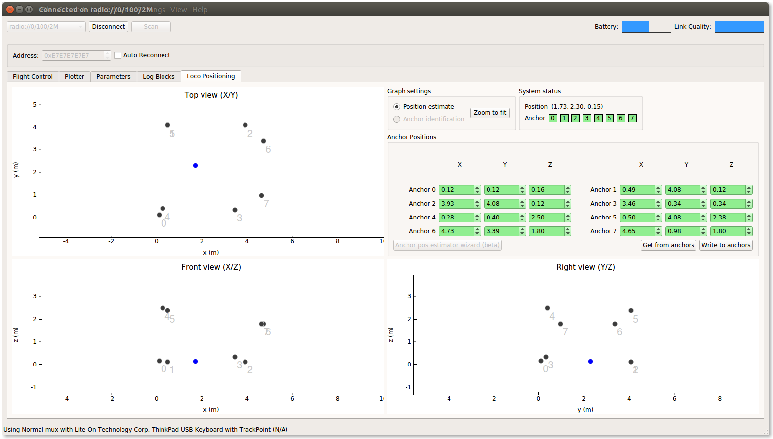
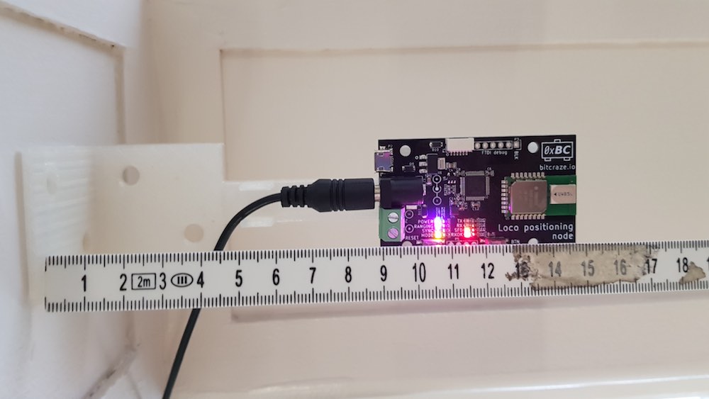
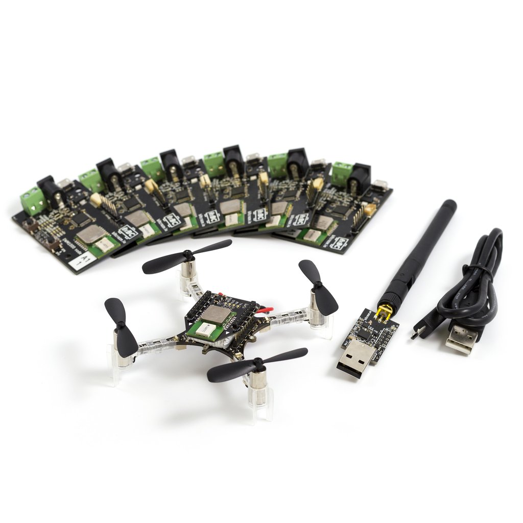
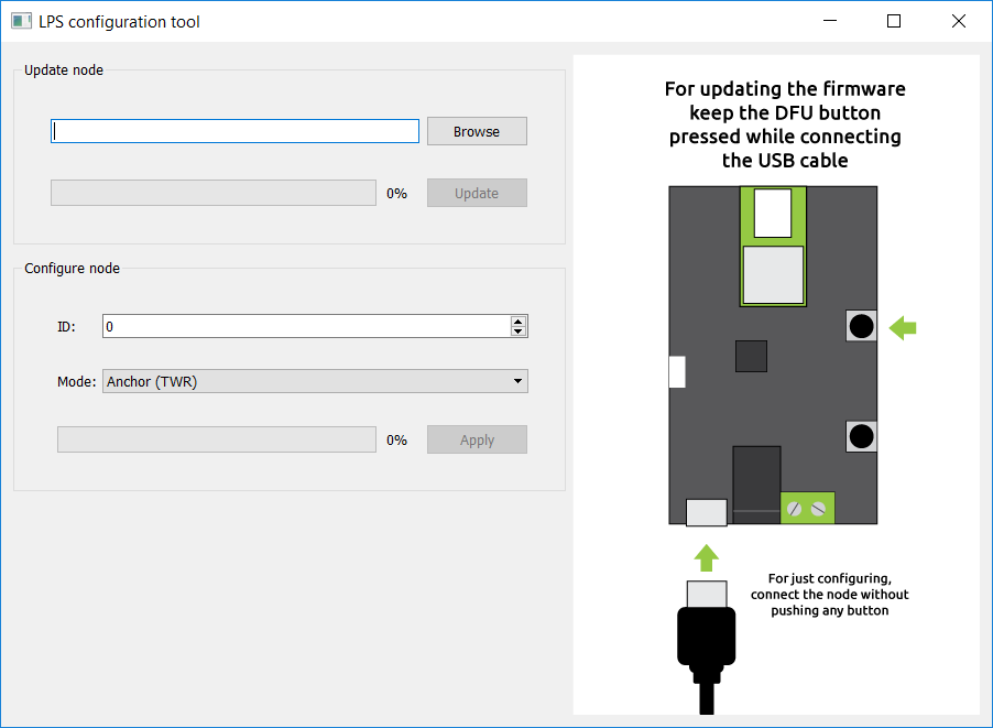
So we had to find other ways to be able to track multiple drones. That’s when we found out the [amazing] team at Bitcraze was working on the TDoA technology, which allows precise-enough tracking of a virtually unlimited amount drones, at reduced cost and with a fast and clean setup.
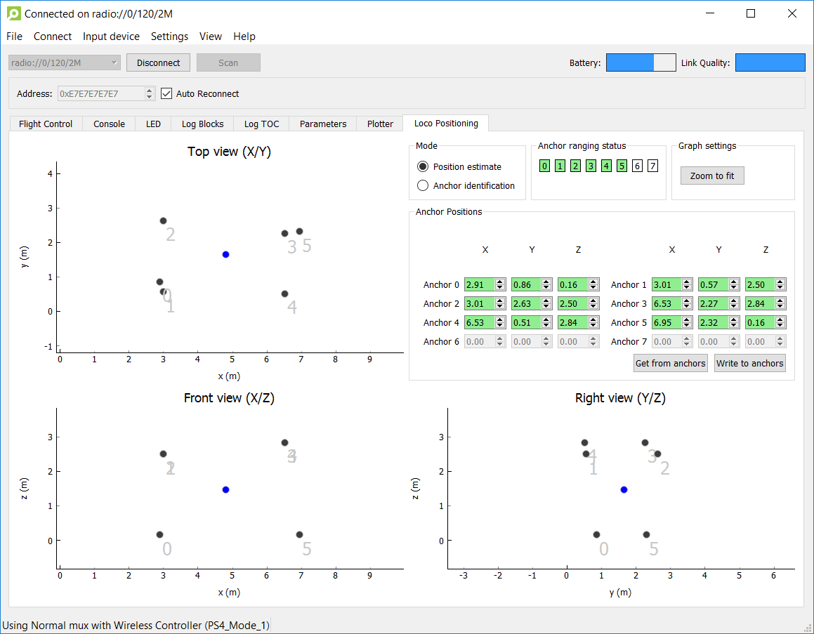
After some work we managed to have a first rough version of our swarm server made by Maxime Agor that allowed to connect and move multiple drones using the TDoA system, controlled from a Unity application.
While we were able to present a decent demo with this system, we were facing a major problem of reactivity. When working with artists and technology, reactivity is a key component to creativity. Because it can be frustrating and tense to stop each 2 minutes to make changes or fix problems. My first priority was therefore to prepare and design softwares that will allow me to spend most of the “creation time” on the actual creation aspect and not on technical parts. It is also essential that the artist performing in front of the audience can entirely focus on the performance and by fully confident in this technology. The last challenge is that as I focus my work on the creation and not touring, all my work needs to be easily understood and modified by both the artists and the technicians who will take over my work for the tour.
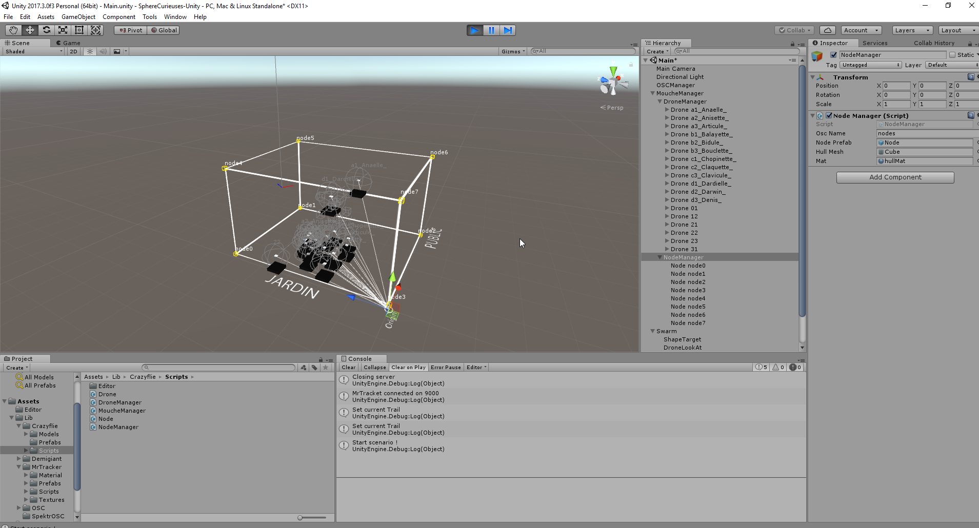
With all of that in mind, I decided to create a software with a high-end user interface called “La Mouche Folle” (« The Crazy Flie » in french) that allows to control multiple drones and have an overview of all the drones, their battery/charging/alert states, auto-connect / auto-reboot features, external control via OSC, and a Unity client to view and actually decide how to move the drones. All my work is open-source, so you can find the software on github.
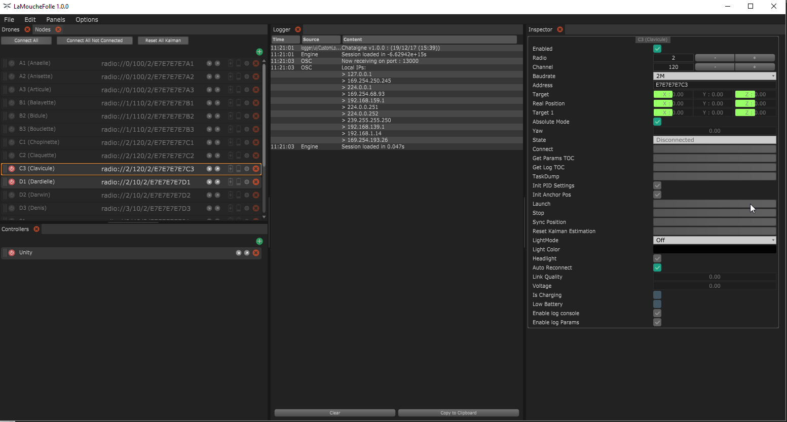
There only is a Windows release for now but it should compile just fine on OSX and Linux, the software is made with JUCE, depends on OrganicUI and lib-usb. Feel free to contact me if you want more information on the software. Many thanks Wolfgang Hoenig for the support and the great work on the crazyflie cpp library i’m relying on.
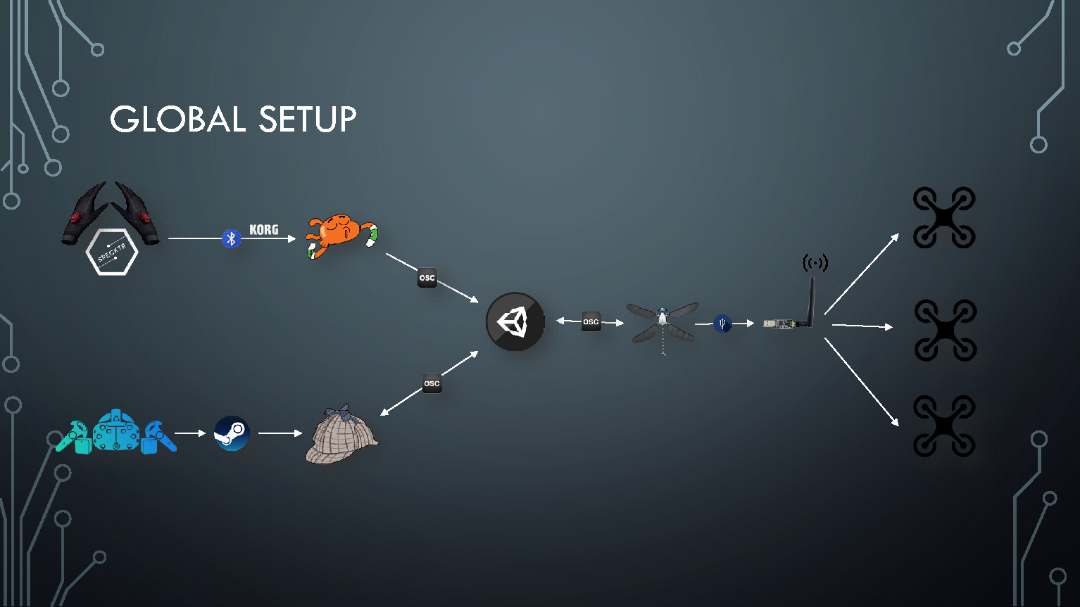
So this is the basic setup of our project, but we needed more than that to control the drone. We wanted to be able to control them in the most natural way possible. We quickly decided to go with glove-base solutions, and have been working with Specktr to get our hands – pun intended – on developer versions of the glove. The glove is good but can’t give us absolute position of the hand, so we added HTC Vive trackers with the lighthouse technology and then were able to get both natural hand control and sub-millimeter precision of the tracked hand.
Then it was a matter of connecting everything together : for other projects for Theoriz Studio, I already developed MrTracker (used in the MixedReality project) that acts as a middleware between the Vive trackers and Unity.
I used Chataigne to easily connect and route the Specktr Glove data to Unity as well so we would have maximum flexibility to switch hardware or technology without breaking whole setup if we needed to.
In the past years, i’ve come to work on a lot of different projects, with different teams, which i like very much, because each project leads to discover new people, new ways of working and new challenges to overcome. I’m having a great time working on this project and especially sharing everything with the guys at Bitcraze and the community, everyone has been so cool and nice. I’ve planned to go at the Bitcraze studios to work for few weeks with them and i’m sure it’ll be a great experience !