Guest post by Dominik Grzelak, Dresden University of Technology, Germany
In my initial post about XR-PALS, I introduced a tool on reducing setup time for the Loco Positioning System (LPS). Over time, one very practical aspect remained: handling and mounting the LPS nodes themselves.
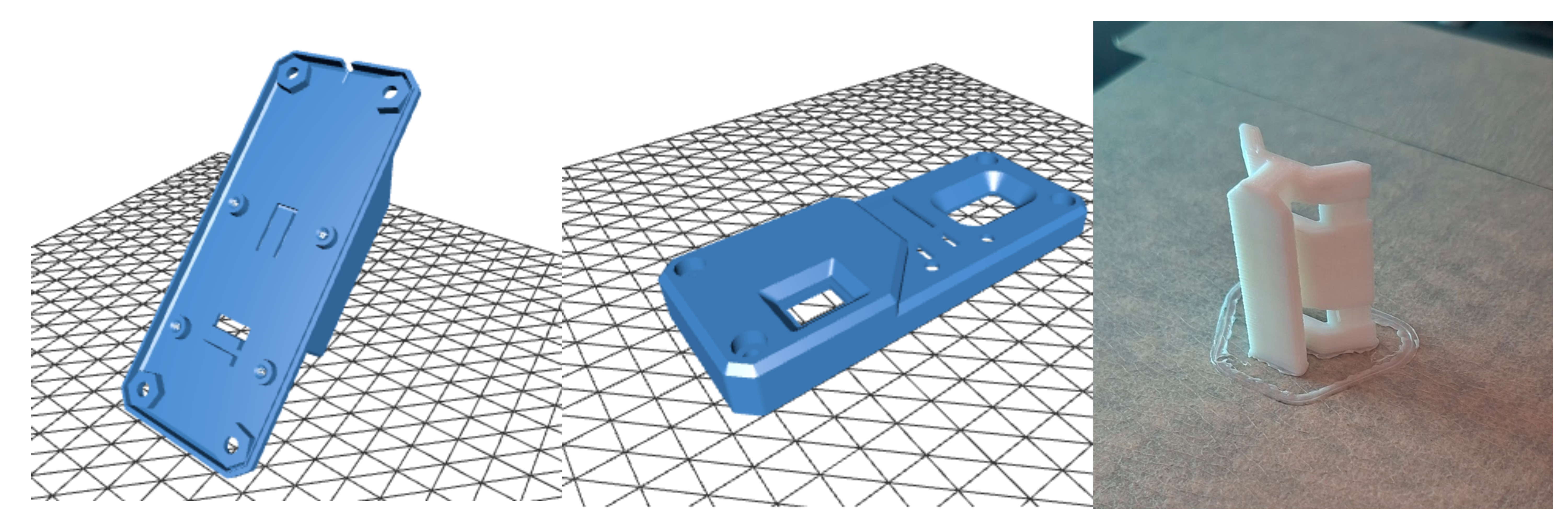
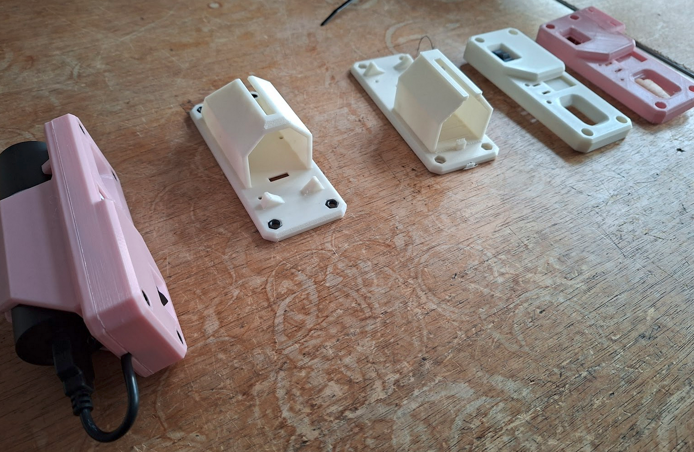
In this post, I would like to share a 3D-printable enclosure and mounting system for LPS nodes that emerged from daily use and was developed hand-in-hand with a technical designer friend. The goal was to make LPS nodes faster to deploy, and more robust in general; they have already withstood drops from heights of up to 2 m.
Place the back part as shown in the figure to print without supports. Rotate the front part by 180° relative to the figure to print without supports. The adapter should be printed standing upright.
Below are a few notes to get you started building the case:
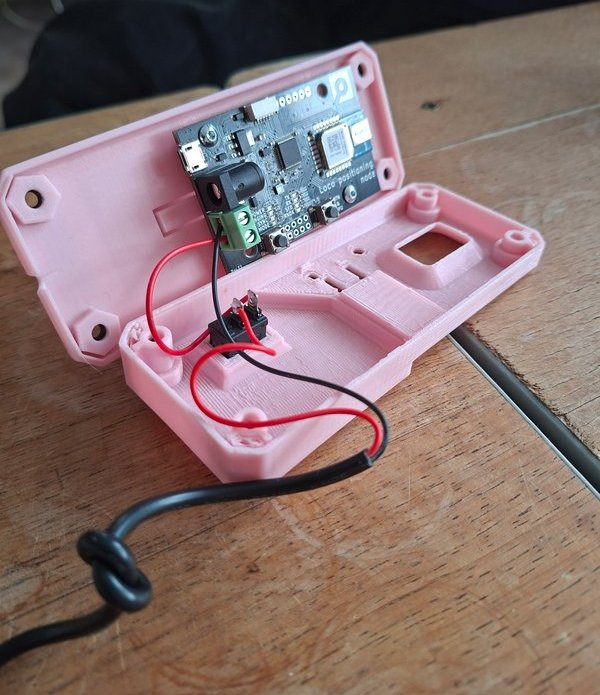
Place the LPS node into the back part of the case.
Install the toggle switch and ensure correct orientation.
Connect and solder the USB power cable wires.
Lay down the USB cable on top of the designated notch in the back part (tie a small knot to release the tension).
Attach the front part and secure it with screws.
Use the adapter (“slider”) to mount the case on a tripod or pole (with cable ties, for example).
Make sure the red and black cables are wired correctly.
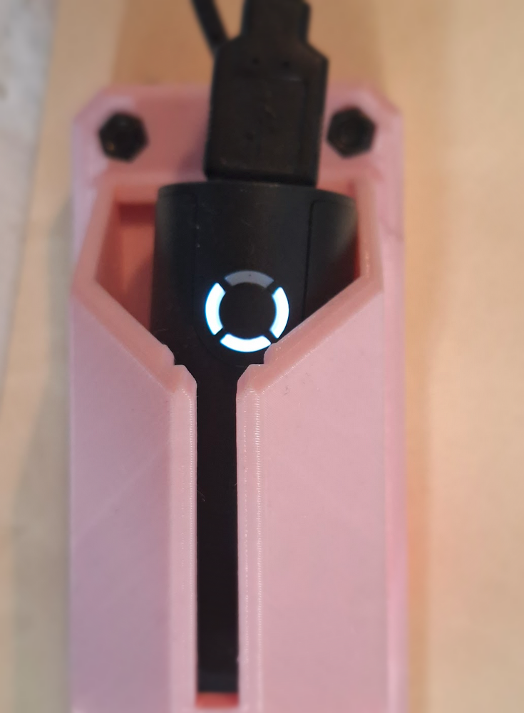
The USB power bank itself serves as the power indicatorfor the LPS node.
Evolution of the Case
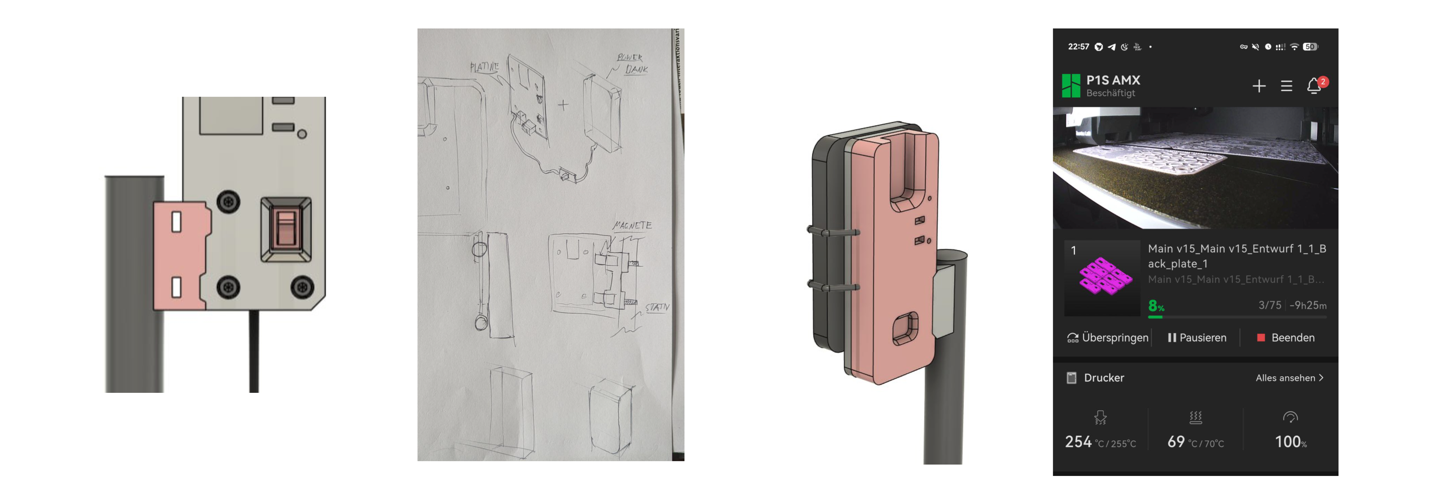
The design itself went through several iterations with adjustments.
In parallel, multiple design variations were explored to evaluate different approaches to mounting, cable routing, and overall form factor. Attention was paid to ensuring the parts print cleanly on common 3D printers without supports.
This process helped smooth out small usability issues and resulted in a design that is both easy to print and straightforward to use in practice.
Vertical and Horizontal Mount Adapter
While the standard configuration mounts the enclosure vertically, a horizontal holder adapter has now been introduced. This provides additional flexibility depending on the experimental setup.
A short demonstration of the mounting system can be viewed here.
Conclusion
This enclosure and mounting system grew out of repeated practical use in changing indoor environments, and we hope it will be useful to others as well.
Feedback and ideas are always welcome. And by the way, if you print your own version, feel free to share photos of your setup!
Swarm robotics has undergone rapid evolution and is now used in real-world applications. At the center of this exciting journey is the Crazyflie. Although small, its capabilities make it ideal for swarming applications in research, education, and prototyping.
Small and Safe for Indoor Use
The Crazyflie 2.1+ is a nano-quadcopter that weights only 29g. Crazyflie swarms are safe to interact with and can fly in confined spaces like labs or classrooms. If the maximum recommended payload of 15g is not enough for your application, the Crazyflie 2.1 Brushless is a suitable alternative, as it has a recommended payload of 40g. These two platforms are compatible, allowing them to cooperate within a mixed swarm of your preference.
Setting Up a Crazyflie Swarm
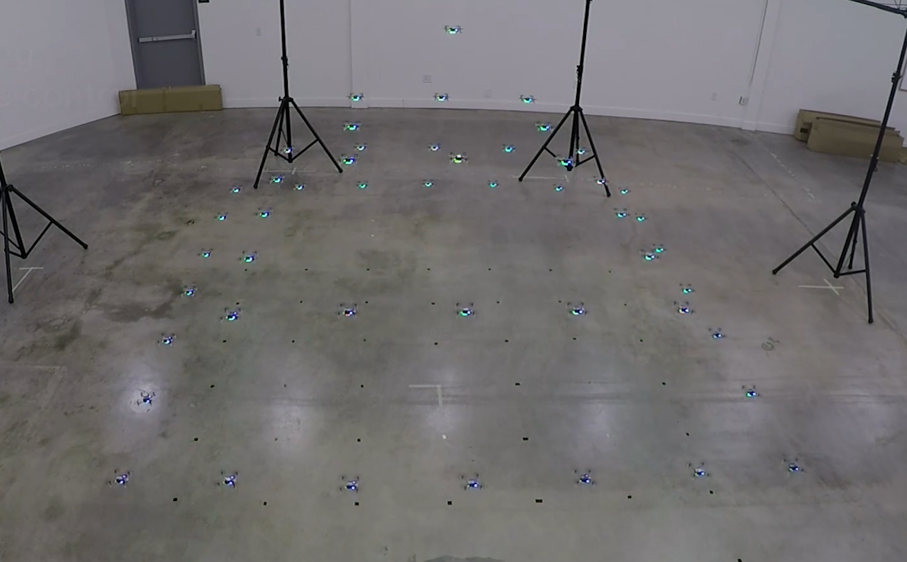
Transitioning from a single Crazyflie to a swarm setup requires certain adjustments. Depending on the amount of data that you want to transfer to and from your Crazyflies, you might need to use more Crazyradio 2.0 dongles. We recommend 3-4 Crazyflies per radio but under ideal conditions each one can handle up to 15 drones. To get the most out of your swarm, you will also need an external positioning system. This could be a Lighthouse positioning system, a Loco positioning system or a Motion Capture system. This allows each Crazyflie to know its absolute position in space. A very interesting swarming project is Crazyswarm where they managed to fly a swarm of 49 Crazyflies using 3 Crazyradios and different positioning systems.
The Crazyswarm project. You can find the full video here.
Available Swarming Frameworks and Examples
To make your introduction to a Crazyflie swarm smoother, our python library contains a swarm class. It allows the user to control each drone in the swarm simultaneously, sending commands either in parallel or sequentially. The library also includes examples that demonstrate the capabilities of a Crazyflie swarm. For users interested in exploring advanced decentralized swarm schemes, we support firmware that enables peer-to-peer communication. This is at an experimental level and has been used for the decentralized brushless swarm demo and for the ICRA 2025 demo.
Getting Started
Interested in building your first swarm? Explore our swarm bundles featuring multiple platforms and positioning systems that suit your research or development needs. If you are new to the Crazyflie ecosystem, make sure to follow the step-by-step swarm tutorial to better understand the setup process, communication flow, and control mechanisms involved in operating a drone swarm.
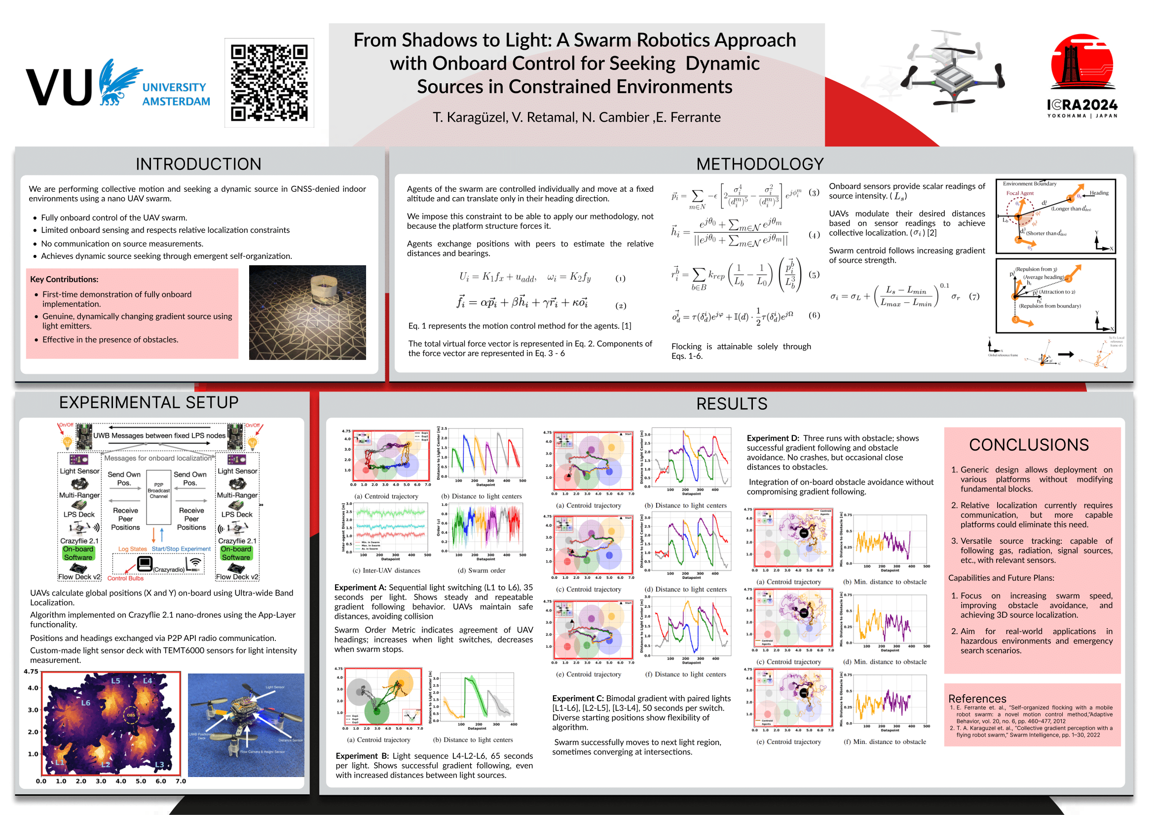
Today, we’re excited to share research from Vrije Universiteit Amsterdam, ‘From Shadows to Light,’ which presents an innovative swarm robotics approach where nano-drones autonomously track dynamic sources indoors.
Motivation
In dynamic and unpredictable indoor environments, locating moving sources—such as heat, gas, or light—presents unique challenges. GPS-denied settings, in particular, demand innovative and efficient onboard solutions for both control and sensing. Our research demonstrates how small drones, like Crazyflies, can be organized into a coordinated swarm to autonomously locate and follow these sources indoors, relying solely on onboard sensing and communication capabilities. Without sharing individual measurements, each drone adapts its behavior in response to its own sensor readings, allowing the swarm to collectively converge on the center of a light source through modified interactions with nearby agents.
Tugay Alperen (right) and Victor Retamal (left) during ICRA 2024 poster session
Method
Our approach enables each Crazyflie to function autonomously, using onboard sensing combined with continuous inter-agent communication at a frequency of 20 Hz. This methodology is structured around three core components:
Proximal Control and Collective Motion
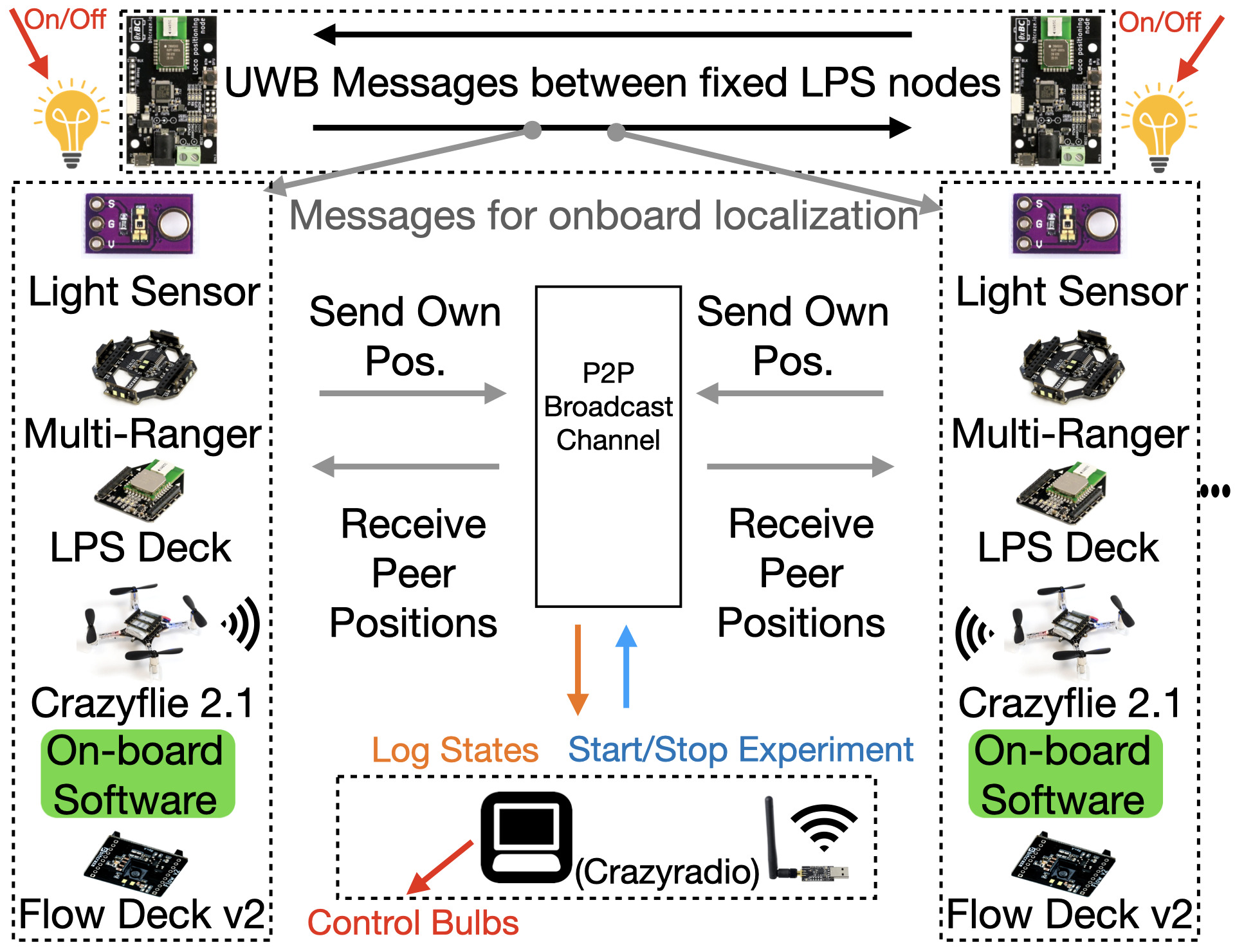
Each drone broadcasts its position to nearby agents, enabling the calculation of relative positions to maintain safe distances. This proximal control ensures cohesive group movement by computing virtual force vectors for velocity commands, which are sent to onboard controllers operating at 20 Hz.
Source Seeking Through Adaptive Social Proximity
Drones use custom light sensors to detect local light intensity. Instead of directly adjusting positions based on this measurement, each drone modifies its social proximity to neighbors according to the sensed intensity without broadcasting this information. This adaptation allows the swarm to collectively follow the light gradient toward the source in a decentralized manner.
Obstacle Avoidance
Equipped with time-of-flight sensors, each drone independently detects obstacles and adjusts its trajectory to maintain safety. This ensures the swarm remains intact while navigating toward the source.
By combining continuous relative positioning, virtual force-based control, individual sensing, and adaptive social behavior, our methodology provides a robust framework for efficient source seeking in GPS-denied indoor environments.
Experimental Setup
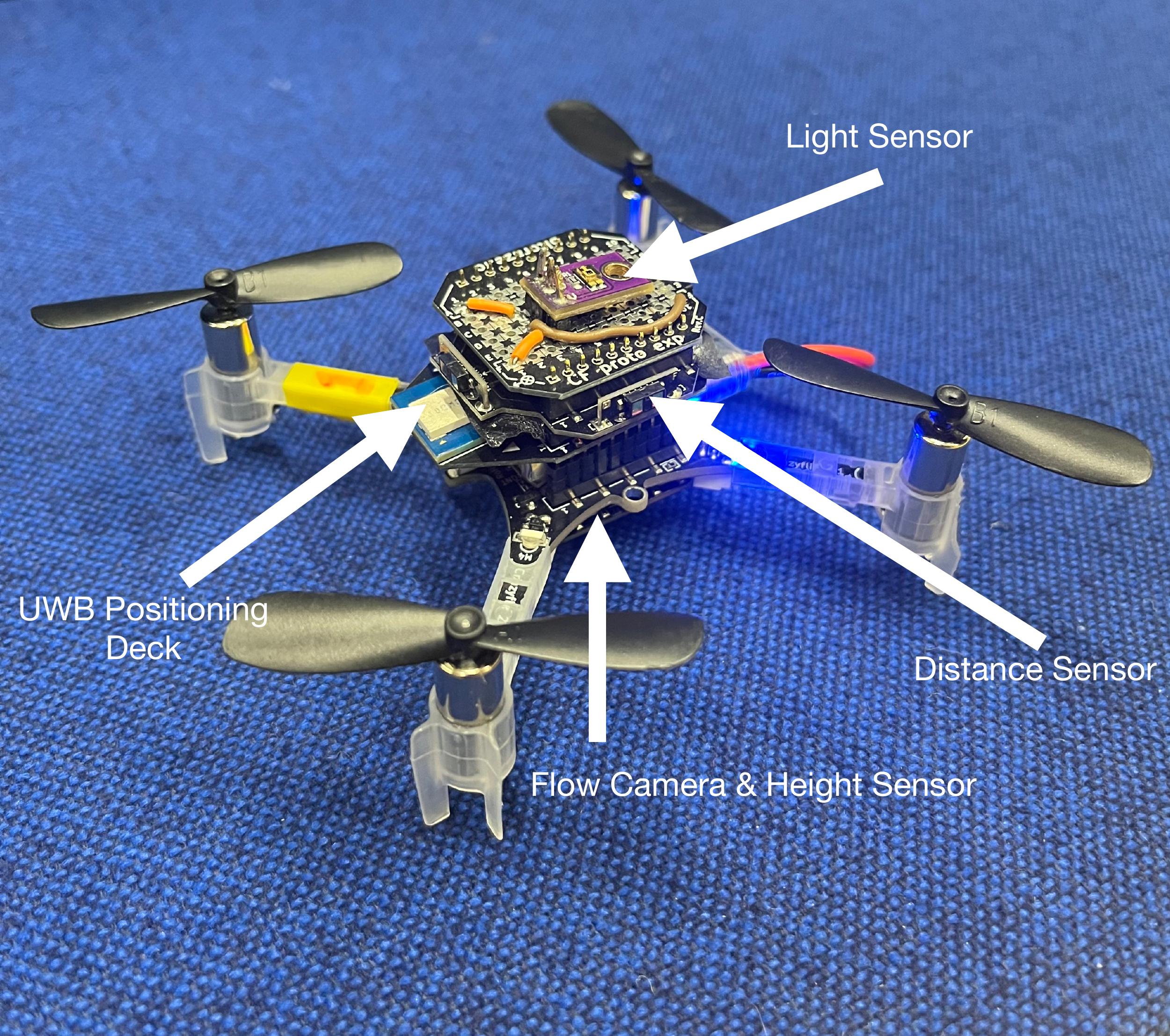
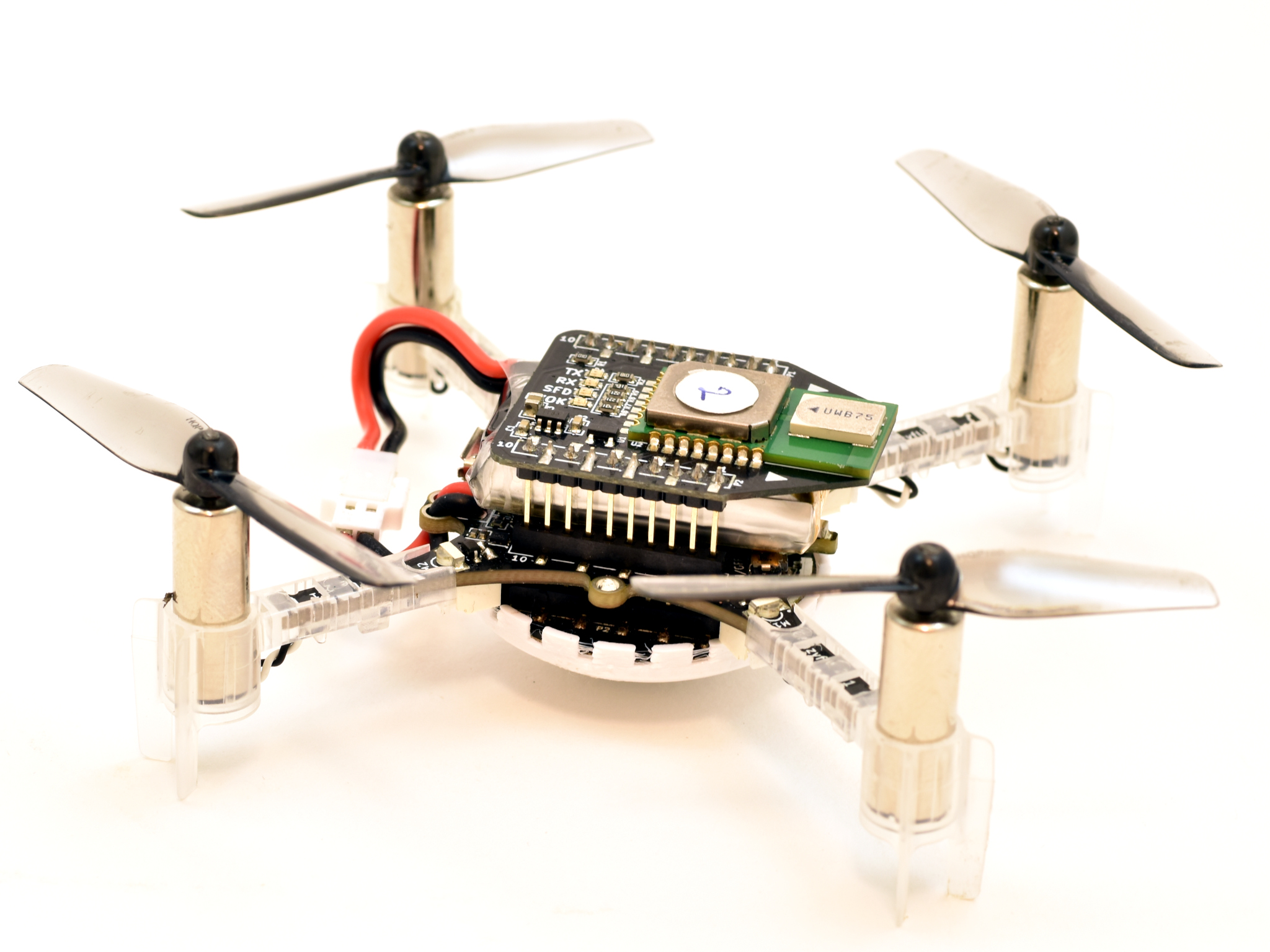
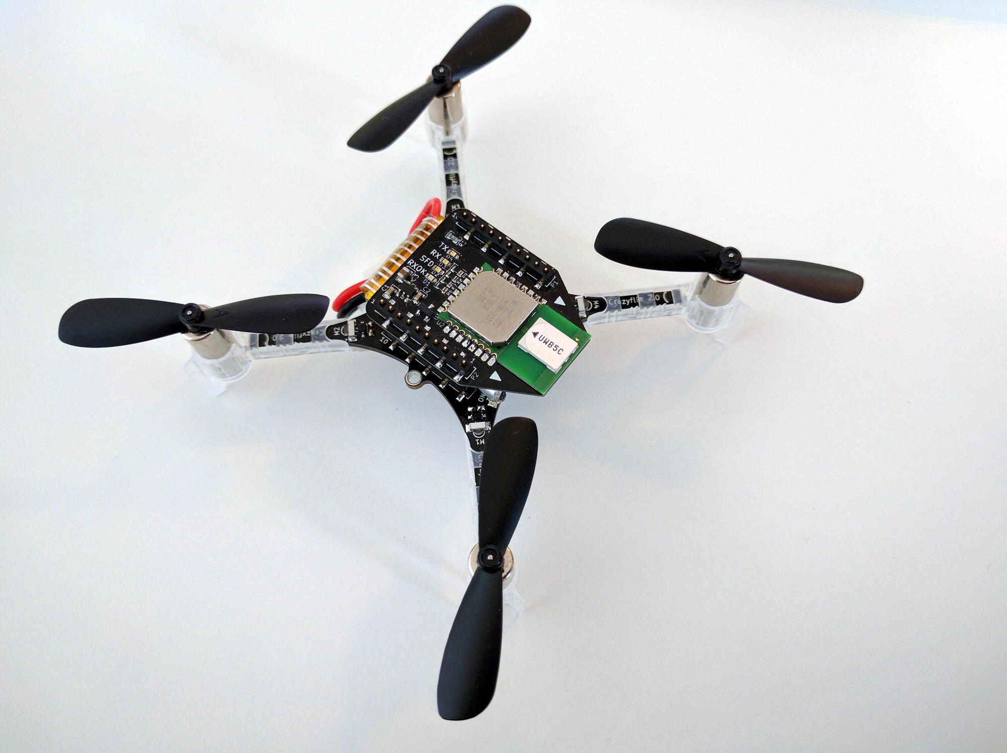
Crazyflie equipped with Flow Deck v2, UWB Deck, Multi-Ranger Deck, and a custom-made deck that produces an analog voltage reading from an LDR for light intensity measurements.
The system architecture allowing us to achieve autonomous flocking and source localization with a swarm of Crazyflie
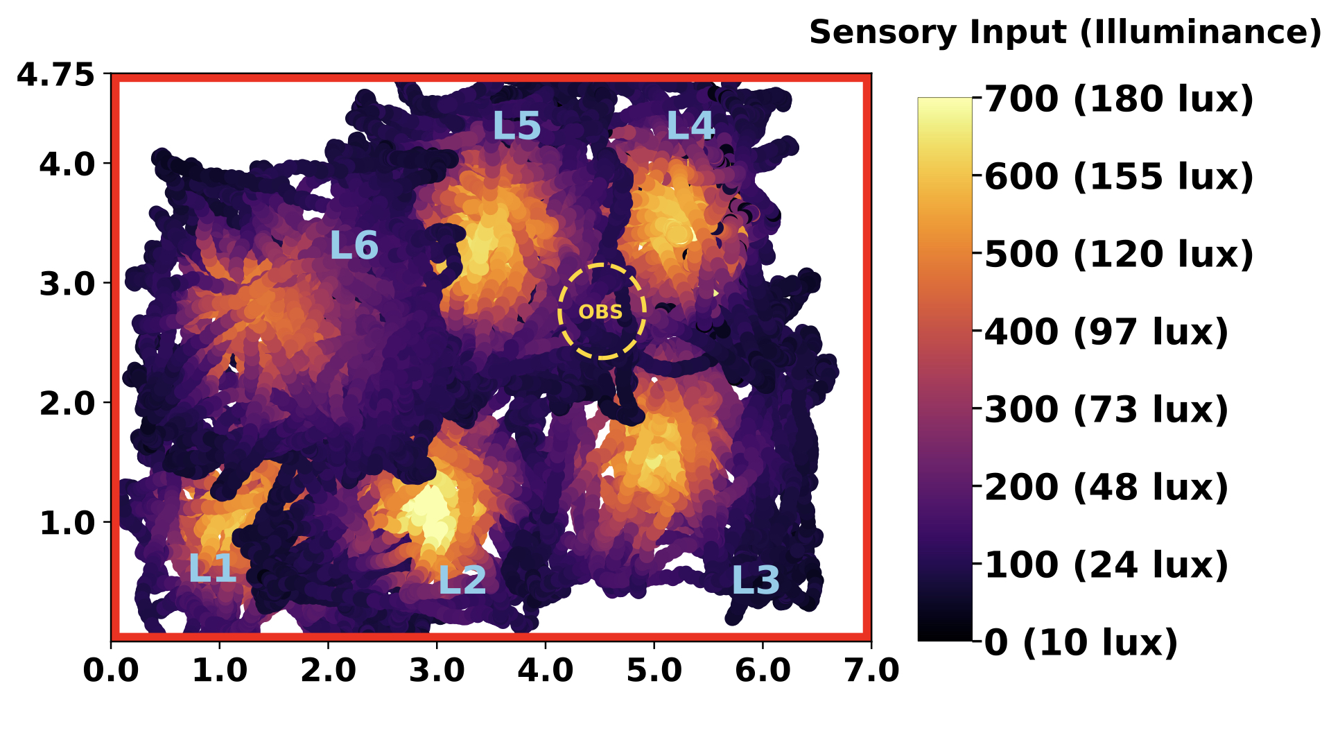
Our experiments take place in a 7×4.75-meter indoor arena with remotely controlled overhead light bulbs. These bulbs, activated individually or in pairs, create a moving light gradient. We tested our flocking swarm by initially positioning them at the edge of an illuminated area. As the light source shifted, we assessed the swarm’s performance by comparing their trajectories with the known centers of the illuminated areas without waiting for full convergence at each step. We also mapped our environment’s light intensity by moving a single Crazyflie randomly around the flight arena and recording the measurements to later merge on a single map to generate this light intensity heatmap.
The brightness values around the test environments, measured for each light source when only it was active.
Results
The flock flies as an ordered swarm, successfully localizing around the source with the swarm’s centroid positioned at the source center. (The centroid appears as a point without an arrow in the video.)
Even with an obstacle present within or between the illuminated regions, the flock successfully localizes around the center, avoiding the obstacle and maintaining order and cohesion within the swarm. The Multi-Ranger deck provides distance measurements for obstacle detection.
Future Directions
As the next step, we plan to apply our highly generalizable algorithm to various source types, including gas sources, radio signals, and similar sources that provide only scalar strength measurements rather than directional cues. Additionally, we have demonstrated that our flocking and source localization algorithms work effectively in 3D. We aim to showcase a fully functional application with a 3D-localized source and a flocking swarm operating in 3D space. Finally, we are working toward achieving fully onboard relative localization, which would eliminate the need for any indoor positioning system. This advancement would allow our swarm to operate autonomously in any environment, replicating the same behavior wherever it is deployed.
The authors were with the Vrije Universiteit Amsterdam.
Please feel free to contact us with any questions or ideas: t.a.karaguzel@vu.nl
Please cite this as:
@ARTICLE{10314746,
  author={Karagüzel, Tugay Alperen and Retamal, Victor and Cambier, Nicolas and Ferrante, Eliseo},
  journal={IEEE Robotics and Automation Letters},
  title={From Shadows to Light: A Swarm Robotics Approach With Onboard Control for Seeking Dynamic Sources in Constrained Environments},
  year={2024},
  volume={9},
  number={1},
  pages={127-134},
  keywords={Robot sensing systems;Autonomous aerial vehicles;Position measurement;Vehicle dynamics;Sensors;Location awareness;Drones;Swarm robotics;aerial systems: perception and autonomy;multi-robot systems},
  doi={10.1109/LRA.2023.3331897}}
When we originally wrote the TDoA3 implementation for the Loco Positioning System back in 2017 we had the idea of adding functionality to also enable the Crazyflies to send UWB packets in some situations, AKA TDoA3 Hybrid mode. We did not have the time to implement that idea back then, but through the years there have been some interest in the functionality and recently I finally got around to do it as a Fun Friday project. Annoying enough it was not that complicated and only took a couple of hours, I should have done it earlier!
We wrote a bit about the hybrid mode in an earlier blog post and there is also a github issue with some discussions on the topic. The short version of the functionality is that a Crazyflie at selected times switches from only passively receiving UWB packets from the anchors, to also actively transmitting packets and doing Two Way Ranging (TWR) with the peers in the network.
One use case is for a Crazyflie to simply participate in the TWR traffic to give it ranging information for improved position estimation. This can for instance be useful when flying outside the convex hull where TDoA positioning degrades rapidly while TWR works pretty well.
Another funky use case is to extend a Loco positioning system by using TWR to fly outside the convex hull and land somewhere. At this point the Crazyflie switches role and acts as an anchor instead by including its position in the transmitted packets and enabling other Crazyflies to use the transmissions for TDoA or TWR position estimation.
It is also possible to go even more dynamic and transmit the estimated position while flying and thus act as a flying anchor. There are complications when doing this with multiple Crazyflies as they use information from each other and the estimated positions probably will diverge if errors are not handled in a proper way, but at least there is now a framework where this type of functionality could be added. See the references to research in the area in the previous blog post.
The implementation is very experimental and has not been merged to master yet, but if you are interested you can find it in the krichardsson/hybrid-mode branch (PR #1330). There are a few new parameters that changes the behavior such as turning on/off transmissions, using TDoA or TWR data for position estimation and what to include in transmitted packets. Please see the implementation and documentation for details. Also note that the hybrid mode functionality is not compiled by default and must be enabled in the build configuration to be available.
In this blog post we will take a look at the new Loco positioning TDoA outlier filter, but first a couple of announcements.
Announcements
Crazyradio PA out of stock
Some of you may have noticed that there are a lot bundles out of stock in our store, the reason is the transition from Crazyradio PA to the new Crazyradio 2.0. Most bundles contain a radio and even though the production of the new Crazyradio 2.0 is in progress, the demand for the old Crazyradio PA was a bit higher than anticipated and we ran out too early. Sorry about that! We don’t have a final delivery date for the Crazyradio 2.0 yet, but our best guess at this time is that it will be available in about 4 weeks.
Developer meeting
The next developer meeting is on Wednesday, April 5 15:00 CEST, the topic will be the Loco positioning system. We’ll start out with around 30 minutes about the Loco Positioning system, split into a presentation and Q&A. If you have any specific Loco topics/questions you want us to talk about in the presentation, please let us know in the discussions link above.
The second 30 minutes of the meeting with be for general support questions (not only the Loco system).
The outlier filter
When we did The Big Loco Test Show in December, we found some issues with the TDoA outlier filter and had to do a bit of emergency fixing to get the show off the ground. We have now analyzed the data and implemented a new outlier filter which we will try to describe in the following sections.
Why outlier rejection
In the Loco System, there are a fair amount of packets that are corrupt in one way or the other, and that should not be part of the position estimation process. There are a number of reasons for errors, including packet collisions, interference from other radio systems, reflections, obstacles and more. There are several levels of protection in the path from when an Ultra Wide Band packet is received in the Loco Deck radio to the state estimator, that aims at removing bad packets. It works in many cases, but a few bad measurements still get all the way through to the estimator, and the TDoA outlier filter is the last protection. The result of an outlier getting all the way through to the estimator is usually a “jump” in the estimated position, and in worst case a flip or crash. Obviously we want to catch as many outliers as possible to get a good and reliable position estimate and smooth flight.
The problem(s)
The general problem of outlier rejection is to decide what is a “good” measurement and what is an outlier. The good data is passed on to the state estimator to be used for estimating the current position, while the outliers are discarded. To decide if a measurement is good or an outlier, it can be compared to the current position, if it is “too far away” it is probably an outlier and is rejected. The major complication is that the only knowledge we have about the current position is the estimated position from the state estimator. If we let outliers through, the estimated position will be distorted and we may reject good data in the future. On the other hand if we are too restrictive, we may discard “good” measurements which can lead to the estimator loosing tracking and the estimated position drift away (due to noise in other sensors). It is a fine balance as we use the estimated position to determine the quality of a measurement, at the same time as the output of the filter affects the estimated position.
Another group of parameters to take into account is related to the system the Crazyflie and Loco deck are used in. The over all packet rate in a TDoA3 system is changed dynamically by the anchors, the Crazyflie may be located in a place where some anchors are hidden, or the system may use the Long Range mode that uses a lower packet rate. All these factors change the packet rate and his means that the outlier filter should not make assumptions about the system packet rate. Other factors that depend on the system is the physical layout and size, as well as the noise level in the measurements, and this must be handled by the outlier filter.
In a TDoA system, the packet rate is around 400 packets/s which also puts a requirement on resource usage. Each packet will be examined by the outlier filter, why it should be fairly light weight when it comes to computations.
Finally there are also some extra requirements, apart from stable tracking, that are “nice to have”. As a user you probably expect the Crazyflie to find its position if you put it somewhere on the ground, without having to tell the system the approximate position, that is a basic discovery functionality. Similarly if the system looses position tracking, you might expect it to recover as soon as possible, making it more robust.
The solution
The new TDoA outlier filter is implemented in outlierFilterTdoa.c. It is only around 100 lines of code, so it is not that complex. The general idea is that the filter can open and close dynamically, when open all measurements are passed on to the estimator to let it find the position and converge. Later, when the position has stabilized, the filter closes down and only lets “good” measurements through. In theory this level of functionality should be be enough, after the estimator has converged it should never lose tracking as long as it is fed good data. The real world is more complex, and there is also a feature that can open the filter up again if it looks like the estimator is diverging.
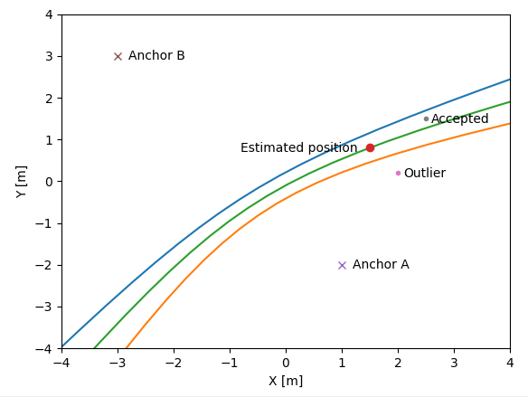
The first test in the filter is to check that the TDoA value (the measurement) is smaller than the distance between the two anchors involved in the measurement. Remember that the measurements we get in a TDoA system is the difference in distance to two anchors, not the actual distance. A measurement that is larger than the distance between the anchors is not physically possible and we can be sure that the measurement is bad and it is discarded.
The second stage is to examine the error, where the error is defined as the difference between the measured TDoA value and the TDoA value at our estimated position.
float error = measurement - predicted;
This error does not really tell us how far away from the estimated position the measurement is, but it turns out to be good enough. The error is compared to an accepted distance, and is considered good if it is smaller than the accepted distance.
sampleIsGood = (fabsf(error) < acceptedDistance);
The area between the blue and orange lines represents the positions where the error is smaller than some fixed value.
The rest of the code is related to opening and closing the filter. This mechanism is based on an integrator where the time since the last received measurement is added when the error is smaller than a certain level (integratorTriggerDistance), and remove if larger. If the value of the integrator is large, the filter closes, and if it is smaller than a threshold it opens up. This mechanism implements a hysteresis that is independent on the received packet rate.
The acceptedDistance and integratorTriggerDistance are based on the standard deviation of the measurement that is used by the kalman estimator. The idea is that they are based on the noise level of the measurements.
Feedback
The filter has been tested in our flight lab and on data recorded during The Big Loco Test Show. The real world is complex though and it is hard for us to predict the behavior in situations we have note seen. Please let us know if you run into any problems!
The new outlier filter was pushed after the 2023.02 release and is currently only available on the master branch in github (by default). You have to compile from source if you want to try it out. If no alarming problems surface, it will be the the default filter in the next release.
This year, the traditional Christmas video was overtaken by a big project that we had at the end of November: creating a test show with the help of CollMot.
First, a little context: CollMot is a show company based in Hungary that we’ve partnered with on a regular basis, having brainstorms about show drones and discussing possibilities for indoor drones shows in general. They developed Skybrush, an open- source software for controlling swarms. We have wanted to work with them for a long time.
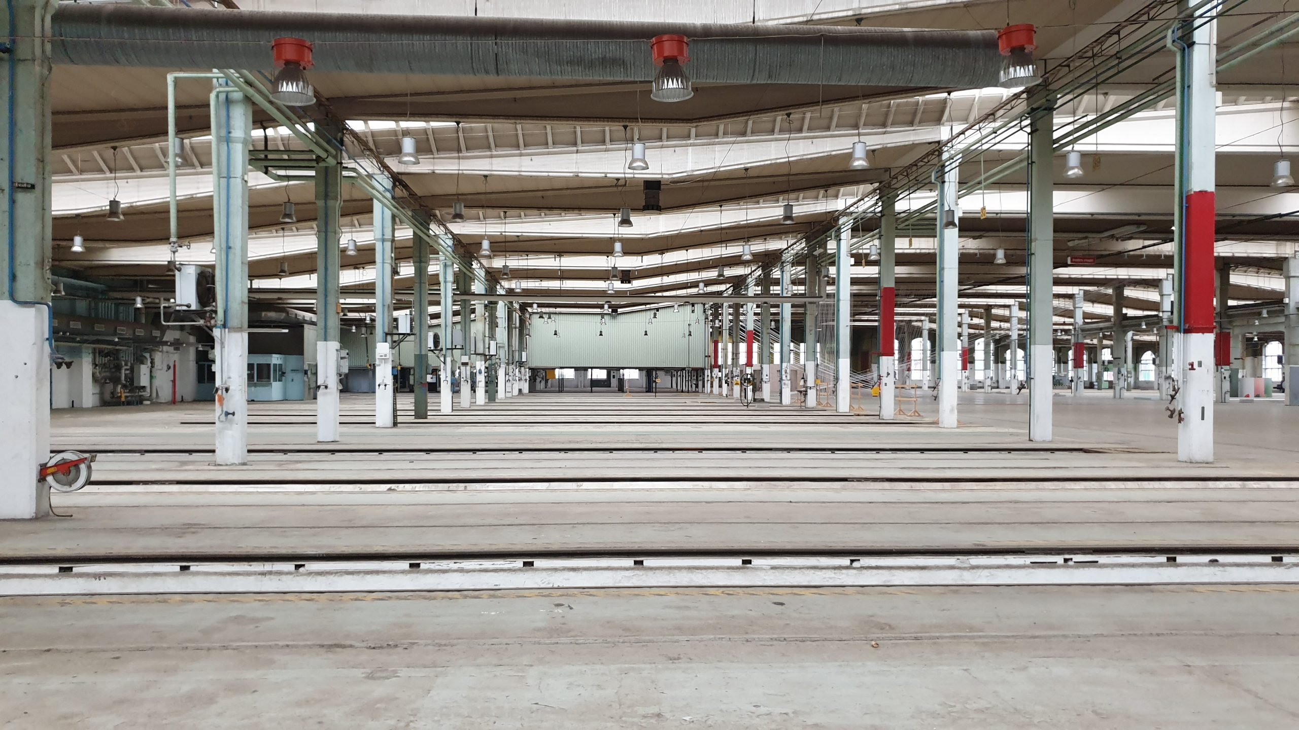
So, when the opportunity came to rent an old train hall that we visit often (because it’s right next to our office and hosts good street food), we jumped on it. The place itself is huge, with massive pillars, pits for train maintenance, high ceiling with metal beams and a really funky industrial look. The idea was to do a technology test and try out if we could scale up the Loco positioning system to a larger space. This was also the perfect time to invite the guys at CollMot for some exploring and hacking.
The train hall
The Loco system
We added the TDoA3 Long Range mode recently and we had done experiments in our test-lab that indicate that the Loco Positioning systems should work in a bigger space with up to 20 anchors, but we had not actually tested it in a larger space.
The maximum radio range between anchors is probably up to around 40 meters in the Long Range mode, but we decided to set up a system that was only around 25×25 meters, with 9 anchors in the ceiling and 9 anchors on the floor placed in 3 by 3 matrices. The reason we did not go bigger is that the height of the space is around 7-8 meters and we did not want to end up with a system that is too wide in relation to the height, this would reduce Z accuracy. This setup gave us 4 cells of 12x12x7 meters which should be OK.
Finding a solution to get the anchors up to the 8 meters ceiling – and getting them down easily was also a headscratcher, but with some ingenuity (and meat hooks!) we managed to create a system. We only had the hall for 2 days before filming at night, and setting up the anchors on the ceiling took a big chunk out of the first day.
Drone hardware
We used 20 Crazyflie 2.1 equipped with the Loco deck, LED-rings, thrust upgrade kit and tattu 350 mAh batteries. We soldered the pin-headers to the Loco decks for better rigidity but also because it adds a bit more “height-adjust-ability” for the 350 mAh battery which is a bit thicker then the stock battery. To make the LED-ring more visible from the sides we created a diffuser that we 3D-printed in white PLA. The full assembly weighed in at 41 grams. With the LED-ring lit up almost all of the time we concluded that the show-flight should not be longer than 3-4 minutes (with some flight time margin).
The show
CollMot, on their end, designed the whole show using Skyscript and Skybrush Studio. The aim was to have relatively simple and easily changeable formations to be able to test a lot of different things, like the large area, speed, or synchronicity. They joined us on the second day to implement the choreography, and share their knowledge about drone shows.
We got some time afterwards to discuss a lot of things, and enjoy some nice beers and dinner after a job well done. We even had time on the third day, before dismantling everything, to experiment a lot more in this huge space and got some interesting data.
What did we learn?
Initially we had problems with positioning, we got outliers and lost tracking sometimes. Finally we managed to trace the problems to the outlier filter. The filter was written a long time ago and the current implementation was optimized for 8 anchors in a smaller space, which did not really work in this setup. After some tweaking the problem was solved, but we need to improve the filter for generic support of different system setups in the future.
Another problem that was observed is that the Z-estimate tends to get an offset that “sticks” and it is not corrected over time. We do not really understand this and will require more investigations.
The outlier filer was the only major problem that we had to solve, otherwise the Loco system mainly performed as expected and we are very happy with the result! The changes in the firmware is available in this, slightly hackish branch.
We also spent some time testing maximum velocities. For the horizontal velocities the Crazyflies started loosing positioning over 3 m/s. They could probably go much faster but the outlier filter started having problems at higher speeds. Also the overshoot became larger the faster we flew which most likely could be solved with better controller tuning. For the vertical velocity 3 m/s was also the maximum, limited by the deceleration when coming downwards. Some improvements can be made here.
Conclusion is that many things works really well but there are still some optimizations and improvements that could be made to make it even more robust and accurate.
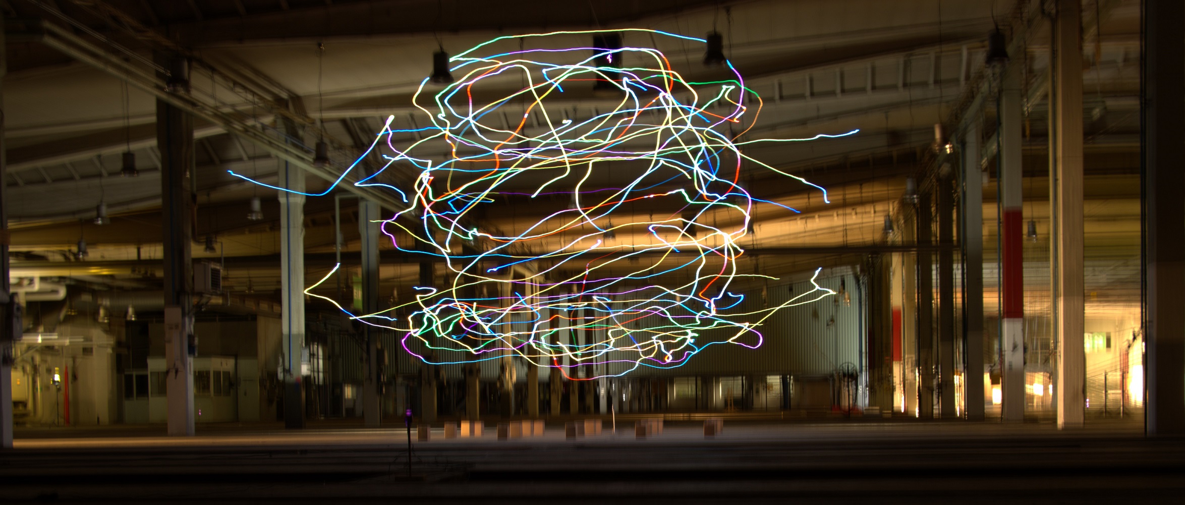
The video
But, enough talking, here is the never-seen-before New Year’s Eve video
And if you’re curious to see behind the scenes
Thanks to CollMot for their presence and valuable expertise, and InDiscourse for arranging the video!
And with the final blogpost of 2022 and this amazing video, it’s time to wish you a nice New Year’s Eve and a happy beginning of 2023!
Bolt DSHOT support for ESCs configurable via Kconfig
ESC pass-though configuration via USB (virtual COM port)
For more information (and files for the release) see the release notes and files on GitHub, the releases of the different projects are listed below. As always, we’re really eager to get feedback, so let us know if you try it out and how it works!
Our Ultra Wide Band (UWB) based positioning system, the Loco Positioning System, has been around for a long time and is still going strong! In this post we will tell you a bit about how it works (for those that don’t know about it yet), what research that is on-going in the field and new developments.
Crazyflie with Loco deck
Basics
UWB is using high frequency, low power, wide band radio where one of the most important properties is that it is possible to detect when a packet is received with very high accuracy. Combining this with very high frequency clocks, opens up the possibility to measure the time it takes for a radio packet to travel from a transmitter to a receiver. Since radio waves propagates with the speed of light in air we can convert the time into distance, and this is the basic idea in UWB positioning.
Not only is it possible to measure the timing of transmissions, the packets can also contain data, like in other radio standards. This property is extensively used to include time stamps of when a packet is sent, and also for instance the time stamp of when the transmitter received other packets or the position of an anchor.
This sounds pretty straight forward, but there are (of course) some complications. We will mention some of them but not go into the details.
Reflections – radio waves bounce around on walls and objects. Luckily, the nature of UWB actually uses this to its advantage and works better indoors than out side.
The clocks in the transmitter and receiver are not synchronized – the Time Of Flight can unfortunately not simply be measured by subtracting reception time from transmission time as the time stamps originate from two different clocks. The problem can be solved by sending some more packets back and forth though.
Packet collisions – two transmitters can not send at the same time, one or both packets will be lost. Transmissions must be scheduled or packet loss must be handled.
Obstacles – obstacles between the transmitter and receiver changes the transmission time.
Antennas – the propagation time through the antenna is substantial and changes depending on the angle to the transmitter/receiver.
Radio interference – other radio sources may interfere with the UWB radio signals and add noise or packet loss.
Modes
The Loco Positioning System can run in two fundamentally different modes: Two Way Ranging (TWR) and Time Difference of Arrival (TDoA).
Two Way Ranging (TWR)
In TWR the Crazyflie measures the distance to one anchor at a time, over and over again. Each measurement in initiated by the Crazyflie and requires 4 messages to be sent between the Crazyflie and the anchor, two request-response pairs. The position is estimated by pushing the measured distances into the kalman estimator.
This mode only supports one Crazyflie, but has the advantage of being very robust and also works pretty well some distance outside the system.
Time Difference of Arrival (TDoA)
In TDoA the setup is different, the anchors are transmitting packets while the Crazyflie is passively listening to the traffic. From the received information it is unfortunately not possible to measure the distance to the anchors, but what we can get is the difference in distance to two anchors. For example, we might know that we are 0.54 meters closer to anchor 3 than anchor 6, or similar. It is possible to calculate the position from this information and similarly to TWR the measurements are pushed to the kalman estimator for further processing.
This mode supports unlimited numbers of Crazyflies (swarms) but is less robust compared to TWR, especially outside the system. TDoA is similar to how GPS works.
Research
There are many researchers that use the Loco System, some use it as a positioning system and investigate topics like path planning or similar, while some others are looking at different questions related to the UWB positioning itself. We will not try to mention everyone, we probably only know of a small fraction of what is going on (please tell us!), but would like to point out two areas of research.
The first is related to improving the estimated position by handling measurement errors and the environment in a better way. Examples of this is to compensate for differences in reception angle or handling of obstacles in the space. We would like to mention Wenda Zhao’s work at the Dynamic Systems Lab, University of Toronto. He has contributed the robust TDoA implementation in the kalman estimator (blog post) as well as a public TDoA data set.
The second is inter drone ranging, that is measuring the distance between drones as an addition to, or instead of drone-to-anchor measurements. Examples in this are are the work by Dr Feng Shan at School of Computer Science and Engineering Southeast University, China (blog post) and professor Klaus Kefferpütz, Hochschule Augsburg, work on “Crazyflie quadcopter in decentralized swarming” as presented on the BAM days last year.
Experimental functionality
Even though there has not been a lot of code committed lately in our repositories related to the Loco Positioning System, it has been simmering in the background. We would like to mention what is cooking in the pots and some of the stuff that has been discussed or tested.
System size
An 8 anchor Loco Positioning System can cover a flight space of around 8×8 meters, but from time to time we get the question of larger systems. TDoA3 was designed with this in mind and supports up to 255 anchors, which in theory would make it possible to build larger systems. This functionality was implemented 4 years ago but we never really tested it(!). Finally we collected all anchors in the lab an set up 20 anchors in the same system, and it worked! This should make it possible to extend systems to at least 15×15 meters, but maybe even more with some clever radio cell planing.
Another possibility to enlarge a system is to tweak the radio settings to make them reach longer. There is a “Longer range” mode in TDoA3 that lowers the bit rate, but again it has not really been verified. This was also tested in the latest Loco frenzy and with some minor modifications it worked the way we hoped, with 20 anchors! The tests mainly verified that the anchors play nicely together, and we are not sure about the maximum range (to be tested) but we believe distances of up to 40 meters between anchors is possible. To use this feature you should make sure to use the latest firmware for the Loco Nodes as well as the Crazyflie.
The two features mentioned above should hopefully make it possible to go big and we hope it could be used for shows for instance.
TDoA3 hybrid mode
If one looks at the messages sent in a TDoA system, the anchors are actually doing TWR with each other, while the Crazyflie(s) are just listening to the traffic and that the possibility to extract the position is a nice “side effect”. Now imagine if the Crazyflies were to send some messages from time to time, then they could act as “dynamic” anchors, or do inter-drone ranging with each other. This is something we call TDoA3 hybrid mode.
Currently there is no official implementation of the Hybrid mode, only some experimental hacks. Some researchers have done their own implementations, but we hope, at some point, to generalize the functionality and integrate it into the firmware.
Read more
If you are interested to read more about positioning and the Loco system, you can take a look at the following link list.
Summer is coming and with that vacations, yeay! There will always be someone at the office to help you if you need help, and we will handle shipping through out the summer, but it might take a bit longer than usual.
This week we have a guest blog post from Dr Feng Shan at School of Computer Science and Engineering Southeast University, China. Enjoy!
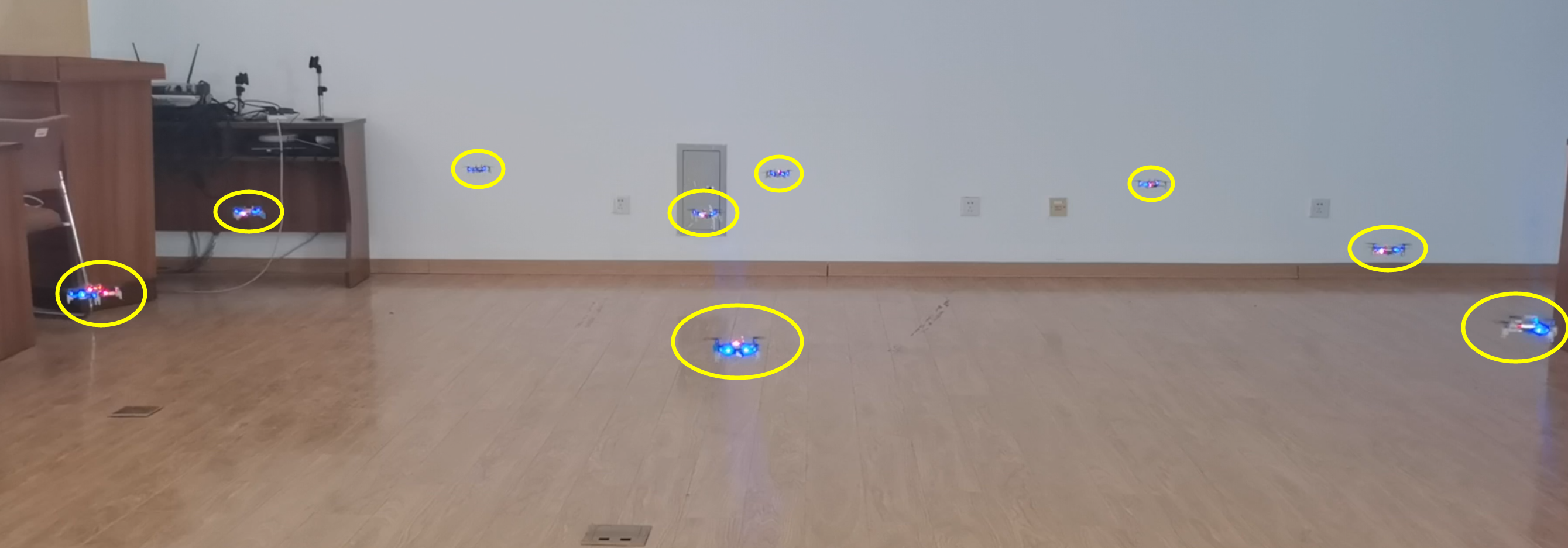
It is possible to utilize tens and thousands of Crazyflies to form a swarm to complete complicated cooperative tasks, such as searching and mapping. These Crazyflies are in short distance to each other and may move dynamically, so we study the dynamic and dense swarms. The ultra-wideband (UWB) technology is proposed to serve as the fundamental technique for both networking and localization, because UWB is so time sensitive that an accurate distance can be calculated using the transmission and receive timestamps of data packets. We have therefore designed a UWB Swarm Ranging Protocol with key features: simple yet efficient, adaptive and robust, scalable and supportive. It is implemented on Crazyflie 2.1 with onboard UWB wireless transceiver chips DW1000.
Fig.1. Nine Crazyflies are in a compact space ranging the distance with each other.
The Basic Idea
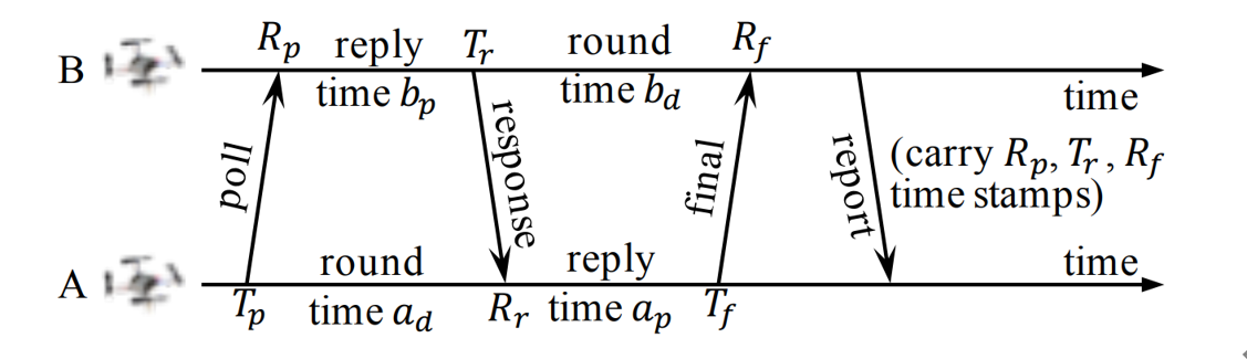
The basic idea of the swarm ranging protocol was inspired by Double Sided-Two Way Ranging (DS-TWR), as shown below.
Fig.2. The exsiting Double Sided-Two Way Ranging (DS-TWR) protocol.
There are four types of message in DS-TWR, i.e., poll, response, final and report message, exchanging between the two sides, A and B. We define their transmission and receive timestamps are Tp, Rp, Tr, Rr, Tf, and Rf, respectively. We define the reply and round time duration for the two sides as follows.
Let tp be the time of flight (ToF), namely radio signal propagation time. ToF can be calculated as Eq. (2).
Then, the distance can be estimated by the ToF.
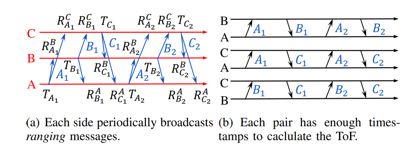
In our proposed Swarm Ranging Protocol, instead of four types of messages, we use only one type of message, which we call the ranging message.
Fig.3. The basic idea of the proposed Swarm Ranging Protocol.
Three sides A, B and C take turns to transmit six messages, namely A1, B1, C1, A2, B2, and C2. Each message can be received by the other two sides because of the broadcast nature of wireless communication. Then every message generates three timestamps, i.e., one transmission and two receive timestamps, as shown in Fig.3(a). We can see that each pair has two rounds of message exchange as shown in Fig.3(b). Hence, there are sufficient timestamps to calculate the ToF for each pair, that means all three pairs can be ranged with each side transmitting only two messages. This observation inspires us to design our ranging protocol.
Protocol Design
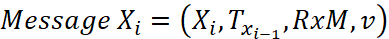
The formal definition of the i-th ranging message that broadcasted by Crazyflie X is as follows.
Xi is the message identification, e.g., sender and sequence number; Txi-1 is the transmission timestamp of Xi-1, i.e., the last sent message; RxM is the set of receive timestamps and their message identification, e.g., RxM = {(A2, RA2), (B2, RB2)}; v is the velocity of X when it generates message Xi.
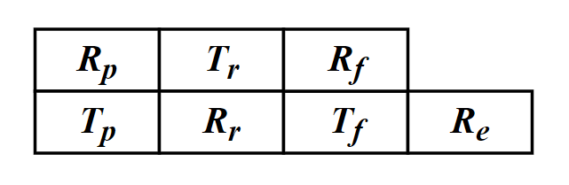
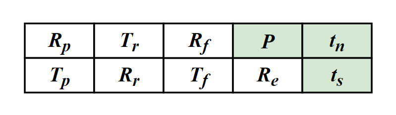
As mentioned above, six timestamps (Tp, Rp, Tr, Rr, Tf, Rf,) are needed to calculate the ToF. Therefore, for each neighbor, an additional data structure is designed to store these timestamps which we named it the ranging table, as shown in Fig.4. Each device maintains one ranging table for each known neighbor to store the timestamps required for ranging.
Fig.4. The ranging table, one for each neighbor.
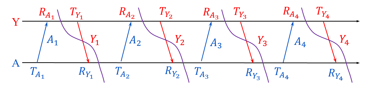
Let’s focus on a simple scenario where there are a number of Crazyflies, A, B, C, etc, in a short distance. Each one of them transmit a message that can be heard by all others, and they broadcast ranging messages at the same pace. As a result, between any two consecutive message transmission, a Crazyflie can hear messages from all others. The message exchange between A and Y is as follows.
Fig.5. Message exchange between A and Y.
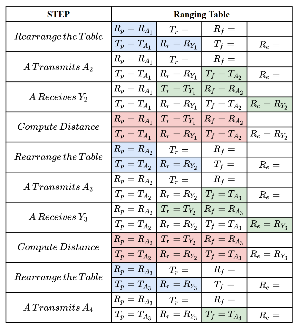
The following steps show how the ranging messages are generated and the ranging tables are updated to correctly compute the distance between A and Y.
Fig.6. How the ranging message and ranging table works to compute distance.
The message exchange between A and Y could be also A and B, A and C, etc, because they are equal, that’s means A could perform the ranging process above with all of it’s neighbors at the same time.
To handle dense and dynamic swarm, we improved the data structure of ranging table.
Fig.7. The improved ranging table for dense and dynamic swarm.
There are three new notations P, tn, ts, denoting the newest ranging period, the next (expected) delivery time and the expiration time, respectively.
For any Crazyflie, we allow it to have different ranging period for different neighbors, instead of setting a constant period for all neighbors. So, not all neighbors’ timestamps are required to be carried in every ranging message, e.g., the receive timestamp to a far apart and motionless neighbor is required less often. tn is used to measure the priority of neighbors. Also, when a neighbor is not heard for a certain duration, we set it as expired and will remove its ranging table.
If you are interested in our protocol, you can find much more details in our paper, that has just been published on IEEE International Conference on Computer Communications (INFOCOM) 2021. Please refer the links at the bottom of this article for our paper.
Implementation
We have implemented our swarm ranging protocol for Crazyflie and it is now open-source. Note that we have also implemented the Optimized Link State Routing (OLSR) protocol, and the ranging messages are one of the OLSR messages type. So the “Timestamp Message” in the source file is the ranging message introduced in this article.
The procedure that handles the ranging messages is triggered by the hardware interruption of DW1000. During such procedure, timestamps in ranging tables are updated accordingly. Once a neighbor’s ranging table is complete, the distance is calculated and then the ranging table is rearranged.
All our codes are stored in the folder crazyflie-firmware/src/deck/drivers/src/swarming.
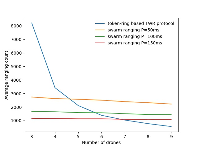
The following figure is a ranging performance comparison between our ranging protocol and token-ring based TWR protocol. It’s clear that our protocol handles the large number of drones smoothly.
Fig.8. performance comparison.
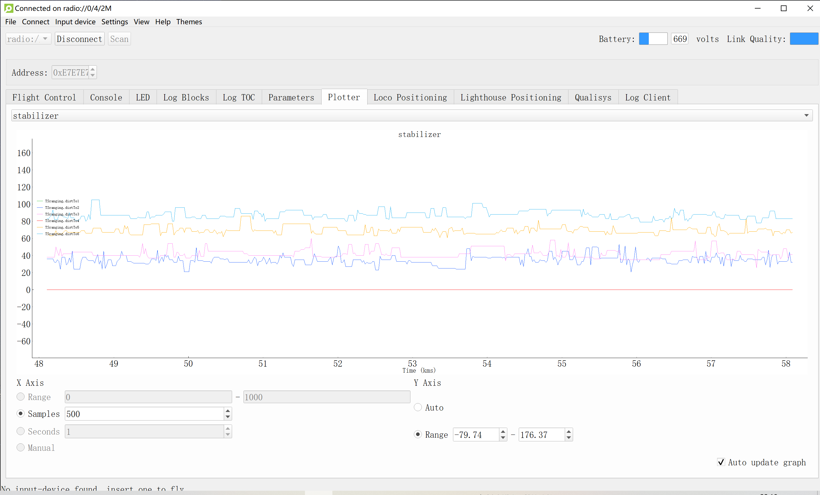
We also conduct a collision avoidance experiment to test the real time ranging accuracy. In this experiment, 8 Crazyflie drones hover at the height 70cm in a compact area less than 3m by 3m. While a ninth Crazyflie drone is manually controlled to fly into this area. Thanks to the swarm ranging protocol, a drone detects the coming drone by ranging distance, and lower its height to avoid collision once the distance is small than a threshold, 30cm.
cd crazyflie-firmware/src/deck/drivers/src/swarming
Then build the firmware.
make clean
make
Flash the cf2.bin.
cfloader flash path/to/cf2.bin stm32-fw
Open the client, connect to one of the drones and add log variables. (We use radio channel as the address of the drone) Our swarm ranging protocol allows the drones to ranging with multiple targets at the same time. The following shows that our swarm ranging protocol works very efficiently.
Summary
We designed a ranging protocol specially for dense and dynamic swarms. Only a single type of message is used in our protocol which is broadcasted periodically. Timestamps are carried by this message so that the distance can be calculated. Also, we implemented our proposed ranging protocol on Crazyflie drones. Experiment shows that our protocol works very efficiently.
This week we have a guest blog post from Wenda Zhao, Ph.D. candidate at the Dynamic System Lab (with Prof. Angela Schoellig), University of Toronto Institute for Aerospace Studies (UTIAS). Enjoy!
Accurate indoor localization is a crucial enabling capability for indoor robotics. Small and computationally-constrained indoor mobile robots have led researchers to pursue localization methods leveraging low-power and lightweight sensors. Ultra-wideband (UWB) technology, in particular, has been shown to provide sub-meter accurate, high-frequency, obstacle-penetrating ranging measurements that are robust to radio-frequency interference, using tiny integrated circuits. UWB chips have already been included in the latest generations of smartphones (iPhone 12, Samsung Galaxy S21, etc.) with the expectation that they will support faster data transfer and accurate indoor positioning, even in cluttered environments.
A Crazyflie with an IMU and UWB tag flies through a cardboard tunnel. A vision-based motion capture system would not be able to achieve this due to the occlusion.
In our lab, we show that a Crazyflie nano-quadcopter can stably fly through a cardboard tunnel with only an IMU and UWB tag, from Bitcraze’s Loco Positioning System (LPS), for state estimation. However, it is challenging to achieve a reliable localization performance as we show above. Many factors can reduce the accuracy and reliability of UWB localization, for either two-way ranging (TWR) or time-difference-of-arrival (TDOA) measurements. Non-line-of-sight (NLOS) and multi-path radio propagation can lead to erroneous, spurious measurements (so-called outliers). Even line-of-sight (LOS) UWB measurements exhibit error patterns (i.e., bias), which are typically caused by the UWB antenna’s radiation characteristics. In our recent work, we present an M-estimation-based robust Kalman filter to reduce the influence of outliers and achieve robust UWB localization. We contributed an implementation of the robust Kalman filter for both TWR and TDOA (PR #707 and #745) to Bitcraze’s crazyflie-firmware open-source project.
Methodology
The conventional Kalman filter, a primary sensor fusion mechanism, is sensitive to measurement outliers due to its minimum mean-square-error (MMSE) criterion. To achieve robust estimation, it is critical to properly handle measurement outliers. We implement a robust M-estimation method to address this problem. Instead of using a least-squares, maximum-likelihood cost function, we use a robust cost function to downweigh the influence of outlier measurements [1]. Compared to Random Sample Consensus (RANSAC) approaches, our method can handle sparse UWB measurements, which are often a challenge for RANSAC.
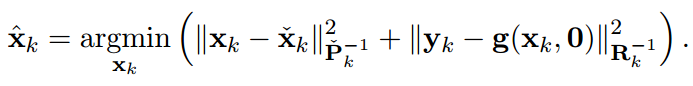
From the Bayesian maximum-a-posteriori perspective, the Kalman filter state estimation framework can be derived by solving the following minimization problem:
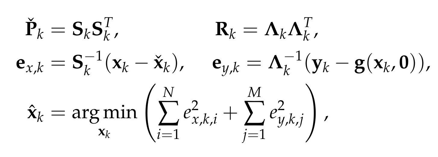
Therein, xk and yk are the system state and measurements at timestep k. Pk and Rk denote the prior covariance and measurement covariance, respectively. The prior and posteriori estimates are denoted as xk check and xk hat and the measurement function without noise is indicated as g(xk,0). Through Cholesky factorization of Pk and Rk, the original optimization problem is equivalent to
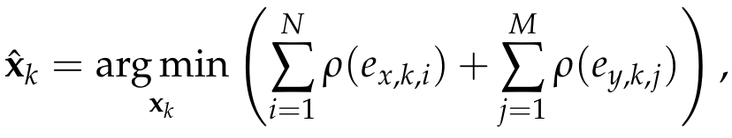
where ex,k,i and ey,k,j are the elements of ex,k and ey,k. To reduce the influence of outliers, we incorporate a robust cost function into the Kalman filter framework as follows:
where rho() could be any robust function (G-M, SC-DCS, Huber, Cauchy, etc.[2]).
By introducing a weight function for the process and measurement uncertainties—with e as input—we can translate the optimization problem into an Iteratively Reweighted Least Squares (IRLS) problem. Then, the optimal posteriori estimate can be computed through iteratively solving the least-squares problem using the robust weights computed from the previous solution. In our implementation, we use the G-M robust cost function and the maximum iteration is set to be two for computational reasons. For further details about the robust Kalman filter, readers are referred to our ICRA/RA-L paper and the onboard firmware (mm_tdoa_robust.c and mm_distance_robust.c).
Performance
We demonstrate the effectiveness of the robust Kalman filter on-board a Crazyflie 2.1. The Crazyflie is equipped with an IMU and an LPS UWB tag (in TDOA2 mode). With the conventional onboard extended Kalman filter, the drone is affected by measurement outliers and jumps around significantly while trying to hover. In contrast, with the robust Kalman filter, the drone shows a more reliable localization performance.
Conventional extended Kalman filter
M-estimation-based robust Kalman filter
Quadcopter is commanded to hover. UWB TDOA-based localization performance of standard method on-board a Crazyflie 2.1 quadcopter (left) and the proposed robust Kalman filter (right).
The robust Kalman filter implementations for UWB TWR and TDOA localization have been included in the crazyflie-firmware master branch as of March 2021 (2021.03 release). This functionality can be turned on by setting a parameter (robustTwr or robustTdoa) in estimator_kalman.c. We encourage LPS users to check out this new functionality.
As we mentioned above, off-the-shelf, low-cost UWB modules also exhibit distinctive and reproducible bias patterns. In our recent work, we devised experiments using the LPS UWB modules and showed that the systematic biases have a strong relationship with the pose of the tag and the anchors as they result from the UWB radio doughnut-shaped antenna pattern. A pre-trained neural network is used to approximate the systematic biases. By combining bias compensation with the robust Kalman filter, we obtain a lightweight, learning-enhanced localization framework that achieves accurate and reliable UWB indoor positioning. We show that our approach runs in real-time and in closed-loop on-board a Crazyflie nano-quadcopter yielding enhanced localization performance for autonomous trajectory tracking. The dataset for the systematic biases in UWB TDOA measurements is available on our Open-source Code & Dataset webpage. We are also currently working on a more comprehensive dataset with IMU, UWB, and optical flow measurements and again based on the Crazyflie platform. So stay tuned!
Reference
[1] L. Chang, K. Li, and B. Hu, “Huber’s M-estimation-based process uncertainty robust filter for integrated INS/GPS,” IEEE Sensors Journal, 2015, vol. 15, no. 6, pp. 3367–3374.
[2] K. MacTavish and T. D. Barfoot, “At all costs: A comparison of robust cost functions for camera correspondence outliers,” in IEEE Conference on Computer and Robot Vision (CRV). 2015, pp. 62–69.
Feel free to contact us if you have any questions or suggestions: wenda.zhao@robotics.utias.utoronto.ca.
Please cite this as:
<code>@ARTICLE{Zhao2021Learningbased,
author={W. {Zhao} and J. {Panerati} and A. P. {Schoellig}},
title={Learning-based Bias Correction for Time Difference of Arrival Ultra-wideband Localization of Resource-constrained Mobile Robots},
journal={IEEE Robotics and Automation Letters},
volume={6},
number={2},
pages={3639-3646},
year={2021},
publisher={IEEE}
doi={10.1109/LRA.2021.3064199}}
</code>