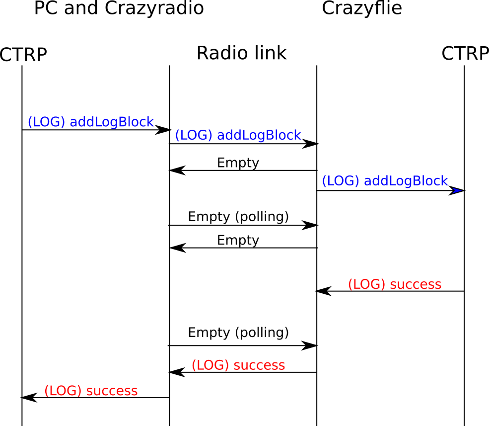
The communication protocols between a PC, a Crazyradio and a Crazyflie are critical parts of the Crazyflie ecosystem, they allow to communicate with and control the Crazyflies in real time. These protocols have been documented in a couple of blog posts already. They exist since the origin of the Crazyflie, in 2011, and where originally designed with one use-case in mind: controlling one Crazyflie manually from a game-pad connected to a PC. The Crazyflie can of course do much more nowadays, like flying in big autonomous swarm, but the underlying communication protocols are still an evolution of these simple manual-flights single Crazyflie origin.
Over time we have felt the limitations of the communications protocols and of the Crazyradio (PA). For this reason, lately, we have been starting to work at making a new, more modern, Crazyradio dongle and at revamping the communication protocol used to communicate with the Crazyflie. The aim is to start with the current Crazyflie use-cases including flying in centralized and decentralized swarms with varying levels of autonomy of the drone itself.
The first project is to make a new Crazyradio dongle: the current Crazyradio PA is based on an old nRF24 chip from Nordic semi. It runs on a 8051 microcontroller and has a mostly hardware-driven radio. This means that the processing power is quite limited and the radio has no flexibility with the on-air protocol and packet size limited to 32 Bytes. We are working on a new Crazyradio dongle based on an nRF52840 microcontroller and a RF power amplifier. We expect the new radio to be available sometimes before the summer 2023:
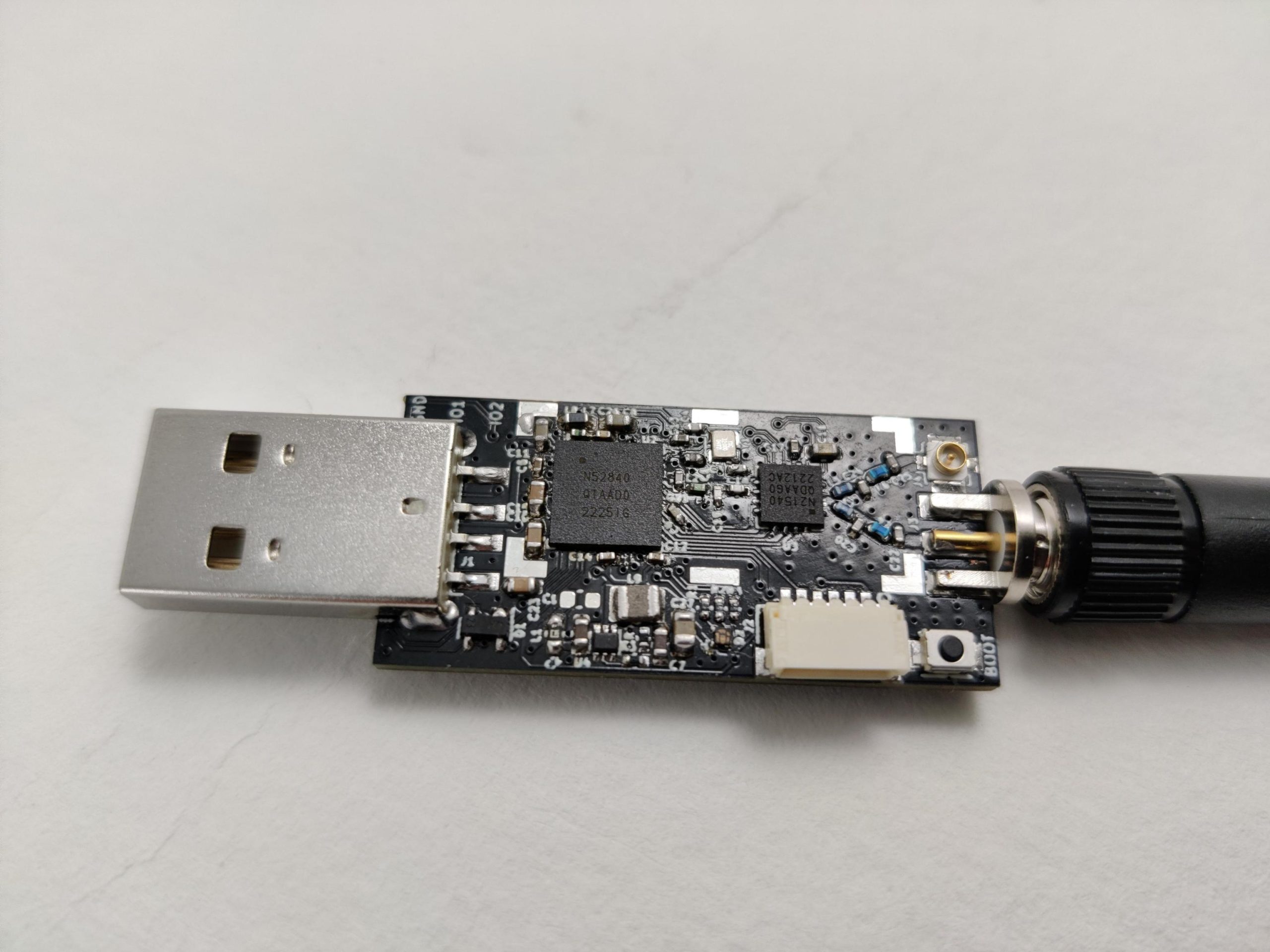
The main advantage of using the new nRF52 microcontroller is that it is an ARM Cortex-M4 chip with quite a lot of flash and ram. This will make development much easier and faster. It is also a much more capable chip which will improve communication performance. The output power will be similar to the Crazyradio PA so the range should be similar. The radio being more flexible, it will allow development of new protocols including the capability to send packets bigger than 32 bytes.
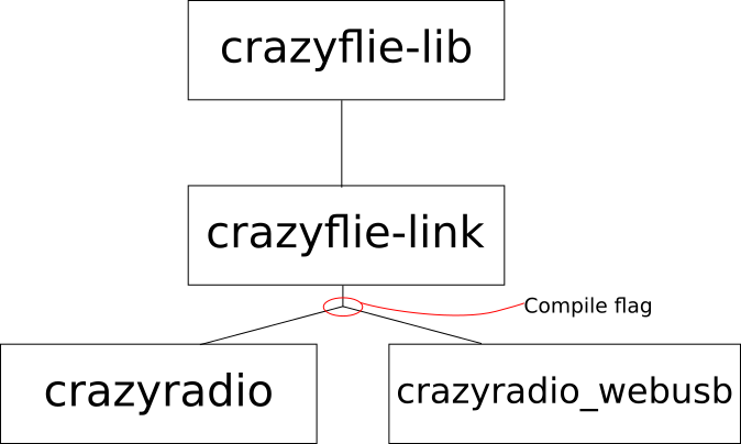
On the USB protocol side, we will take this opportunity to improve the USB protocol. We are making it more flexible so that it can be expanded more easily in the future and it will also be much more efficient when controlling swarm of Crazyflies.
The first version of the new Crazyradio will implement the same air-protocol as the current one, so there will not be a need to change the Crazyflie firmware right away.
However we are already thinking of a couple of new radio protocol that we want to develop for the new Crazyradio and the Crazyflie 2:
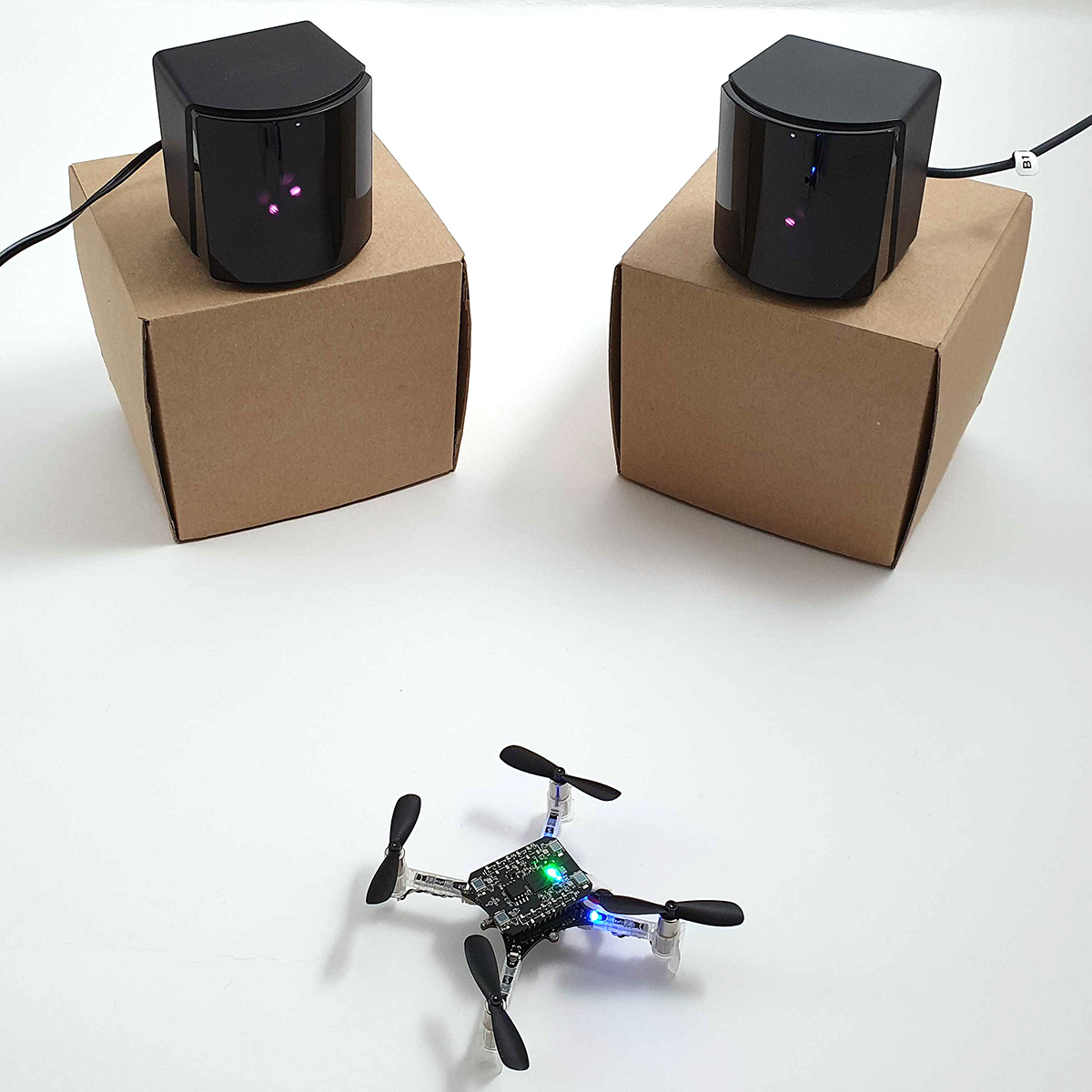
- A low latency channel hopping protocol: This protocol would allow to connect one or a swarm of Crazyflie using channel hopping. This means that the user does not have to setup a channel for communication anymore, the protocol will automatically hop form channel to channel randomly. This will make it much easier to connect to Crazyflies and make the link more reliable
- A P2P protocol that will allow Crazyflies and Crazyradios to talk to each other: the main idea is to make the P2P protocol a proper supported protocol and to make the Crazyradio able to be a node in the P2P network. This should simplify a lot the development of autonomous swarm.
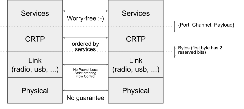
On the higher level protocol, CRTP, we are stating to think of ways to make new protocols as well. On that side, there has been no work started yet but a lot of ideas and general direction based on our experience and on feedback in iROS 2022 and other conferences. The basic lose ideas currently are:
- Integrating the concept of connection in the protocol: currently there is no such concept so for example if a logging is setup and the link is lost, the logging subsystem will continue to try to send packets forever. A more logical implementation would tell the logging subsystem that the connection is lost and so that the logging can be canceled.
- Basing the protocol on Remote Procedure Call: A lot of that we currently do in CRTP is to emulate procedure call with packets and parameters. Making procedure call the base unit of the protocol would make it much easier to use and extend
- Versioning! One of the problem currently is that without clear versioning, it is very hard to make the protocol evolve in a documented way. We will find a way to version so that we can improve, add and remove functionality when needed.
- Finally. We are not planning on running (micro) ROS in the Crazyflie 2, however the goal is to make a protocol that would make the interface to (micro) ROS and Crazyswarm as thin and boring as possible. Today the Crazyswarm ROS Crazyflie server is a full fledged client, the hope is to make the Crazyflie protocol in such a way that it would look more like a proxy to the Crazyflie RPC API.
If you have made a client that communicates directly with the Crazyradio PA, the change in the new Crazyradio will affect you. We will soon make the new Crazyradio 2 repos public with documentation of the new protocol to give the possibility to have discussions before release.
Those are still very lose ideas and the main goal of this blog post is to bring awareness to the future work: if you have any ideas, opinion or wishes when it comes to the communication protocol please come in contact with us and let’s discuss. The best forum is our github discussion page. Also we are planning to have an online townhall meeting so that we can handle any questions about implementation or discuss the proposed protocol, so keep an eye on this discussion thread: Townhall meeting (7 Dec 2022) · Discussion #426 · bitcraze (github.com).