For quite some time now we have had mobile apps that can be used to control the Crazyflie 2.x quadcopter. There is one iOS and one Android app available. There used to be a prototype of a Windows phone app but it has not survived the demise of Windows on phone (fun fact, the windows phone app can be compiled to run on XBox, however there is no USB access in there so it is quite useless). In this blog post I want to talk about the state of the apps and a possible future for them. As usual with me, the future should include a bit ot Rust :-).
Android app
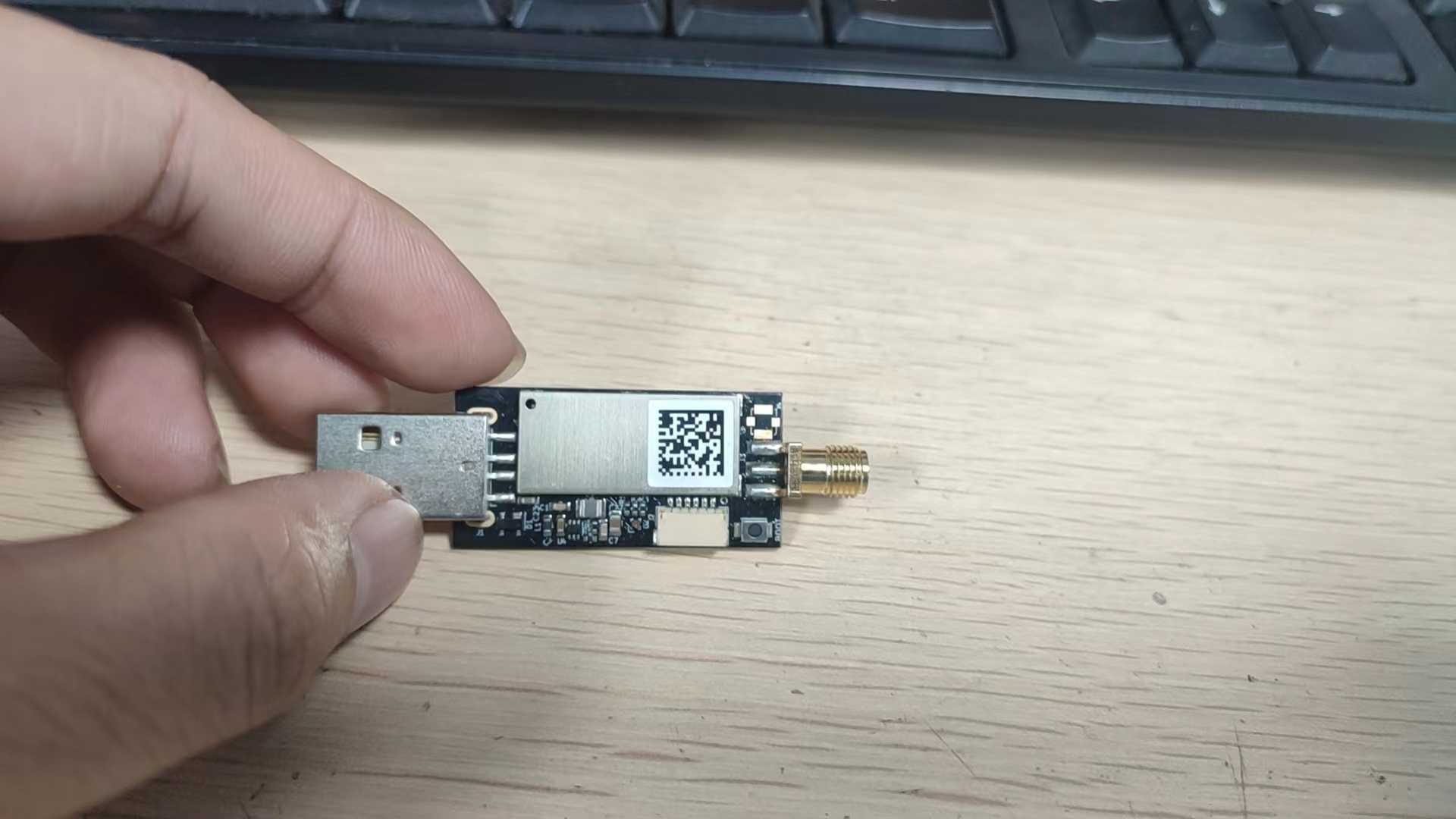
The Android app is the oldest of the mobile apps, it has been created originally to be used with a Crazyradio conncted to an Android phone over USB. Then, when we released Crazyflie 2.0 with Bluetooth Low Energy, BLE was added to the app to be able to Connect to a Crazyflie without radio attached.
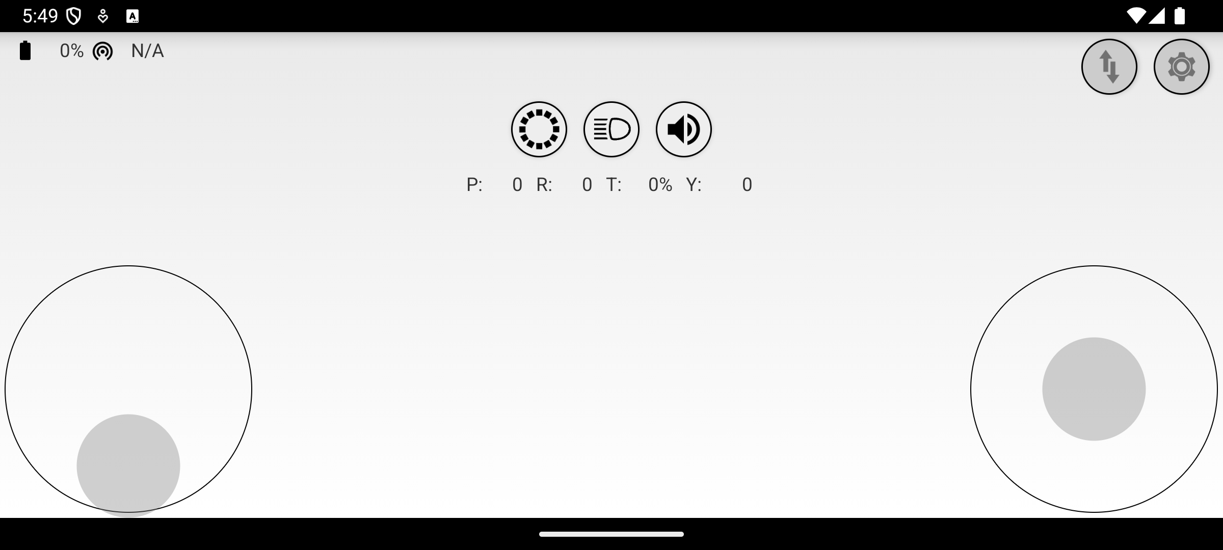
Over the years, the Android app has mainly been maintained by FredG, one of the very first Crazyflie contributors. The app supports controlling Crazyflie using touch-control as well as using an Android-supported Gamepad. It also has support for showing the Crazyflie console, controlling some decks and assisted flight using the flow deck.
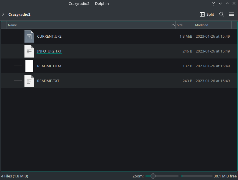
It also supports updating the Crazyflie firmware using a Crazyradio connected on USB. This functionality is unfortunately broken since we altered the update process when changing the Crazyflie bluetooth stack last year.
The Android app is also working on Chromebook. This means that it can be used to fly the Crazyflie form a chromebook using Crazyradio of BLE. This is one of the only way to control the Crazyflie from Bluetooth on a laptop.
iOS app
The iOS app is newer and much simpler. It has had a couple of really good contribution over the years but overall it has seen much less development than the Android app. I have tried to keep it up and working but nothing more so far.
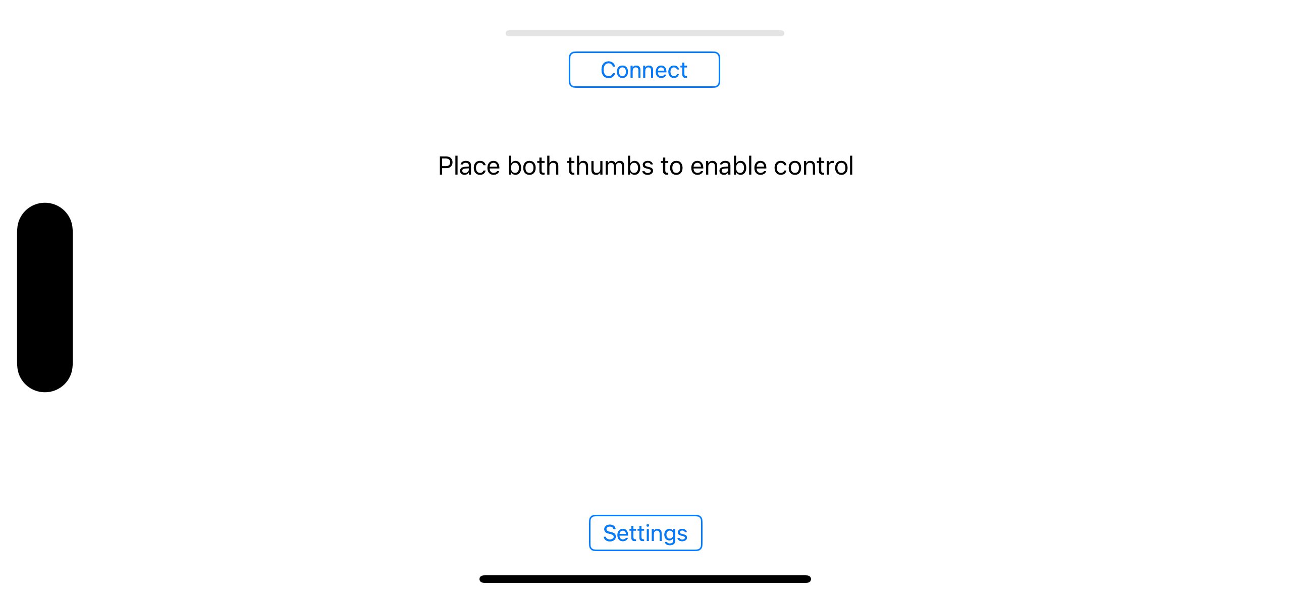
The iOS app was released when we made the Crazyflie 2.0. Since iOS does not let us communicate with USB devices, it can only work using Bluetooth Low Energy. It can control the Crazyflie using touch control as well as motion control using the IPhone gyroscope.
The iOS app also had support for updating the Crazyflie over Bluetooth, however, like for the Android app this is now broken and it has been removed in a recent release. I hope to be able to add it back soon.
With the advent of the Apple Silicon Mac, the iOS app is now also a Mac app. Like for the Android app on Chromebook, this gives the unique ability to communicate with the Crazyflie over Bluetooth from a computer. However it still has no USB support for Crazyradio and until we implement Gamepad support there is no way to control the Crazyflie from a Mac using the app.
The future
Some of the biggest issues for the development of the mobile app so far has been a lack of specification and the difficulty of re-implementing Crazyflie protocol for each app.
For the former, the apps have been created at a time where flying the Crazyflie manually was one of the major use-case. Nowadays, it is much more common to fly autonomously. This means that the apps should be able to do more to be really useful. Manual flight might still be needed to test the Crazyflie or just to play around. But the app could also have a much greater use for things like assisting in setting up positioning system or swarms. We are still not sure what would be needed or useful yet so if you have any ideas please tell us here as a comment or on Github discussions.
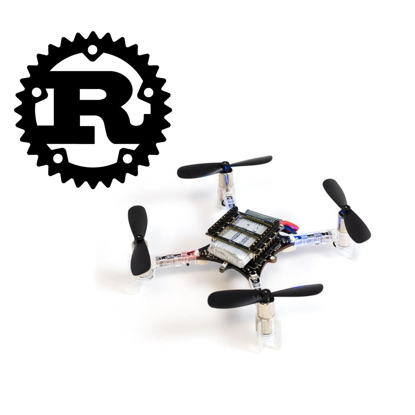
For the later, the difficulty of re-implementing the Crazyflie lib, this is something we have had problem with on multiple front. For example this is also a problem for ROS support and for Crazyswarm. The main problem is that the official Crazyflie lib is implemented in Python, and Python happens to not be a good choice for most cases due to limited portability and performance. One solution we have been imagining and working towards is to implement the Cazyflie lib in Rust and then implement binding for Python, C/C++, Java and Swift. This will cover our current python client, ROS, Crazyswarm as well as all the mobile app. It should allow to get much more done much more easily on mobile, since we will not have to start by re-implementing the wheel each time and will be able to focus on actual functionalities.
One idea, would be to start now with implementing the Crazyflie update algorithm in Rust and to use is from python and the mobile apps. This is a good first target, since this is a non-trivial really annoying piece of code in all languages, and it is also one that must be as bug-free as possible. So having a single implementation that is well tested and can be used everywhere would be very beneficial to the Crazyflie ecosystem.
I hope I managed to convey where we are and where we want to go with the mobile app. If you have any feedback please tell us about it.