Author: Hanna Müller

This early summer my research group (Center for Project-Based Learning at ETH Zürich) was in charge of a special week – high school students from all over Switzerland (actually even the world, they had to speak German though) could apply for a study week at different departments from our university. The departments which joined this initiative were mathematics, physics, biology, environmental sciences, material sciences, and our department, electrical engineering and information technologies (ITET). But how do you show teenagers between 15-19 in one week as much as possible from electrical engineering while also having fun? And best inspire them to study at ITET? Our solution was: drones. More specifically, Crazyflies. With those we had many possibilities to learn about electrical engineering – from sensors, microcontrollers, timers, and motors to LEDs, batteries, embedded systems, FreeRTOS tasks, state estimation, and controller – and all this with a high fun potential and a low risk of accidents, as with their weight of only 30g they hardly ever do any damage. In this blog post, I will guide you through our week, in hopes to help others who also want to use the Crazyflie to teach students about electrical engineering in a fun way.

Monday

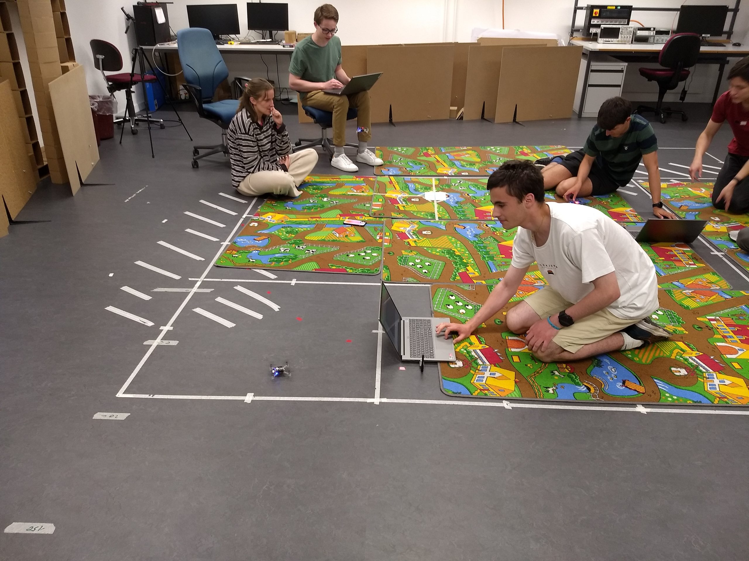
We started in the afternoon (in the morning they had a welcoming tour) with a short introduction and splitting the 20 students into groups of two (everyone got a paper slip and had to find the matching one, accelerometer gyroscope, pitch roll, UART SPI, and so on – this gives the lecturer a great opportunity for interaction with the students later on, once their word gets relevant during the week). After a short introduction to programming and microcontrollers we moved on to the most classic beginner task: blink an LED! We chose to use the front left one, as this one is only used when communicating – so as long as we don’t connect to the drone we can observe exactly what we programmed. Most students got the LED turned on rather quickly – however, pulsing the LED to change the intensity took them some more time and forced them to learn how to write loops. They also already learned how PWM works without knowing it yet – setting the intensity of an LED or the strength of a motor is about the same thing in the end after all and this gave us a great start for Tuesday.

Tuesday

On Tuesday we looked at hardware from different perspectives. As you might have guessed, we looked at motors and how to control them with PWM and timers. The students were a bit disappointed that we still didn’t fly, but as soon as they realized that they could play their favorite song on the motors the motivation was high again! We didn’t even have any stray drones, even though we let them mount the propellers (the songs sound much better with propellers).
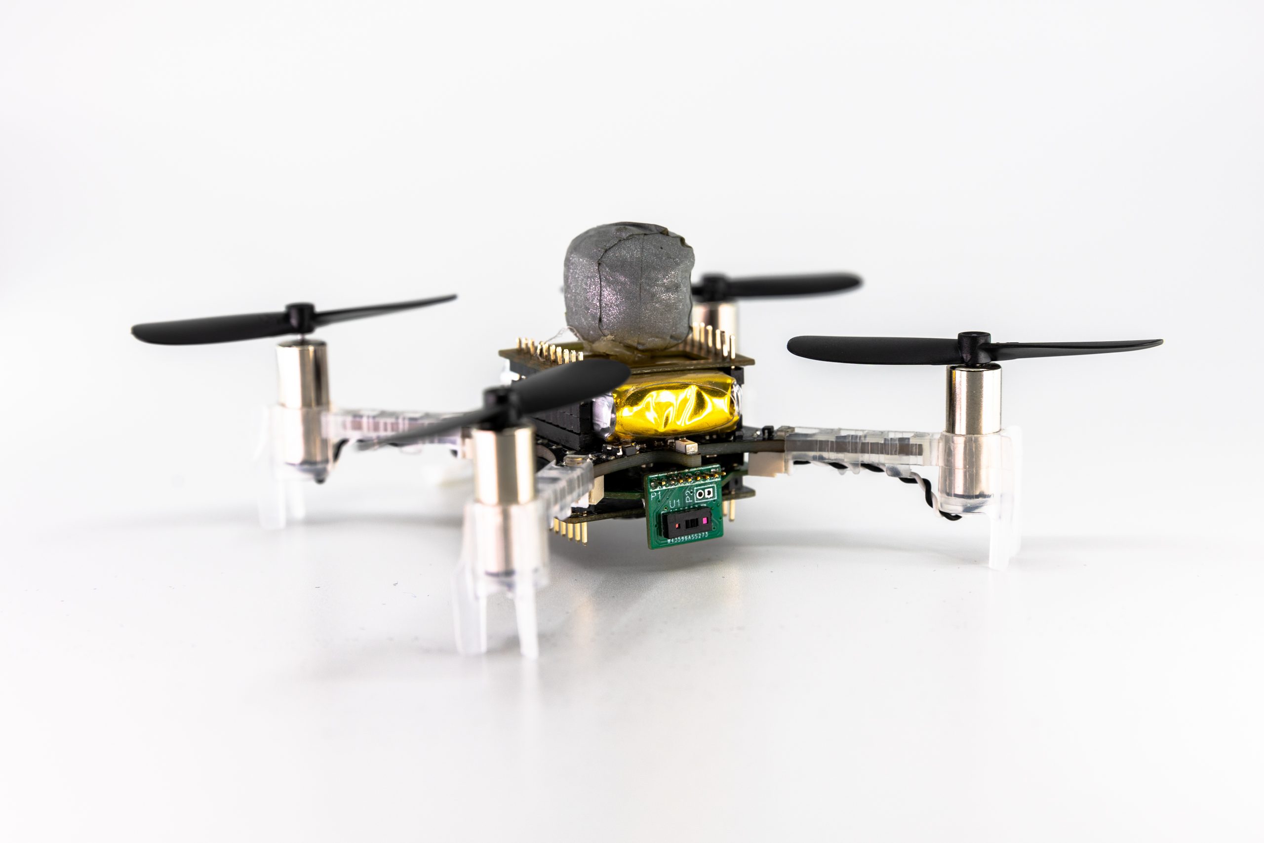
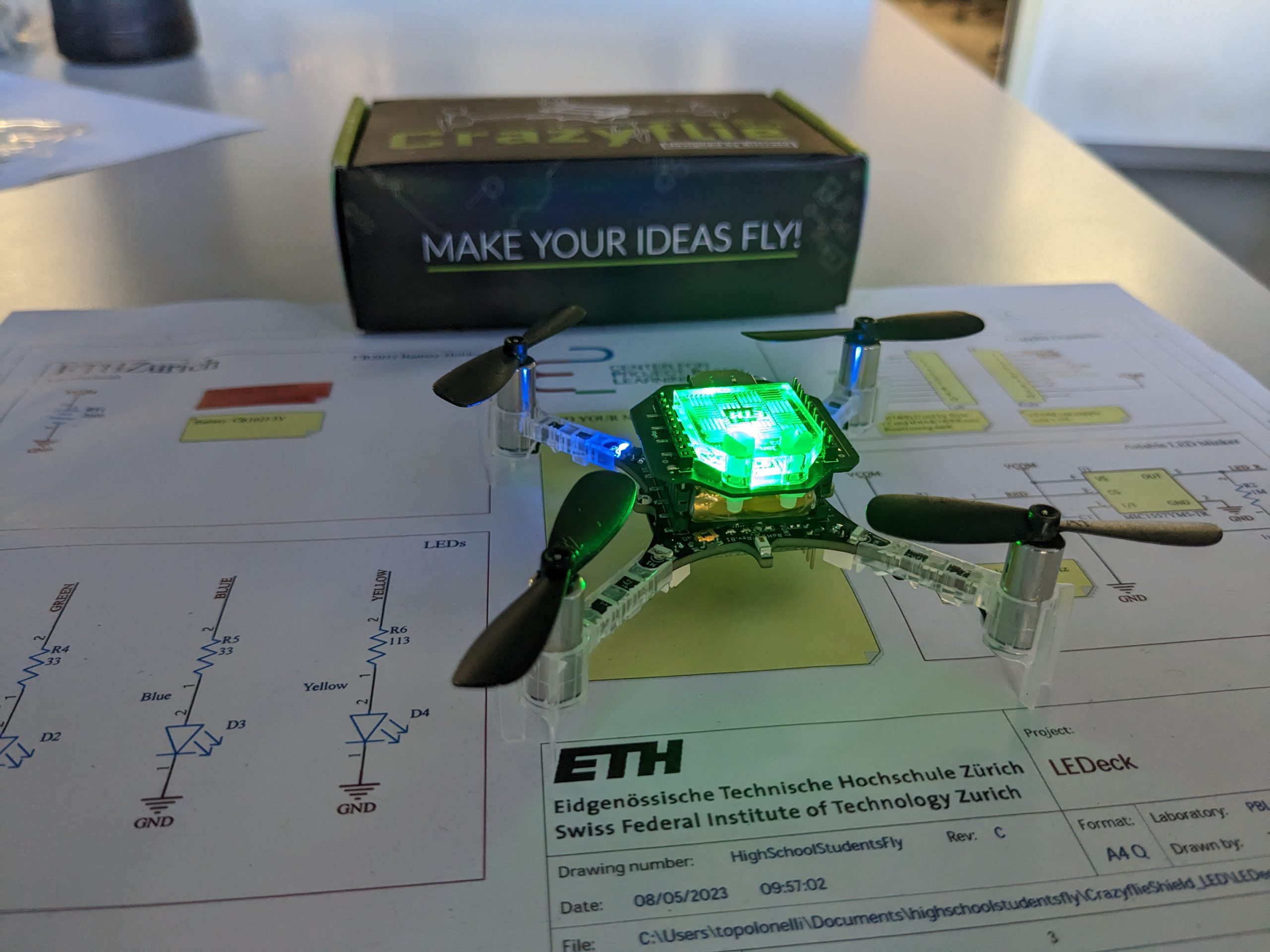
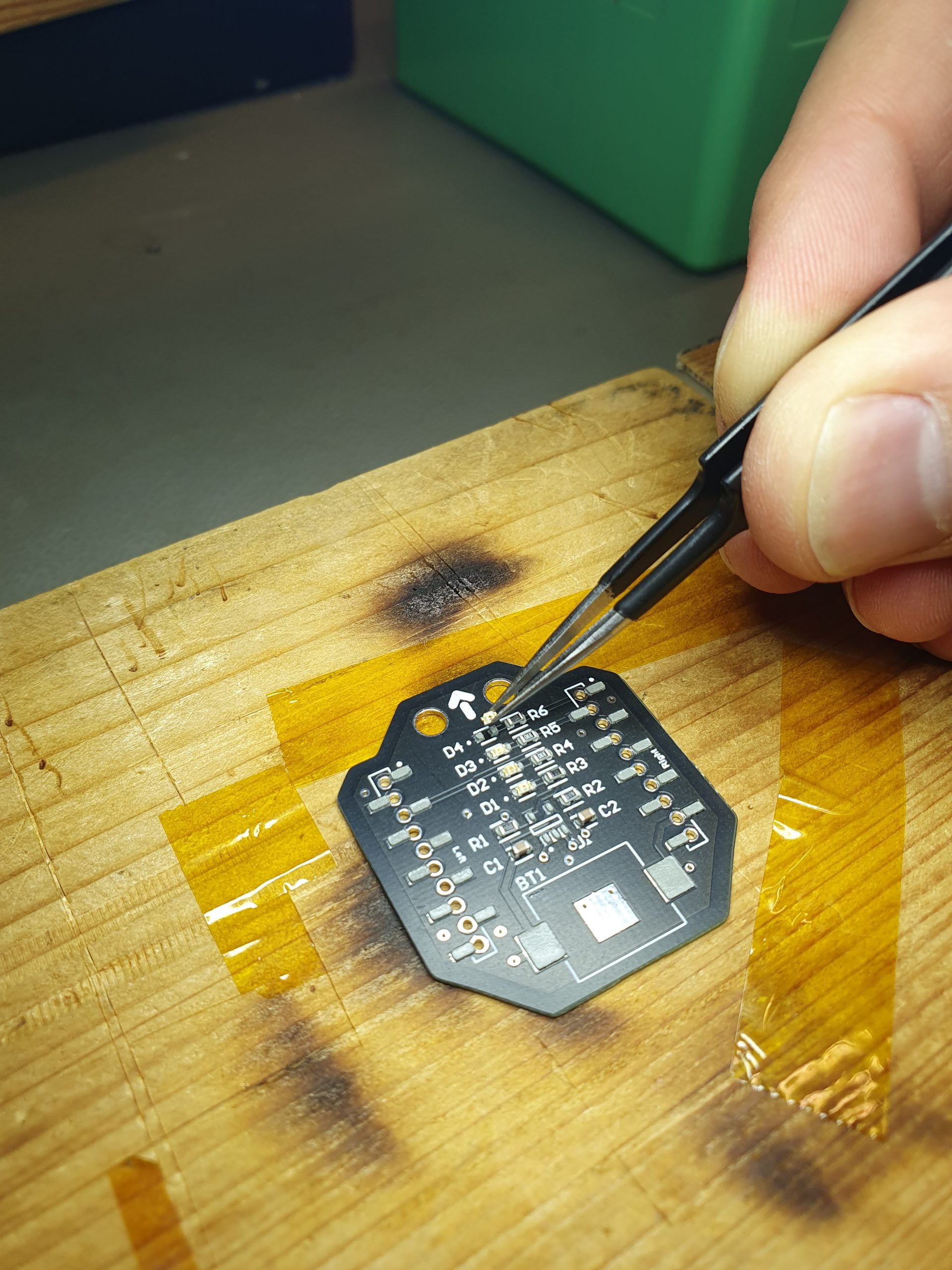
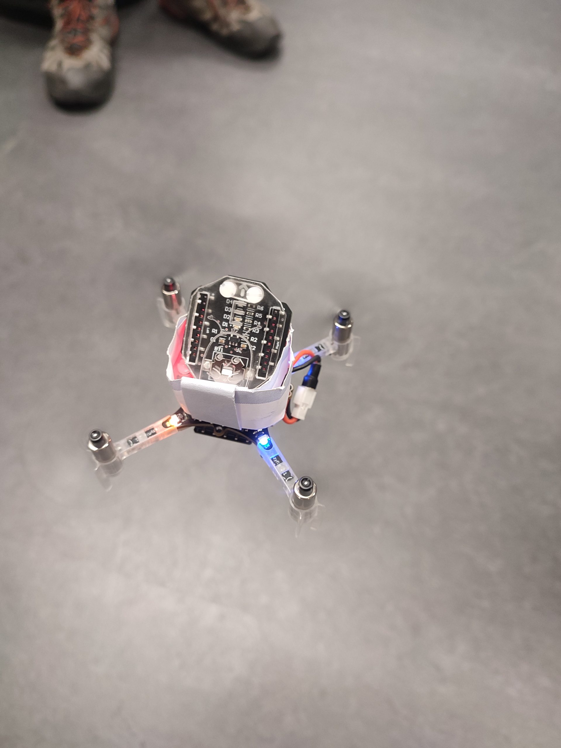
We also looked at another aspect of electrical engineering: PCB design (this was already done though) and soldering. For this, we prepared a custom deck, with four colored LEDs, which could be populated like in industry with solder paste and then soldered with a hot plate. To make it even more fun (and partly to show off our laser cutter) they also designed a small plastic diffuser that could be mounted on top. So in the end our setup resembles the LED ring – however, it can be mounted on top which is essential if you don’t want to fly with a positioning system (and therefore need to mount a flow deck).

Wednesday

Trying out the state estimation

Now that we knew how to blink LEDs and, even more important, how to control motors we had to learn a bit about how the drone actually figures out which motor should be turned on and how much. For this, we first looked at sensors and wired communication protocols, such as I2C (for the IMU and time-of-flight sensor), SPI (for the optical flow), and UART (to the nRF) – due to limited time we didn’t go into details here though. We briefly touched wireless communication, to explain how the commands they will later send to the drone (and the firmware) are actually sent to the right drone.

Tuning PIDs

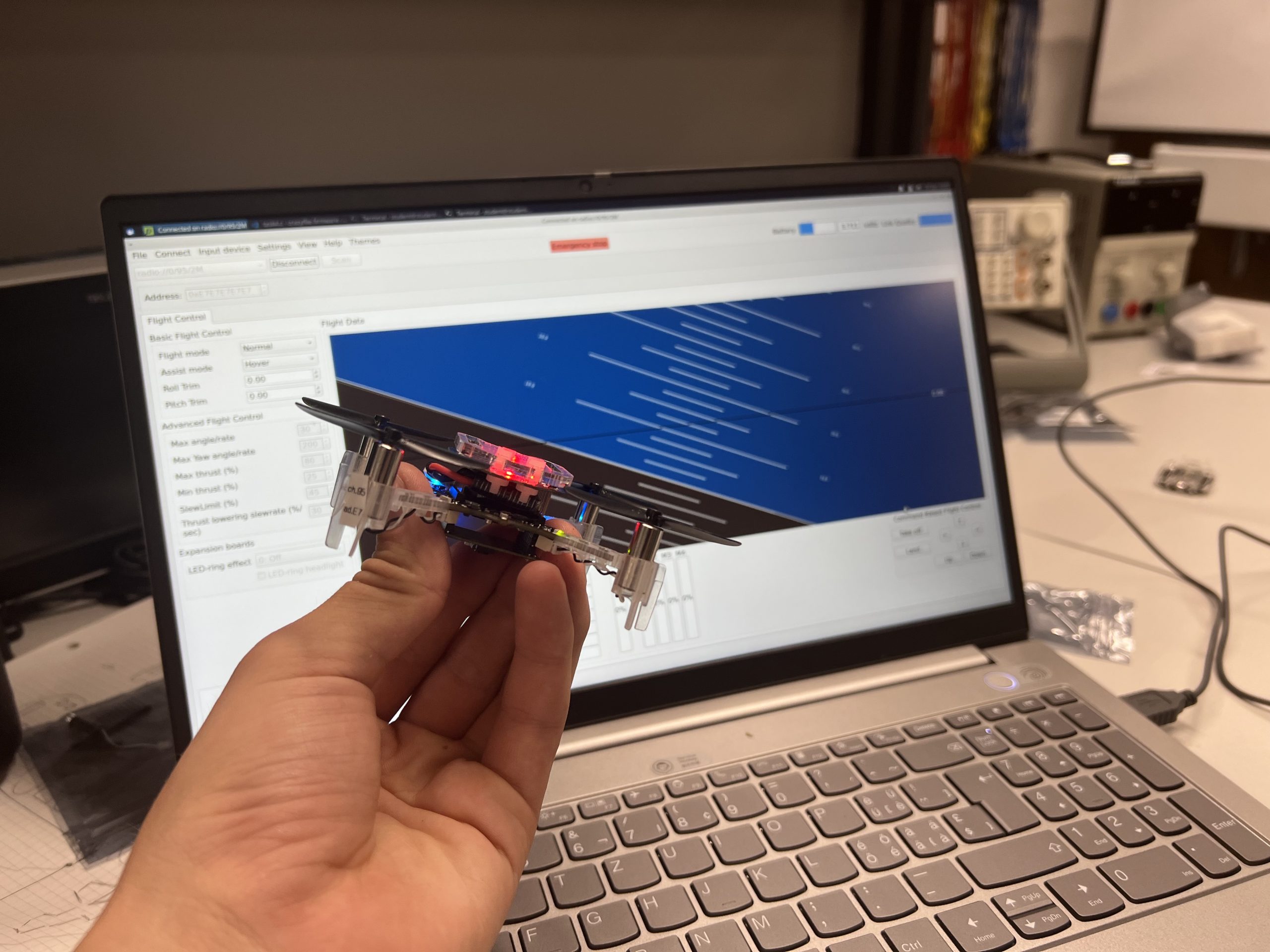
We moved on to what state estimation is in general – again jumping over all details of an extended Kalman Filter, but had a closer look at the logging and parameter system. We then spent a bit more time on the PID controller again – which was also a bit hard to explain, as half the teenagers hadn’t learned how to integrate and differentiate yet. However, they learned fast and we could move to the part they waited for all week long: Flying (and tuning the PID).

Thursday

Transport drone

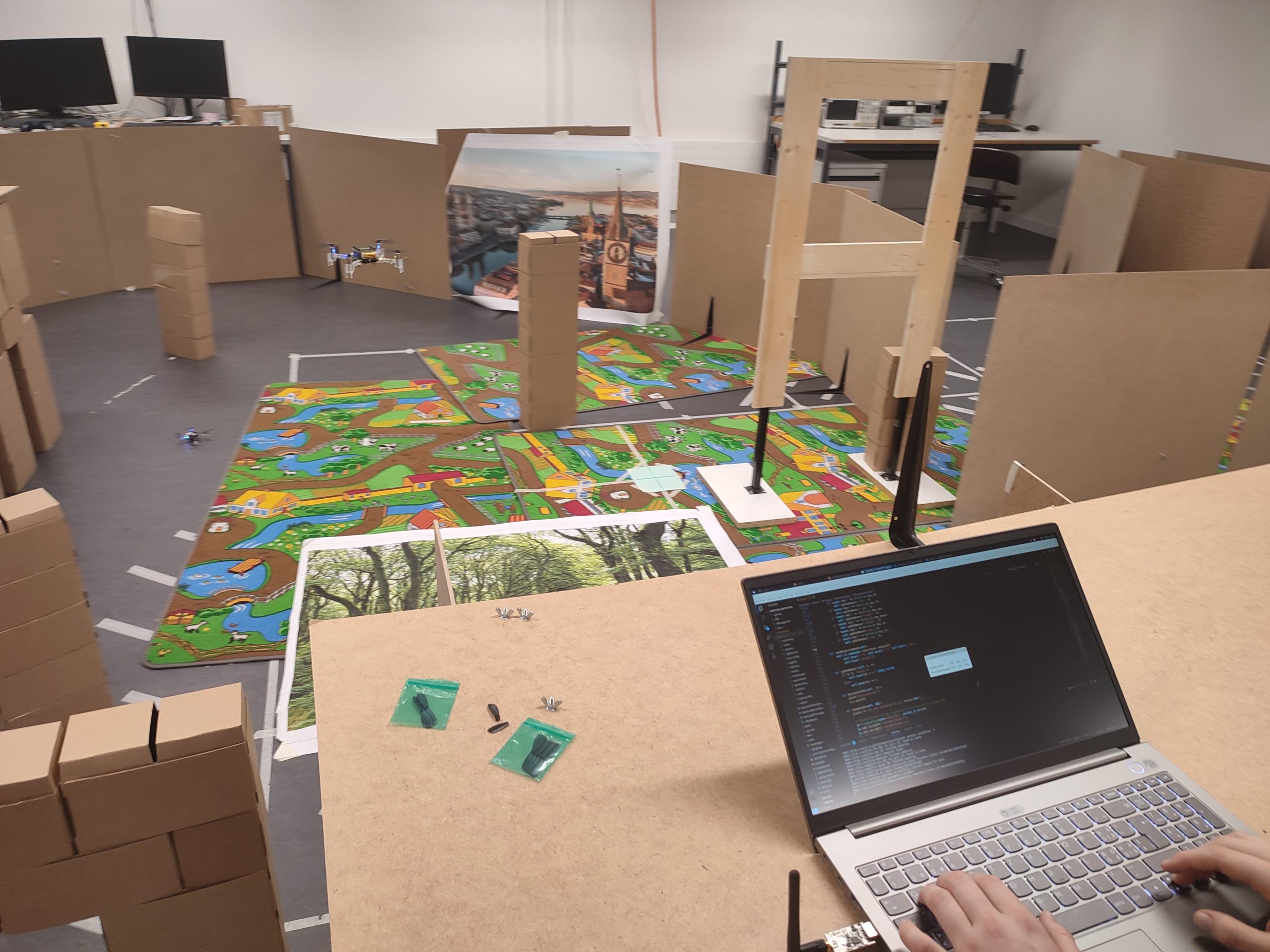
This was the day that was meant for creativity – the students could choose themselves which project they want to achieve. We proposed them some ideas, such as blinking LEDs depending on the height, flying through a gate (the challenge here is to filter the height measurements when the gate border is below the drone), steering the drone with the keyboard, soldering an own sensor on a break-out board, …

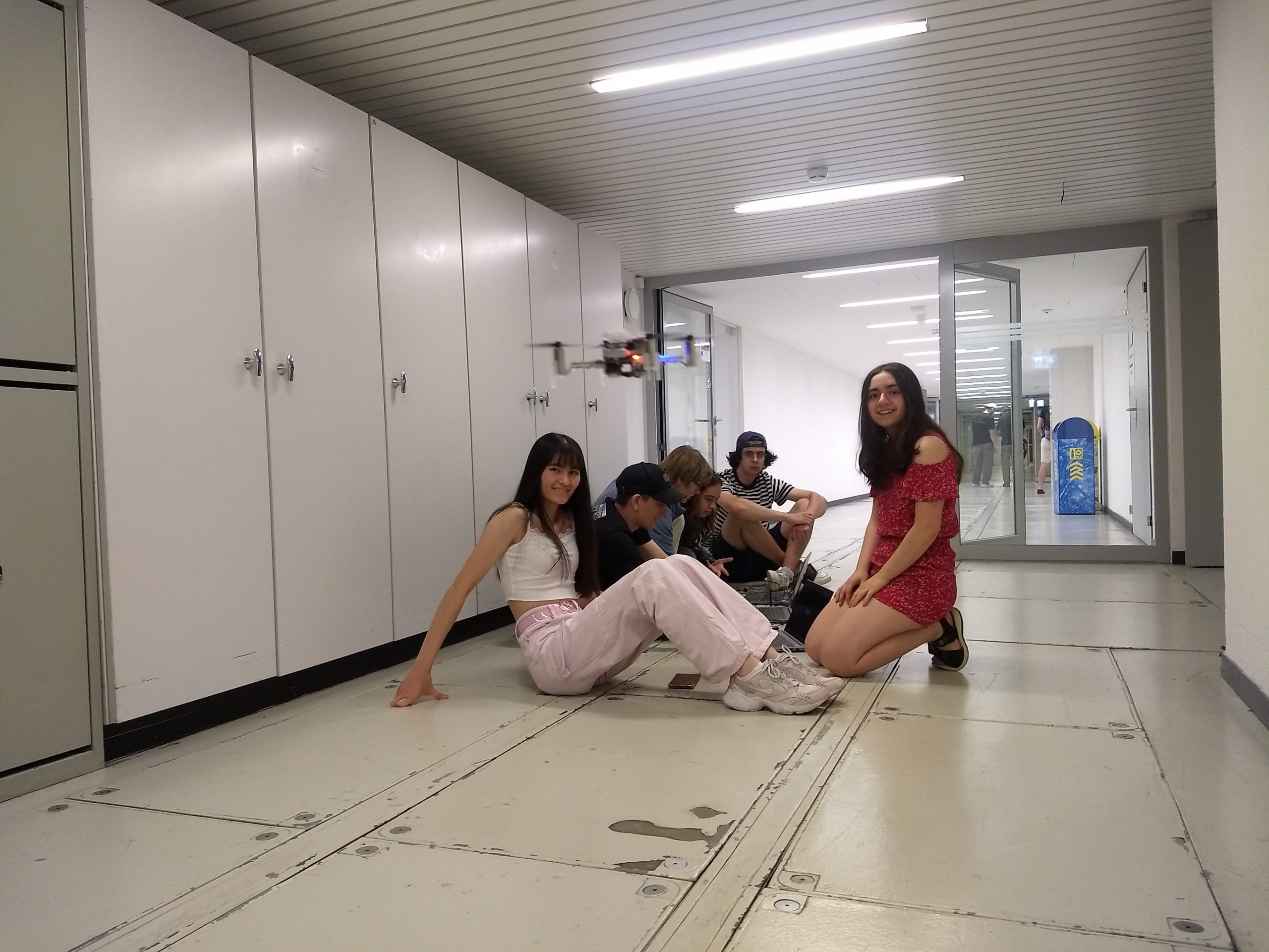
In the end, we saw many cool projects, from a song played as a canon on multiple motors to a transporter drone, flying successfully through the gate, doing a successful looping (unfortunately no successful landing yet…), racing against each other (possibly with disco-lights on the deck) and trials for reaching max speed in the hallway.

The hallway was very popular to fly, as the distance to accelerate was longer…
Practice on the race parkour

The most popular base project was to steer the drone with the keyboard – unfortunately (or fortunately? they sure had fun with it once it was running and they might have learned enough in the remaining week…), this was very easy after we showed them where Marcus’ script lives (here) and which 8 lines (170-177) they have to remove for it to work without an AI-deck (and don’t forget to adapt the URI)…

Friday

Quite an audience!
Flying was forbidden – but playing music with motors was not!

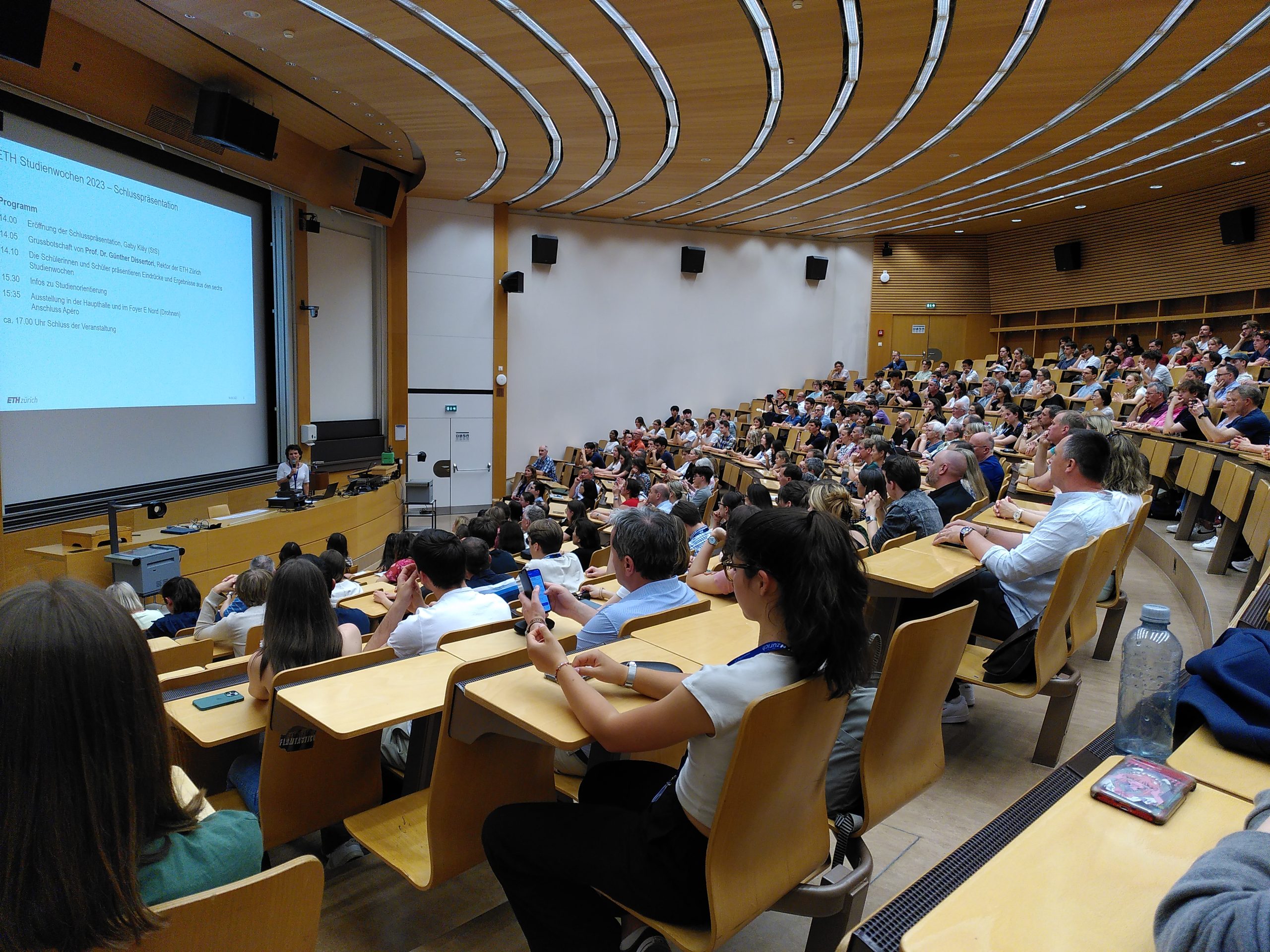
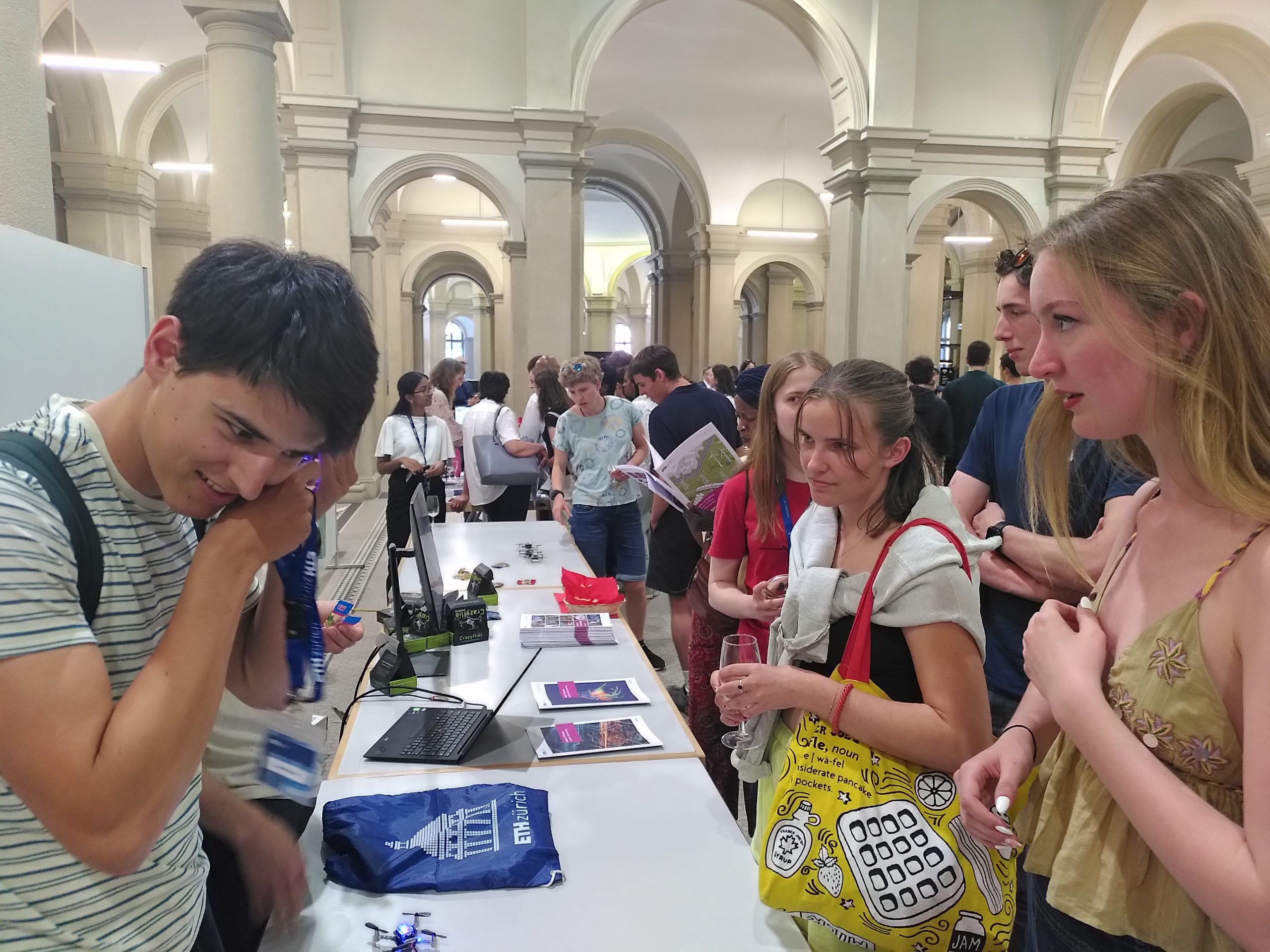
On Friday it was presentation day – in the morning they could still work on their projects, but in the afternoon all the 120 students (and most of their parents) came together in a huge lecture hall to present what they did during this week. And, as at a real conference, they had posters and their drones (which we, unfortunately, were not allowed to fly without a fireproof net… Will organize this next time) to show their projects to family, friends, and even random tourists (the entrance hall of the ETH main building is on many sightseeing tours).

At the end of the week I doubted the robustness of Crazyflies for a moment – however, Monday morning once I had peace and quiet once again I figured out what was wrong with all hardware which ended up on the “not working for unknown reasons” stack in less than an hour (and fixed almost all of it). Notes to all others and my future self for the next time I give 10 drones to 20 teenagers:

  • If you show them how to tune a PID, also explain that “persistent” means exactly what it says – if you mess up the PID values and persist them they will stay this way until you reset them, no matter how often you reflash the drone.
  • Explain how fragile connectors are and that you NEVER should pull at cables. Also, mention 10x more to be careful when plugging in decks. And radios.
  • Keep one “private” drone no one is allowed to mess with – it will help greatly to figure out if they only broke the flow deck connectors or something more serious (which actually never happened)
  • Doing only warm boots with setting individual addresses with the CLOAD_CMDS while flashing saved us a lot of trouble, randomly connecting to drones only happened once they discovered the app for the phone…

The coding tasks (and at least some minimal solutions) can be found on my fork: Tasks and solutions. They are kept short on purpose – we at the Center for Project-Based Learning believe in our name – we believe the most learning (and fun) happens when you rather freely explore what you can do with the basic tools you just learned.

P.S. For completeness – I cut out all the parts which really had nothing to do with Crazyflies, we also did lab tours in the high-voltage laboratory and the laboratory for optical communication – and of course had some social events with actual university students. As much as we like the Crazyflie, even we have to admit that the field of electrical engineering is even bigger than what we can show with those tiny drones ;)

A big part of our work is to provide examples, getting-started guides and other documentation to get users started quickly. Documentation should be up-to-date, be understandable and detailed but, at the same time, not overwhelming. Examples should cover common applications and, most importantly, teach how to create your own projects. This is a never-ending task as our eco-system constantly evolves.

In recent weeks we have updated many parts of the AI-deck documentation and examples – this process is not finished (and will never be), but we thought giving you an overview about what we think most struggle with as well as what we updated would be interesting – especially as we see many AI-deck related questions in the discussions.
We saw that many struggle with understanding the whole communication chain and the importance to update all microcontrollers in it – so we will first give an overview on how everything is connected and then dive into where to find documentation, which examples already exist and how to get started with an own project on GAP8. Note that this post is centered around the GAP8; we do not go into detail about the NINA WiFi.

Here we go:

How does the AI-deck fit into the Crazyflie Eco-System? How does it communicate?

As with all other decks, the AI-deck is connected over expansion headers. It gets power directly from the battery (VCOM), and both microcontrollers (GAP8 and the NINA WiFi module) are connected to the STM32 via UART.

AI-deck expansion header connections.

To send messages between all those microcontrollers, the CPX protocol was introduced. As the NINA and GAP8 are also connected (via SPI), we have redundant information paths – so per definition, we always route over the NINA.

Now how can we send code to the GAP8 for it to run?

GAP8 always executes code from L2 (second-level RAM), as it has no internal flash. However, it can load code into L2 over a HyperBus interface from external flash memory on startup (which it does if a fuse is blown, however this is already done on your AI-deck and out of scope here). As GAP8 has only volatile memory, it must always load code from exactly the same flash address. To make it possible to update applications easily, we implemented a bootloader, a minimal program which is the first thing to run on startup. The bootloader can either update the application code in flash or copy it into L2, and, if the code is valid, run it. Why is this easier? First, you don’t need to connect a programmer, as the bootloader can read data over other peripherals (in our case SPI from the NINA module). Second, it is safer – if the update fails (and you, for some reason, end up with random code where your application should be) the firmware code will not be valid (the hash computation will fail) and GAP8 will not jump to the corrupt application code but instead safely stay in the bootloader.

As the chain for the over-the-air update with the bootloader is rather complex, we illustrate the ways to flash GAP8 in the image below.

  • the blue path illustrates how you can program over JTAG – you can either write code directly into L2 to run it (this is volatile memory, the code will disappear if you power cycle) or you can write it into flash (over GAP8), such that it is loaded on startup (if you overwrite the bootloader, not recommended) or with the bootloader.
  • the red path is using the cfloader. Meaning it sends your code over the Crazyradio to the nRF, then further to the STM32, from there to the ESP32 (the NINA WiFi module) and from there to the GAP8. This path uses CPX messages; you can read more about it in the CPX documentation.
System Architecture of a Crazyflie with an AI-deck connected.

Where is the documentation?

We have tutorials as well as repository documentation. Tutorials guide you through all the steps needed to run a specific example, while the repository documentation aims to document the general infrastructure and examples in more detail (but without all not directly related steps such as flashing a bootloader, updating other firmware, etc.).

So when you use your AI-deck for the first time, you should start with the getting started guide.
Then you are most likely interested in a more detailed explanation about the used infrastructure, such as the GAP8 including the SDK, how to flash, which examples exist and how to run them, etc. So now you should check out the repository documentation.

As we are mostly speaking about GAP8 here, we should also mention that there is of course also documentation for it outside of Bitcraze. GAP8 is produced by Greenwaves, who provides references and has a public SDK on github – meaning one can actually look up the code for all drivers, look at open issues or even contribute with pull-requests.

Which examples exist? What are they there for? What did we update?

This example is there to get you started with your own applications – it provides a minimal implementation of how to send something to the cfclient console from the GAP8 and is explained in detail in the next section of this post.

The camera test is, as it says, to test the camera – however, it sends the image over JTAG, so if you don’t have a debugger and/or don’t want to overwrite the bootloader this is not an example for you.

The most classic example – this example is used in the getting started guide and streams video over WiFi.

This example uses filters to find faces in images – be a bit careful, though, as it is very sensitive to noisy backgrounds and, for example, blonde hair. However, along with nice image processing examples, it now also implements the streaming of the images in configurable resolution, a fun feature we recently added!

The classification demo is our AI demo which recognizes parcels. Here we recently fixed the CPX initialization, so it can again send results to the console in the cfclient!

The send character over UART example was neither updated nor tested with the newest docker (yet).

How do I write my own code on gap8?


Now we’ll walk you through a minimal example of how to send Hello World from GAP9 to the cfclient console.

C Code

We start with the main file (which we called hello_world_gap8.c and is found here) by including some dependencies:

#include "pmsis.h" for the drivers

#include "bsp/bsp.h" for some configuration parameters (pad configurations for connecting to memory, camera, etc.)

#include "cpx.h" for using the CPX functions to send our hello world to the console

Then we have to write our main function:

int main(void)
{
  return pmsis_kickoff((void *)start_example);
}Code language: JavaScript (javascript)

We call pmsis_kickoff() to start the scheduler and an event kernel, giving it a pointer to the function we want to execute.
This function is what we write next (insert it above the main function, such that it is found in the code of the main).

void start_example(void)
{
  pi_bsp_init();
  cpxInit();

  while (1)
  {
      cpxPrintToConsole(LOG_TO_CRTP, "Hello World\n");
      pi_time_wait_us(1000*1000);
  }

}Code language: JavaScript (javascript)

First we need to initialize the pads according to our configuration (the configuration is automatically chosen with sourcing the ai_deck.sh, which is automatically done in the docker) with pi_bsp_init().
Then we need to initialize CPX (which initializes for example the SPI connection to the NINA WiFi), to be able to send CPX packets. You find more information in the CPX documentation.
Now we are ready for our while loop, in which we want to send “Hello World” to the console (called LOG_TO_CRTP). To not keep the busses overly busy we only want to send it every second, so we wait before we repeat.

Makefile

The Makefile is hierarchical – meaning we have hidden files that do most of the work and need to include $(RULES_DIR)/pmsis_rules.mk in the last line of the Makefile.

We start with defining where the io should go – possibly are host or uart (this is actually not used in this example, but if you’d add a printf, this would define where it goes).
Then we define the operating system we want to use – we can use pulpos or freertos. We chose this as freertos is way more advanced (we are paying for this with some overhead, but in most cases, it will be worth it).

io=uart
PMSIS_OS = freertos

In the next step we need to set the name of our application (this defines the file names of the build output), include the sources (meaning our main c file as well as the two c files CPX needs) and include the header files directory (header files in the same directory as the Makefile should automatically found, but our CPX header files are in a library directory). Make sure all the relative paths are correct for your folder structure.

APP = hello_world_gap8
APP_SRCS += hello_world_gap8.c ../../../lib/cpx/src/com.c ../../../lib/cpx/src/cpx.c
APP_INC=../../../lib/cpx/inc

As a last step, we want to set some compiler flags. Firstly, we want to compile optimized, so we add -O3. Then we add -g to embed debug information.
As we use timers for CPX we also need to add two additional defines to ensure all functions we need are included: the configUSE_TIMERS=1 and the INCLUDE_xTimerPendFunctionCall=1 defines.

APP_CFLAGS += -O3 -g
APP_CFLAGS += -DconfigUSE_TIMERS=1 -DINCLUDE_xTimerPendFunctionCall=1

Compile and Flash


For this section we assume you are in the ai-deck-examples directory.

Now we want to compile using docker:

docker run --rm -v ${PWD}:/module --privileged bitcraze/aideck tools/build/make-example SRC_DIR clean allCode language: JavaScript (javascript)

Where SRC_DIR is the location of your code, here it is examples/other/hello_world_gap8.

Note: You don’t always need to “clean” if you don’t modify the Makefile. It should be fine to save some time by skipping this.

And finally we want to flash using the OTA updater:

cfloader flash [binary] deck-bcAI:gap8-fw -w CRAZYFLIE_URICode language: CSS (css)

Where in this example, [binary] has to be replaced with examples/other/hello_world_gap8/BUILD/GAP8_V2/GCC_RISCV_FREERTOS/target.board.devices.flash.img, and the CRAZYFLIE_URI is something like radio://0/80/2M/E7E7E7E7E7.

Now you can connect to your drone with the cfclient and should see a CPX: GAP8: Hello World print every second.

Note: The LED will not blink as in most other examples, as we did not implement a task which does this.

We hope this blog post helps you get started with your own awesome applications faster!

My name is Hanna, and I just started as an intern at Bitcraze. However, it is not my first time working with a drone or even the Crazyflie, so I’ll tell you a bit about how I ended up here.

The first time I used a drone, actually even a Crazyflie, was in a semester thesis at ETH Zurich in 2017, where my task was to extend a Crazyflie with a Parallel Ultra Low-Power (PULP) System-on-Chip (SoC) connected to a camera and external memory. This was the first prototype of the AI-deck you can buy here nowadays (as used here) :)

My next drone adventure was an internship at a company building tethered drones for firefighters – a much bigger system than the Crazyflie. I was in charge of the update system, so more on the firmware side this time. It was a very interesting experience, but I swore never to build a system with more than three microcontrollers in it again.

This and a liking for tiny and restricted embedded systems brought me back to the smaller drones again. I did my master thesis back at ETH about developing a PULP-based nano-drone (nano-drones are just tiny drones that fit approximately in the palm of your hand and use only around 10Watts of power, the category Crazyflies fit in) and some onboard intelligence for it. As a starting point, we used the Crazyflie, both for the hardware and the software. It turned out to be a very hard task to port the firmware to a processor with only a very basic operating system at that time. Still, eventually I knew almost every last detail of the Crazyflie firmware, and it actually flew.

However, for this to happen, I needed some more time than the master thesis – in the meantime, I started to pursue a PhD at ETH Zurich. I am working towards autonomous miniaturized drones – so besides the part with the tiny PULP-based drone I already told you about, I also work on the “autonomous” part. Contrary to many other labs our focus is not only on novel algorithms though, we also work with novel sensors and processors. Two very interesting recent developments for us are a multi-zone Time-of-Flight sensor and the novel gap9 processor, which both fit on a Crazyflie in terms of power, size and weight. This enables new possibilities in obstacle avoidance, localization, mapping and many more. Last year my colleagues and I already posted a blog post about our newest advances in obstacle avoidance (here, with Videos!). More recently, we worked on onboard localization, using novel multi-zone Time-of-Flight sensors and the very new GAP9 processor to execute Monte Carlo localization onboard a Crazyflie (arxiv).

On the left you see an example of a multi-zone Time-of-Flight image (the background is a picture from the AI-deck), from here. On the right you see our prototype for localization in action – from our DATE23 paper (arxiv).

For me, localizing with a given map is a fascinating topic and one of the reasons I ended up in Sweden. It is one of the most basic skills of robots or even humans to navigate from A to B as fast as possible, and the basis of my favourite sport. The sport is called “orienteering” and is about running as fast as possible to some checkpoints on a map, usually through a forest. It is a very common sport in Sweden, which is the reason I started learning Swedish some years ago. So when the opportunity to go to Malmö for some months to join Bitcraze presented itself, I was happy to take it – not only because I like the company philosophy, but also because I just like to run around in Swedish forests :)

Now I am looking forward to my time here, I hope to learn lots about drones, firmware, new sensors, production, testing, company organization and to meet a lot of new nice people!

Greetings from Malmö – it can be a bit cold and rainy, but the sea and landscape are beautiful!

Hanna

This weeks guest blog post is from Hanna Müller, Vlad Niculescu and Tommaso Polonelli, who are working with Luca Benini at the Integrated Systems Lab and Michele Magno at the Center for Project-Based Learning, both at ETH Zürich. Enjoy!

This blog post will give you some insight into our current work towards autonomous flight on nano-drones using a miniaturized multi-zone depth sensor. Here we will mainly talk about obstacle avoidance, as it is our first building block towards fully autonomous navigation. Who knows, maybe in the future, we will have the honor to write another blog post about localization and mapping ;)

A Crazyflie 2.1 with our custom multi-zone ToF deck, a flow deck and a vicon marker.

Obstacle avoidance on nano-drones is challenging, as the restricted payload limits on-board sensors and computational power. Most approaches, therefore, use lightweight and ultra-low-power monocular cameras (as the AI-deck) or 1d depth sensors (as the multi-ranger deck). However, both those approaches have drawbacks – the camera images need extensive processing, usually even neural networks to detect obstacles. Neural networks additionally need training data and are prone to fail in completely new scenarios. The 1d depth sensors can reliably detect obstacles in their field of view (FoV); however, no information about the size or exact position of the obstacle is obtained.


On bigger drones, usually lidars or radars are used, but unfortunately, due to the limited weight and power consumption, those cannot be carried and used on nano-drones. However, in 2021 STMicroelectronics introduced a new multi-zone Time-of-Flight (ToF) sensor – with maximal 8×8 pixel resolution, a range up to 4m (according to the datasheet), a small form-factor and low power consumption of only 286mW (typical) it is ideal to use on nano-drones.


In the picture on top, you can see the Crazyflie 2.1 with our custom ToF deck (open-sourced at https://github.com/ETH-PBL/Matrix_ToF_Drones). We described this deck for the first time in [1], together with a sensor characterization. From this, we saw that we could use the sensor in different light conditions and on different colored obstacles, but from 2m on, the measurements started to get incomplete in all scenarios. However, as the sensor can detect invalid measurements (due to interference or obstacles being out of range), we can still rely on our information. In [2], we presented the system and some steps towards obstacle avoidance in a demo abstract, as you can see in the video below:

The next thing we did was to collect a dataset – we flew with different combinations of decks (flow-deck v2, AI-deck, our custom multi-zone ToF deck) and sometimes even tracked by a vicon system. Those recordings amount to an extensive dataset with depth images, RGB images, internal state estimation and the position and attitude ground truth.


We then fed the recorded data into a python simulation to develop an obstacle avoidance algorithm. We focused on only the ToF data (we are not fusing with the camera in this project, we just provide the data for future work). We aimed for a very efficient solution – because we want it to run on-board, on the STM32F405, with low latency and without occupying too many resources. Our algorithm is very lightweight but highly effective – we divide the FoV in different zones, according to how dangerous obstacles in those areas are and then use a decision tree to decide on a steering angle and velocity.


With only using up 0.31% of the computational power and 210 μs latency, we reached our goal of developing an efficient obstacle avoidance algorithm. Our system is also low-power, the power to lift the additional sensor with all accompanying electronics as well as the supply of it totals in less than 10% of the whole drone. On average, our system reaches a flight time of around 7 minutes. We refer to our preprint [3] for details on our various tests – they include flights with distances up to 212 m and 100% reliability and high agility at a low speed in an office environment.

As our paper is currently submitted but not yet accepted our code and dataset are not yet released – however, the hardware design is already accessible: https://github.com/ETH-PBL/Matrix_ToF_Drones

[1] V. Niculescu, H. Müller, I. Ostovar, T. Polonelli, M. Magno and L. Benini, “Towards a Multi-Pixel Time-of-Flight Indoor Navigation System for Nano-Drone Applications,” 2022 IEEE International Instrumentation and Measurement Technology Conference (I2MTC), 2022, pp. 1-6, doi: 10.1109/I2MTC48687.2022.9806701.
[2] I. Ostovar, V. Niculescu, H. Müller, T. Polonelli, M. Magno and L. Benini, “Demo Abstract: Towards Reliable Obstacle Avoidance for Nano-UAVs,” 2022 21st ACM/IEEE International Conference on Information Processing in Sensor Networks (IPSN), 2022, pp. 501-502, doi: 10.1109/IPSN54338.2022.00051.
[3] H.Müller, V. Niculescu, T. Polonelli, M. Magno and L. Benini “Robust and Efficient Depth-based Obstacle Avoidance for Autonomous Miniaturized UAVs”, submitted to IEEE, preprint: https://arxiv.org/abs/2208.12624