Today we welcome Sam Schoedel and Khai Nguyen from Carnegie Mellon University. Enjoy!
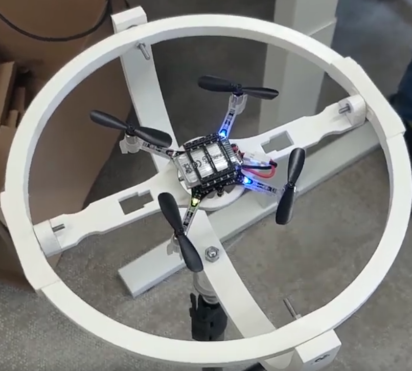
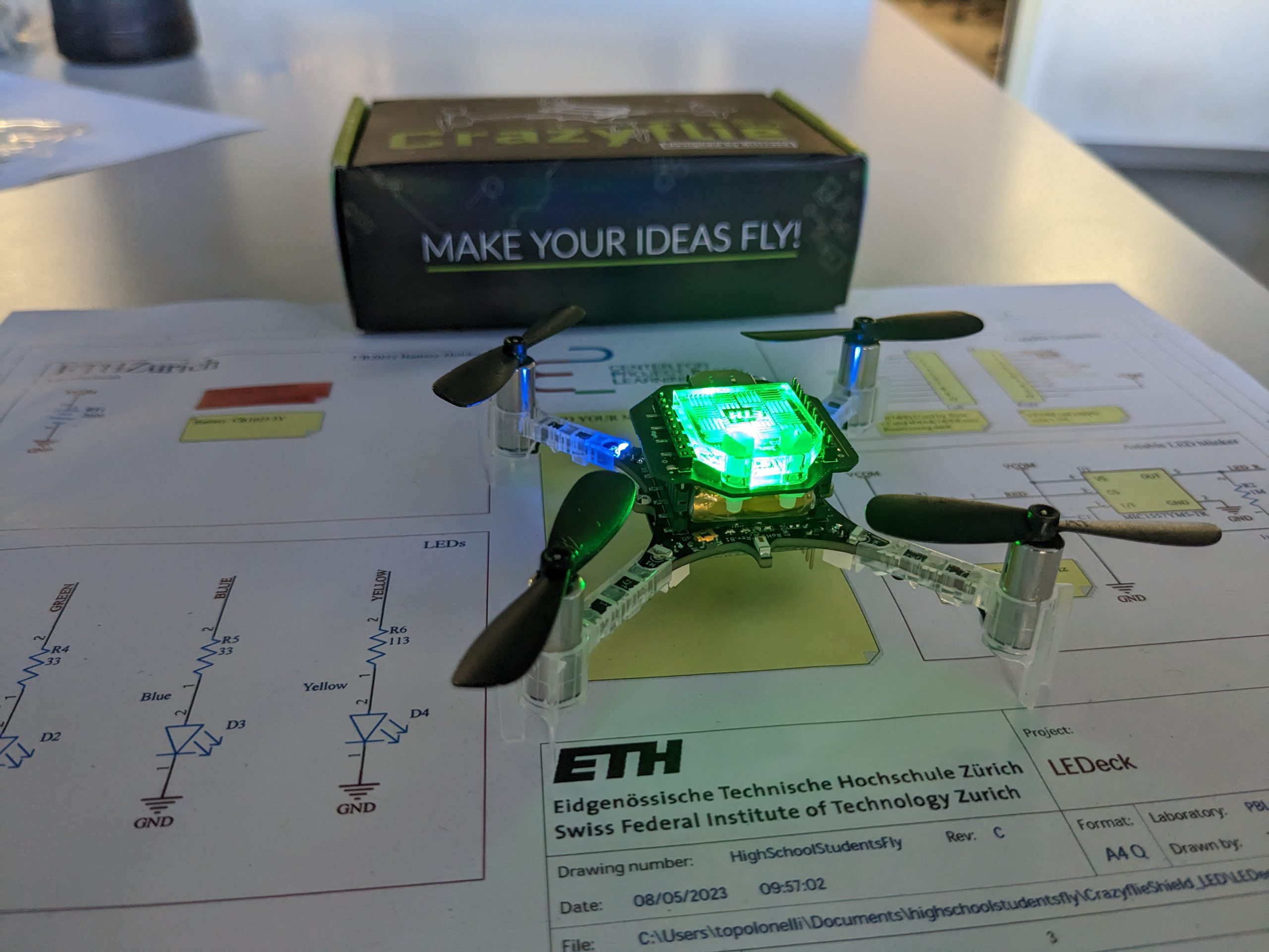
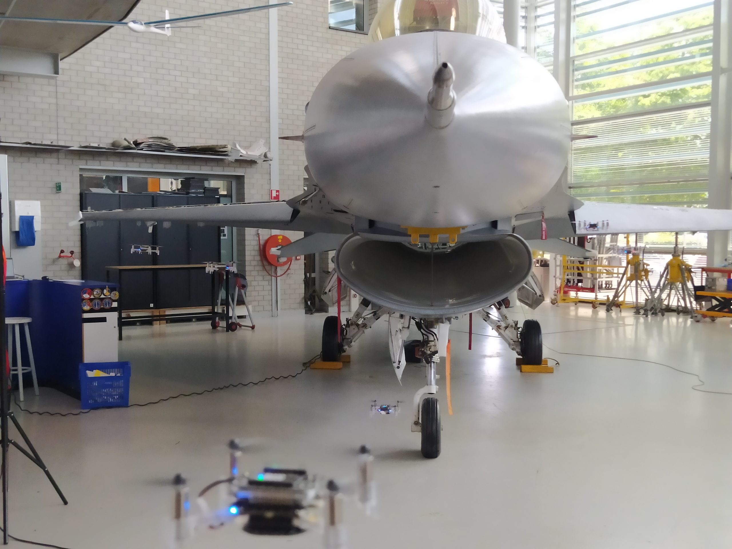
We’re excited to share the research we’ve been doing on model-predictive control (MPC) for tiny robots! Our goal was to find a way to compress an MPC solver to a size that would fit on common microcontrollers like the Crazyflie’s STM32F405 while being fast enough to control the higher frequency dynamics of smaller robots. We came up with a few tricks to make that happen and dubbed the resulting solver TinyMPC. When it came time for hardware experiments, using the Crazyflie just made sense. A tiny solver deserves a tiny robot.
Motivation
Model predictive control is a powerful tool for controlling complex systems, but it is computationally expensive and thus often limited to use cases where the robot can either carry enough computational power or when offboard computing is available. The problem becomes challenging to solve for small robots, especially when we want to perform all of the computation onboard. Smaller robots have inherently faster dynamics which require higher frequency controllers to stabilize, and because of their size they don’t have the capacity to haul around as much computational power as their larger robot counterparts. The computers they can carry are often highly memory-constrained as well. Our question was “how can we shrink the computational complexity and memory costs of MPC down to the scale of tiny robots?”
What We Did
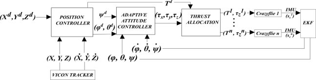
We settled on developing a convex model predictive control solver based on the alternating direction method of multipliers. Convex MPC solvers are limited to reasoning about linear dynamics (on top of any other convex constraints), but have structure that TinyMPC exploits to solve problems efficiently. The tricks we used to achieve this efficiency are described in the paper, but it boils down to rewriting the problem as a constrained linear-quadratic regulator to reduce the memory footprint and then precomputing as many matrices as possible offline so that online calculations are less expensive. These tricks allowed us to fit long-time horizon MPC problems on the Crazyflie and solve them fast enough for real-time use.
What TinyMPC Can Do
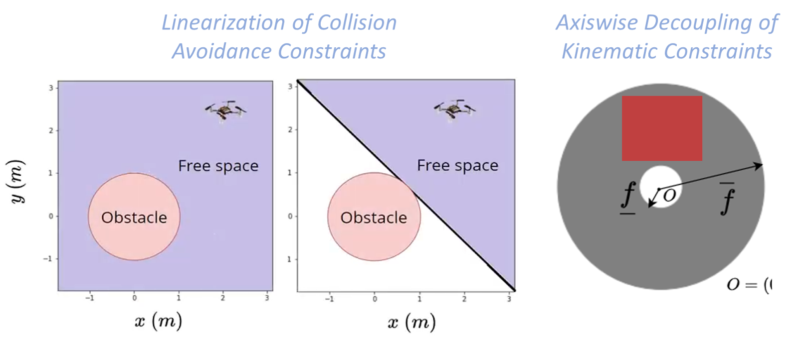
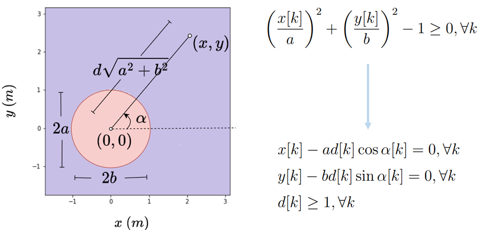
We decided to demonstrate the constraint-handling capabilities of TinyMPC by having the Crazyflie avoid a dynamic obstacle. We achieved this by re-computing hyperplane constraints (green planes in the first video) about a spherical obstacle (transparent white ball) for each knot point in the trajectory at every time step, and then by solving the problem with the new constraints assuming they stayed fixed for the duration of the solve.
In the two videos below, the reference trajectory used by the solver is just a hover position at the origin for every time step. Also, the path the robot takes in the real world will never be exactly the same as the trajectory computed by the solver, which can easily result in collisions. To avoid this, we inflated the end of the stick (and the simulated obstacle) to act as a keep-out region.
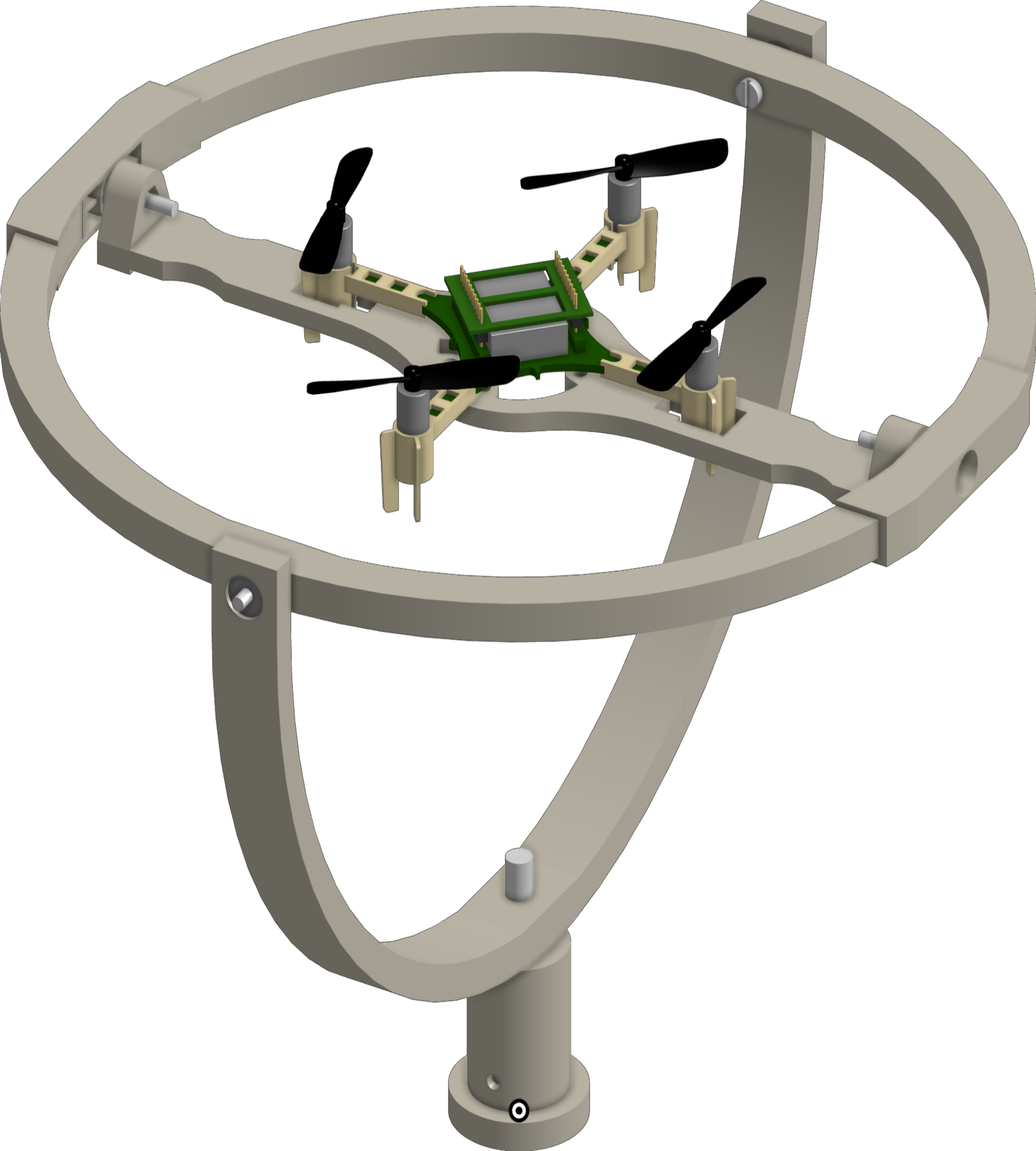
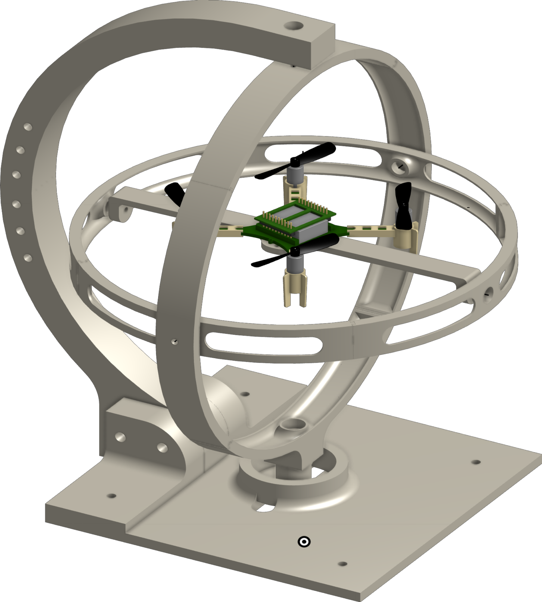
TinyMPC is restricted to reasoning about linear dynamics because of its convex formulation. However, a simple linearization can be taken pretty far. We experimented with recovering from different starting conditions to push the limits of our linear Crazyflie model and were able to successfully recover from a 90 degree angle while obeying the thrust commands for each motor.
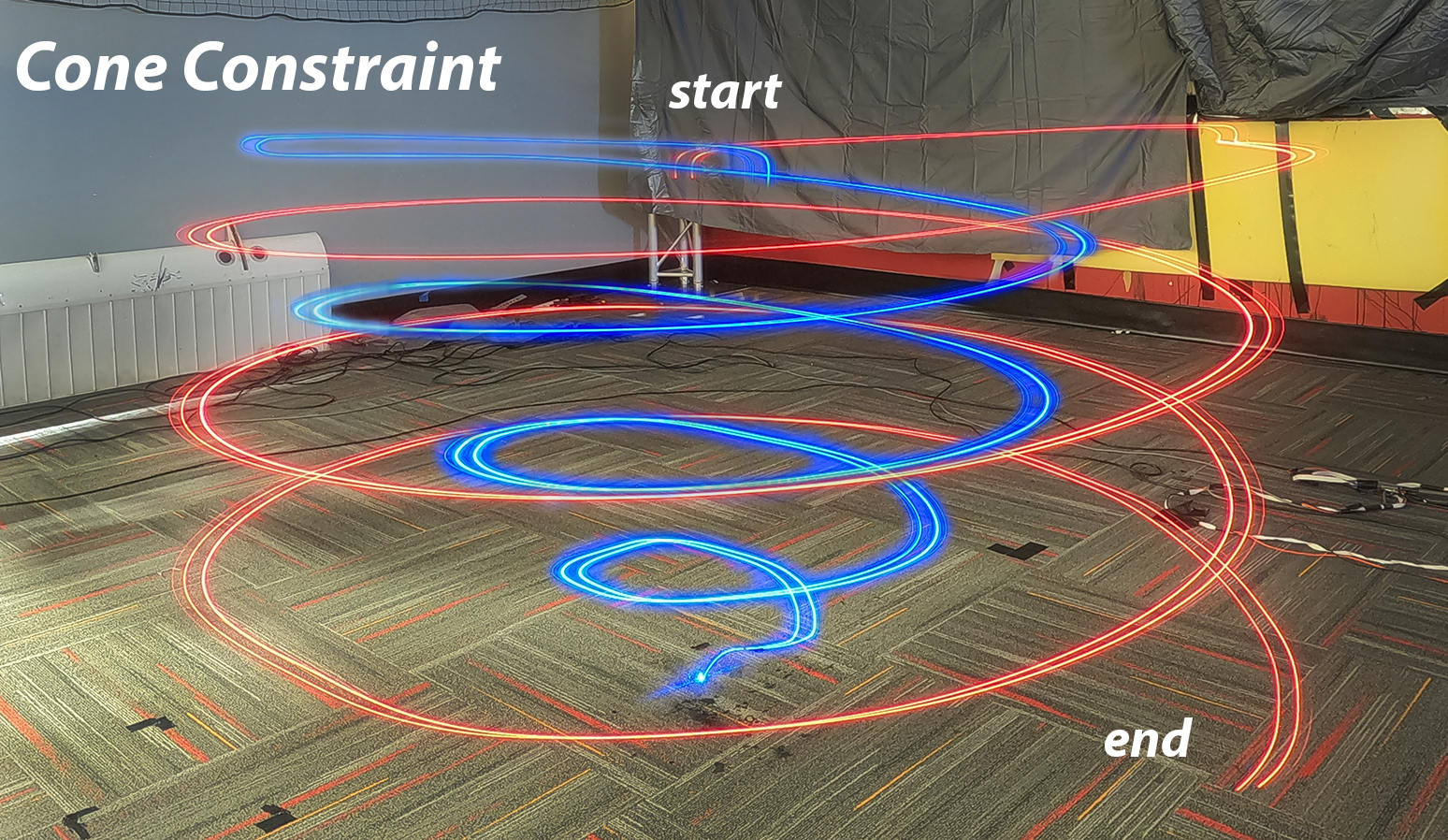
We recently added support for second-order cone constraints as well. These types of constraints allow TinyMPC to reason about friction and thrust cones, for example, which means it can now intelligently control quadrupeds on slippery surfaces and land rockets. To clearly demonstrate the cone constraint, we took long exposure photos of the Crazyflie tracking a cylindrical landing trajectory without any cone constraints (red) and then with a spatial cone constraint that restricts the landing maneuver to a glide slope (blue).
How To Use TinyMPC
All of the information regarding the solver can be found on our website and GitHub org (which is where you can also find the main GitHub repository). TinyMPC currently has a Python wrapper that allows for validating the solver and generating C++ code to run on a robot, and we have a few examples in C++ if you don’t want to use Python. Our website also explains how to linearize your robot and has some examples for setting up the problem with a linear model, solving it an MPC loop, and then generating and running C++ code.
Most importantly to the Crazyflie community, our TinyMPC-integrated firmware is available and should work out of the box. Let us know if you use it and run into issues!
Our accompanying research papers:
Khai Nguyen, Sam Schoedel, Anoushka Alavilli, Brian Plancher, and Zachary Manchester. “TinyMPC: Model-Predictive Control on Resource-Constrained Microcontrollers.” arXiv preprint arXiv:2310.16985 (2023). https://arxiv.org/pdf/2310.16985
Sam Schoedel, Khai Nguyen, Elakhya Nedumaran, Brian Plancher, and Zachary Manchester. “Code Generation for Conic Model-Predictive Control on Microcontrollers with TinyMPC.” arXiv preprint arXiv:2403.18149 (2024). https://arxiv.org/pdf/2403.18149
We would love your feedback and suggestions, and let us know if you use TinyMPC for your tiny platforms!