Flying formations with a swarm is always fun to develop and watch, but it is also a great way to stress-test the software behind it. As part of the development of cflib2, we put it through one of its toughest tests yet: flying 49 Crazyflies in coordinated formations.
The entire swarm was controlled using a single Crazyradio 2.0, highlighting the combined improvements in cflib2 and Crazyradio firmware over the past few months.
The setup
The hardware configuration was relatively straightforward. We used 49 Crazyflie 2.1 Brushless drones, each one equipped with a bottom-mounted Color LED deck for vivid lighting effects. For positioning, we used the Lighthouse positioning system, covering the entire flight area, which was roughly 5x5x2m. Its accuracy allowed the Crazyflies to fly grid formations with just 0.4m spacing between them.
One of the big practical challenges when managing a large swarm is swapping the depleted batteries for charged ones. Thanks to the Crazyflie 2.1 Brushless PCB design, each drone can now charge while sitting on its charging dock, making it much easier to prepare the swarm for the next flight.
Flying the formations
The swarm performed a sequence of synchronized formations under the control of a central PC. Rather than streaming the full trajectories to every drone, the formations are built using the Crazyflie’s High-Level Commander. Each Crazyflie receives simple motion commands such as go to or spiral, and executes the corresponding trajectory onboard. At the same time, it receives commands for changing the color of the Color LED deck.
Using cflib2, these commands can be sent to all 49 Crazyflies through a singe Crazyradio 2.0, which was not possible with cflib.
Looking ahead
This demonstration is an exciting milestone for cflib2 and showcases what the new library makes possible. While controlling 49 Crazyflies is an impressive demonstration, cflib2 is designed to benefit projects of every size. Whether you are flying a single Crazyflie or coordinating a large swarm, the goal is to provide a faster, more scalable, and more robust communication library.
Most of the functionalities from cflib have already been migrated to cflib2, and development is continuing. For many applications, cflib2 is already ready to use, so if you would like to try it out, you can find the repository here.
ICRA 2026 has wrapped up, and we’re back from a fantastic week in Vienna! Booth 91 was busy from start to finish, and we wanted to put together a short highlight video to share some of what happened — for everyone who stopped by, and for everyone who couldn’t make it this year.
The Swarm Demo
At the center of our booth was our live autonomous swarm demo — multiple Crazyflies flying autonomously in a controlled indoor environment, with everything tracked, repeatable, and stable across runs. We also could play around with our Lighthouse wand – which was also a great solution for troubleshooting the few misbehaving drones we had during those 3 days.
SwarmGPT, Live and Interactive
One of the highlights of the week was demonstrating SwarmGPT together with the Learning Systems and Robotics Lab (LSY) at the Technical University of Munich. SwarmGPT explores a simple but powerful idea: instead of hand-coding trajectories, you describe the intent — pick a piece of music, prompt a style or expression — and the system handles the planning and safety while the swarm performs it.
This time around, we brought a more interactive version of the demo than our end-of-year collaboration a few months back, and visitors got to try it out for themselves at the booth. Watching people prompt the swarm and then watch their idea come to life in the air was a great reminder of how far natural-language interfaces have come, and how much room there still is to explore in this space.
Research We Saw on the Crazyflie
Beyond our own demos, one of our favorite parts of ICRA is talking with our users and seeing what the community has built. This year was no exception — we spotted Crazyflies appearing in research spanning multi-agent coordination, modular micro-UAVs designed for autonomous mid-air docking, and decentralized swarm control approaches where each drone makes its own decisions based on local information rather than a central planner. Some examples include:
It’s always a bit surreal to see the same small quadcopter we ship from our office end up at the center of such different research questions — from choreography and language-driven control, to docking and modular hardware, to fully decentralized swarms. If you presented work involving the Crazyflie this year, thank you for stopping by and sharing it with us — and if you left a poster behind, it’s already found a home on our office wall.
Thanks for Stopping By
ICRA continues to be one of our favorite events of the year, not just for the demos, but for the conversations. Someone describes a challenge they’re running into in their lab, and a few months later, that conversation has often turned into a feature, a library improvement, or a new piece of hardware. If you stopped by booth 91, told us about your research, or just said hello, thank you. We’re already looking forward to the next one!
If you’d like to dig deeper into any of what’s shown in the video, or want to get started with the Crazyflie yourself, head over to bitcraze.io or reach out at contact@bitcraze.io.
We are at ICRA 2026 in booth 91, and we are looking forward to a few days in Vienna for research discussions, technical conversations, and reconnecting with the community.
ICRA has always been a favorite of ours. It brings together researchers from very different domains, but despite different research goals, many face similar questions around how to build reliable experiments, iterate quickly, and evaluate results in a repeatable way.
Many of the improvements in the Crazyflie ecosystem over the years have started exactly there. Someone stops by the booth, describes a challenge in their lab, and shortly thereafter a feature, library, or hardware addition begins to take shape.
This year we are bringing a few things we are excited to discuss.
Towards larger and easier-to-manage swarms
Over the last months we have spent time improving how larger groups of Crazyflies behave and scale in practice.
Swarm experiments sometimes start small. Then a few drones become ten, ten become fifty, and suddenly radio communication and system overhead become part of the research problem itself.
Recent work around overall system performance has significantly improved how many Crazyflies can be handled from a single radio, reducing communication bottlenecks and making larger coordinated experiments easier to run. We are also working toward improved tooling and workflows for managing swarms, with the goal of reducing setup complexity and making experiments easier to reproduce. A transition to Rust has helped reduce connection overhead and improve responsiveness in larger systems.
We are looking forward to discussing where this work is heading and hearing what challenges researchers encounter in their own systems.
Tech talk: “A Swarm Welcome to New Aerial Robotics Functionality”
Wednesday, June 3rd, 12:45 CEST, at the Tech Talk Stage in Hall C7
We will give a tech talk focused on recent work around swarm functionality and capabilities.
The session will cover improvements that significantly expand what can be done with larger Crazyflie groups and how recent developments are reducing practical limitations in swarm experimentation.
If your work involves multi-agent systems, collective behaviors, or coordinated aerial robotics, stop by and continue the discussion afterward.
Demonstration: SwarmGPT and human interaction with robot swarms
Some of you may remember the end-of-year collaboration a few months ago. This time we are bringing a more interactive version of the concept. SwarmGPT explores how natural-language intent can be translated into coordinated swarm behaviors. Rather than manually programming trajectories, users can pick a piece of music and prompt desired expression, and leave planning and safety mechanisms to the system to execute on.
Come by our booth and try it for yourselves.
Color, Rust, camera deck, and more
We will also bring several smaller developments and ongoing efforts that we have discussed on the blog over recent months.
Discussions around improved swarm workflows and management support
The Color LED deck has turned out to be useful far beyond aesthetics. In swarm experiments, visible state information can help indicate timing, grouping, synchronization, and system behavior across multiple agents.
User survey
We will be running a community survey during ICRA. One of the strengths of the Crazyflie ecosystem is the breadth of research and experimentation happening around it. People use the platform in ways we never originally anticipated, often combining different hardware, software, and workflows depending on the research problem they are trying to solve.
The survey is an opportunity for us to better understand how the platform is being used today, and the feedback helps us make better decisions around priorities, tooling, documentation, hardware, and long-term roadmap direction.
This has become a tradition. If you are presenting research involving Crazyflie and do not need your poster after your session, bring it by the booth.
We love collecting them and filling our office walls with the incredible range of work built on the platform. It is also one of our favorite ways of seeing where the community takes the Crazyflie next.
Bring your poster, and we will make sure you leave with a little Bitcraze treat in return.
Find us in booth 91
If you are working with Crazyflie already, considering it for your research, or simply want to discuss ideas around swarm robotics, autonomous flight, perception, AI, or experimental workflows, stop by booth 91.
Some Fun-Friday projects begin with a clear goal and a straight path to the finish line. The best ones, however, take you somewhere completely unexpected.
This project originally set out to build a device for determining spatial coordinates within a Lighthouse-covered flight area. Instead, it evolved into the Lighthouse Wand, a hand-held “magic wand” letting you grab and move drones in 3D space just by pointing at them.
How it works
The Wand is a Crazyflie platform with a Lighthouse positioning deck. That’s enough for it to know its own position and orientation in the room. When the button is pressed, it starts broadcasting those 6 numbers over Peer to Peer radio.
Any Crazyflie/receiver in the room on the same radio channel, listens to those packets and runs a simple “grasping” algorithm: while the wand line (positive x-axis) passes close enough to the drone, it builds up a confidence score. Once the score crosses a threshold, the drone is considered grasped. From that point on, it just keeps a specific distance from the wand, while being on the wand line.
When the button is released, the grasped drone either hovers in place, or lands, depending on the release height.
The Color LED deck on the receiver drone, gives you visual feedback: yellow while the Crazyflie is building up its confidence score, green when it’s grasped, and red when it’s landing.
A big advantage of this system is that all interactions run entirely onboard the Crazyflies, allowing them to operate without relying on the cfclient or cflib during flight.
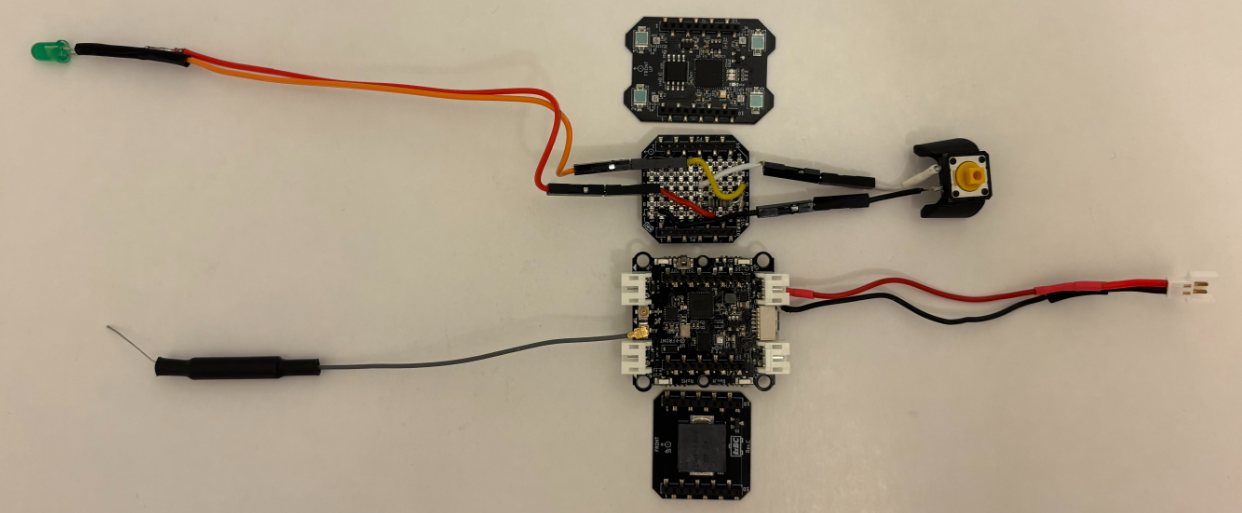
The hardware design
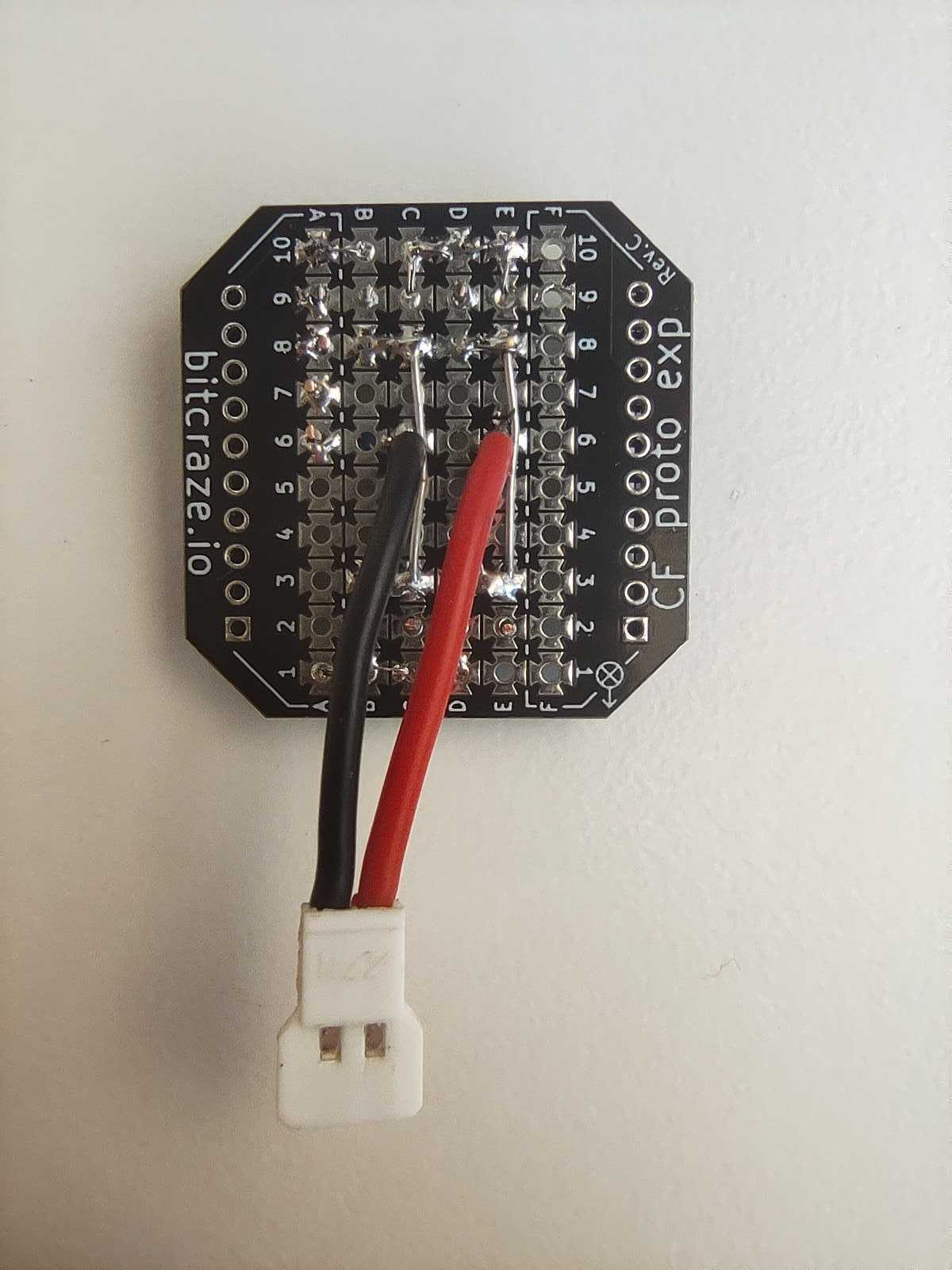
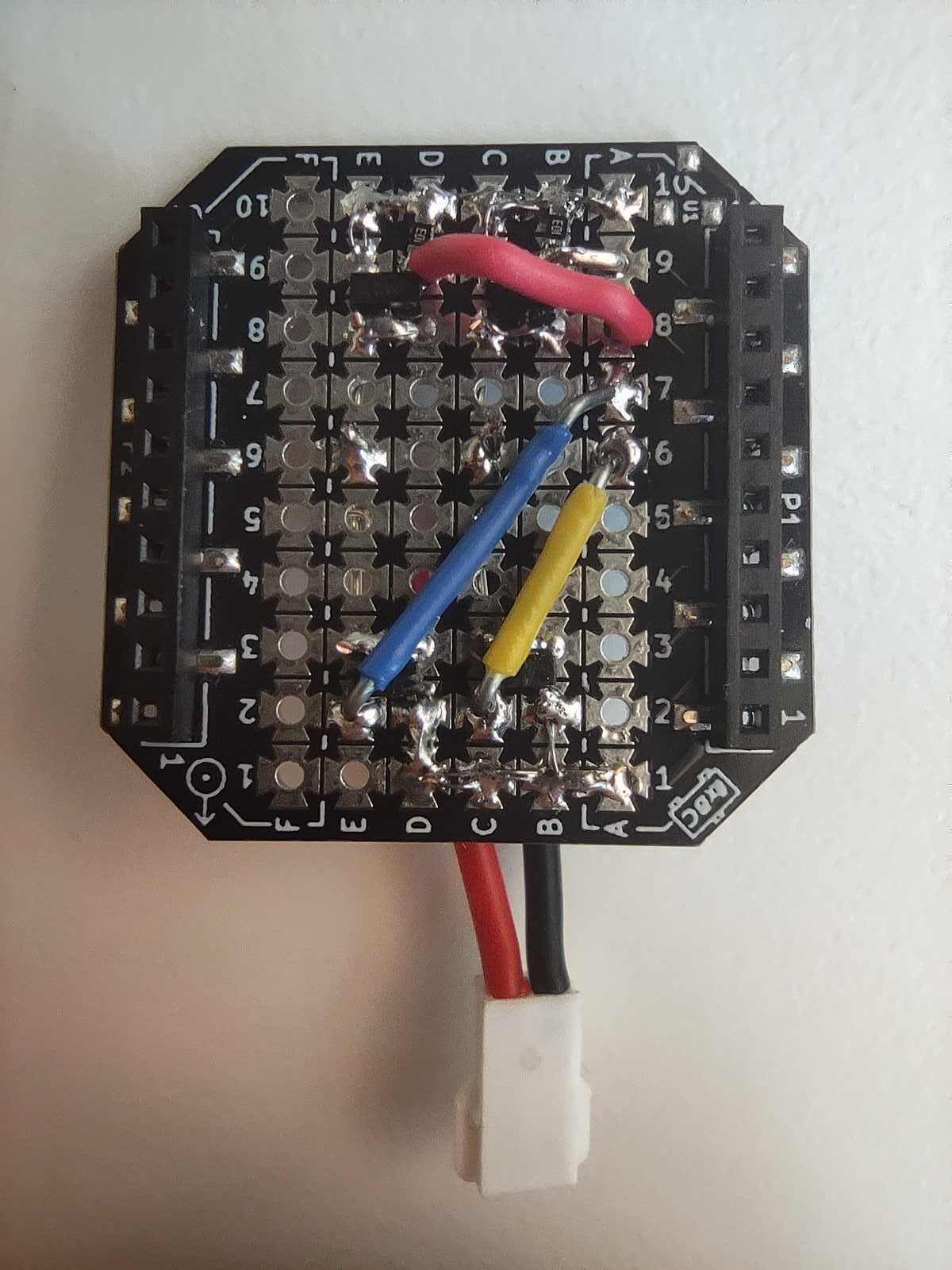
The wand is a Crazyflie Bolt 1.1 with a Lighthouse positioning deck and a Buzzer deck for audio feedback. To allow for user input, I created a simple “Button deck” based on the Prototyping deck utilizing the GPIO pins of the Crazyflie. It also includes an LED for visual feedback when the button is pressed.
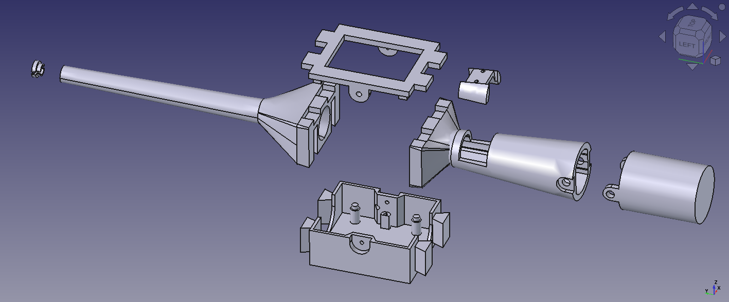
The casing is fully 3D printed in PLA and was designed to give the device a more wand-like feel in the hand. Its shape also makes it easier to hold, aim, and use intuitively during interaction.
The firmware design
Both the Wand and the receiver are firmware apps created on top of the crazyflie-firmware. In the design that I followed, there is a clean separation between the two parties. The wand is a pure broadcaster: it only reads its own pose and transmits it. All grasping logic and flight control run independently on each receiver. Since each receiver is fully autonomous, the system scales to any number of drones with no extra load on the wand.
Where to find the Lighthouse Wand?
A version of the Lighthouse wand is now integrated in our decentralized swarm demo, where it can be used to interact with multiple drones, while the collision avoidance algorithms are still on. This system was first showcased at the European Robotics Forum 2026 in Stavanger, and we’ll also be bringing it to ICRA 2026. If you’re there, stop by booth 91and try flying a bunch of Crazyflies yourself using the wand.
You can find the complete Lighthouse Wand project in this repository. It contains the firmware, the hardware files, and detailed documentation to build and experiment with the wand yourself.
It’s that time of year again! ICRA 2026 (IEEE International Conference on Robotics & Automation) is just around the corner, and this year we’re heading to Vienna. We couldn’t be more excited about this one: Vienna is an incredible city, and we’ve been working on some things we can’t wait to share.
June 1–5, 2026. Come find us!
A reproducible testbed for aerial robotics research
We will be running a live autonomous flight system based on the Crazyflie platform.
The focus is not the flight itself, but what it enables. The system provides a controlled indoor environment where experiments can be repeated, variables isolated, and results compared over time.
This is aligned with how aerial robotics research is actually conducted: iteration speed, reproducibility, and observability matter more than scale in early and mid-stage research. Our platform is designed around those constraints.
Autonomous indoor flight for controlled experimentation
The setup demonstrates autonomous flight under conditions that remain stable across runs.
This allows researchers to evaluate control strategies, perception pipelines, and multi-robot coordination without environmental noise dominating results. It also reduces costs and operational overhead compared to larger platforms, which changes how frequently experiments can be run.
In practice, this makes it feasible to move from idea to validated result faster and with clearer insight into failure modes.
Used in swarm robotics, control, and physical AI research
The Crazyflie platform is used across domains such as swarm robotics, learning-based control, SLAM, and human–robot interaction.
It has been referenced in hundreds of peer-reviewed publications and is often used as a bridge between simulation and larger systems. The value is not in representing the final deployment environment, but in enabling rigorous, comparable experimentation at low cost and risk.
If you are working in these areas, we are interested in how your setup is structured and where constraints appear.
Share your work with us
If you are presenting work that involves the Crazyflie, we would like to see it.
Even better, if you do not need your poster after your session, bring it by the booth! We collect and display these as part of the broader body of work built on the platform. We will make sure it is appreciated properly.
Meet us at ICRA 2026
One of our favourite things about ICRA is getting to meet the community in person, hearing about your research, seeing what you’ve built with the Crazyflie, and exchanging ideas with people who are just as excited about small flying robots as we are. Whether you want to chat about your research, see the demo up close, or just catch up, our booth is the place to be. We love hearing about all the cool projects you’re working on with the Crazyflie, so don’t be shy!
If you are working with the Crazyflie, evaluating platforms, or exploring new research directions, stop by booth 91. You can also reach out at contact@bitcraze.io to schedule time.
This week we wanted to reflect on the progress that has been made lately in the Crazyflie ecosystem which will lead to bigger and better Crazyflie Swarms.
Radio communication
Like pointed out in the last blog post about Building a Crazyflie Flower Swarm with Rust, the new Rust Crazyflie library together with the new Crazyradio 2.0 has improved connection time and link efficiency by quite a bit.
It is now possible to connect swarms of multiple dozens of Crazyflies in seconds using a single radio and then make them fly while still getting position telemetry. So many Crazyflie on one radio does limit the maximum bandwidth per Crazyflie, but it does now work in a stable way!
Color LED deck
The recently released Color LED deck is a great addition to the ecosystem towards swarm. Its predecessor, the Led-ring Deck, has been used a lot by researchers to indicate state of individual Crazyflies in a Swarm. The Color LED Deck improves on that by providing a diffuser that allows to see the color from the side. This allows to mark states of big groups of Crazyflie much more clearly.
As a bonus, the Color LED Deck is very usable in other field like art and shows since it is much more visible and can be used to fly Crazyflies as “Flying Pixels”.
Autonomous landing and charging
Last year, we have released a Crazyflie 2.1 Brushless charging dock. This is a produced version of an idea we have been using with Crazyflie 2.1 and the Qi deck for years at fairs and conferences. It allows Crazyflies to autonomously land and charge. It is not only great for autonomous drone demos and shows but it also is a great waiting spots for swarms when doing research: the charging dock keeps the swarm charged so that when it is time to take off all the individuals starts with the same battery level.
Future endeavors
On the radio side there are still areas that would bring great improvement on communication stability. We are for example working on a channel-hopping communication protocol that should make the connection mostly immune to regular interference on 2.4GHz.
We are also working at improving other parts of swarm management, this includes for example solving the problem of flashing a full swarm of Crazyflie with the same firmware: we may be able to use broadcast messages more in order to drastically speed up the process instead of flashing the Crazyflie one per one.
Overall, working on bigger swarms allows us to work on the full stack and to make the Crazyflie a better drone for everybody.
The ability to attach expansion decks to the Crazyflie platforms without modifying their electronics allows experimenting with different hardware components. Most existing decks contain different types of sensors that are used for positioning and collecting data. On this Fun Friday project that has been running for the past couple of months, I explored adding mechanical principles to the Crazyflie with the long-term goal to create a working claw to grab and transfer objects.
The claw
The claw mechanism is built on a DC motor. The motor shaft is connected to a worm gear, which drives the claw to open or close depending on the direction of rotation. All the parts are 3D printed and designed from scratch.
The deck
Making the DC motor rotate in both directions requires reversing its polarity, which can be done using an H-bridge. So, the deck controlling the claw, is essentially an H-bridge that uses VCC 3V, GND and 4 GPIO pins on the Crazyflie. This way it can be compatible with the Lighthouse positioning deck. The circuit consists of 4 Mosfets (2 P-type and 2 N-type) and 2 pull-down resistors.
How it works
When designing a custom deck for the Crazyflie, you need to initialize it with its own drivers. The drivers for the H-bridge deck contain 2 basic functions; the one that opens the claw and the one that closes it. They are triggered using 2 float parameters (clawOpen and clawClose), and remain active for the number of milliseconds specified by the value of each parameter.
Experiments
Since the entire claw setup weighs 29g, I used 2 Crazyflie 2.1 Brushless drones, to equally share the weight, while one of them controls the claw. Together, they can lift up to 74g. A fishing line is attached underneath each drone and the claw can slide along it, keeping it always centered between them. For the load, I used a Crazyflie 2.1+ with a lighthouse deck attached and its motors removed, to reduce its weight. When the script starts, the initial positions are collected and a flight sequence for the swarm is created based on them. Then, the swarm takes off and approaches, grabs, lifts and transfers the load.
Next steps
The initial goal of grasping and transferring objects with a flying claw has been achieved. However, in the future I plan to make the system more robust and easy to use. Some points that I might focus on:
Making the whole setup lighter – replace the current motor with a lighter one, print with lighter materials.
Improve the controller tuning to damp the oscillations and make the flight more stable.
Implement a control system to keep track of the claw’s state – add limit switches.
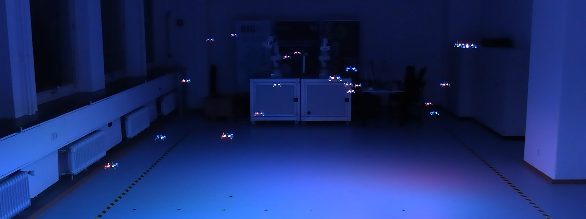
Many of you may be familiar with the “Decentralized Swarm Demo” we have been showcasing at fairs. Today, we’re excited to introduce its upgraded version, the “Decentralized Brushless Swarm Demo”, that utilizes our latest products! Get ready for an even more impressive experience that takes swarm autonomy to the next level!
This demo utilizes the Lighthouse Positioning System for onboard positioning and peer-to-peer communication between the drones for collision avoidance. The fully autonomous takeoff/landing is achieved with the new Crazyflie 2.1 Brushless charging dock, while the bright LEDs under each Crazyflie are prototypes for a new high-power LED deck that is cooking in the Bitcraze pots at the moment.
You can appreciate the stability in this short video:
The Crazyflie 2.1 Brushless Swarm is much more robust and stable than the normal Crazyflie Swarm, as the new powerful motors allow each drone to perform quick maneuvers to avoid its neighbors. We also observed a much longer flight time than we had with Crazyflie 2.1+ – a full swarm of 9 copters could stay up for around 9 minutes before running out of batteries.
Using our own products—especially those in early access—is a crucial part of development. It allows us to encounter real-world issues that our users might face. In this case, we discovered that Lighthouse decks could be damaged during charging if pins protrude from the bottom of the Brushless. This can cause wiring issues with the dock.
If you’re using these components, please ensure that no pins are sticking out beneath the Brushless, or cover the pins at the bottom. We used the battery holder deck to avoid further issues.
The release of the Crazyflie 2.1 Brushless charging dock makes it possible for everyone to recreate demos like this so make sure to check it out at our store. The source code of the demo can be found on github at the crazyflie-firmware-experimental repository under the arena-demo branch.
Simulators are one of the most important tools used in robotics research. They usually are designed for different purposes with different levels of complexity. For example, simulators with low computational overhead that are parallelizable are mainly used for either training reinforcement learning algorithms or Monte Carlo sampling for verification of task completion in a nondeterministic environment. Some simulators also use rendering engines for the graphical display of models and the environment or when cameras are intended to be used in the robotics platform. Simulation is also useful for the development and deployment of new robotics firmware features where the firmware is compiled on a test machine and run in the loop with a simulated sensor suite. This simulator configuration is known as software-in-the-loop (SITL) because the vehicle firmware is intended to be run in the loop with the simulated vehicle physics and/or rendering engine. This feature is supported by autopilot suites such as PX4, ArduPilot, CogniPilot, and BetaFlight. This feature is not officially supported yet for Crazyflies because it requires a large overhaul of the firmware to be able to compile on a desktop machine and interact with different simulators such as Gazebo, Webots, PyBullet, CoppeliaSim, Isaac Sim, or Unreal Engine.
CrazySim
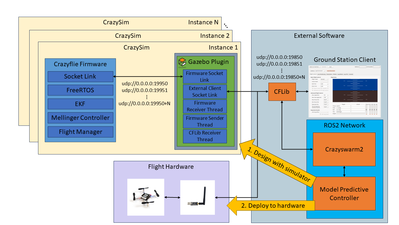
Last summer I began working with Crazyflies and noticed this Crazyflie simulator gap. I stumbled on a community-developed project for Crazyflie SITL called sim_cf. This project is exactly what I was looking for. However, the firmware used by the project is from July 2019 and the official firmware has had over 2000 commits made since then. The project also uses ROS 1, Gazebo Classic, and doesn’t support the Crazyflie Python library (CFLib). Using this project as a starting point I set out to develop CrazySim–a Crazyflie SITL project that doesn’t require ROS, uses Gazebo Sim, and supports connectivity through CFLib. Using CFLib we can connect the simulator to external software such as Crazyswarm2 or the Crazyflie ground station client. Users test their control algorithms in the external software using the simulator interface before deploying to real flight hardware.
An example of offboard model predictive control design and deployment workflow using CrazySim.
Using the Crazyflie Client for PID Tuning
We have also provided a modified Crazyflie client for CrazySim support. The Crazyflie client is a cool tool for testing a single drone in hardware. We can perform command based flight control, look at real time plots, save log data, and tune PID values in real time. The PID values are typically tuned for an out of the box Crazyflie. However, when we modify the Crazyflie and add extra weight through batteries, decks, and upgraded thrust motors then the behavior of the Crazyflie will change. If a user wants to tune a custom Crazyflie setup, then they can add additional models in this folder with their own motor and mass properties. Then they just need to add it to the list of supported models in either of the launch scripts. There is already an example model for the thrust upgrade bundle. Documentation for installing the custom client can be found here.
PID tuning a simulated Crazyflie using CrazySim on the Crazyflie PC client.
Crazyswarm2
We can now connect to the simulated Crazyflie firmware using CFLib. Therefore, we can set up a ROS 2 interface through Crazyswarm2 for swarm command and control through ROS 2 topics and services. To do this we first startup the drones using any of the launch scripts.
Then, we bring up Crazyswarm2 after setting up the configuration file for the number of drones chosen.
ros2 launch crazyflie launch.py backend:=cflib
We demonstrate an example of how we can control a swarm of drones using Crazyswarm2 GoTo service commands.
Crazyswarm2 GoTo service commands using CrazySim.
ICRA 2024
CrazySim is also being presented as a paper at the 2024 IEEE International Conference on Robotics and Automation in Yokohama, Japan. If you are attending this conference and are interested in this work, then I invite you to my presentation and let me know that you are coming from this blog post after. For the paper, I created a multi agent decentralized model predictive controller (MPC) case study on ROS 2 to demonstrate the CrazySim simulation to hardware deployment workflow. Simulating larger swarms with MPC may require a high performance computer. The simulations in this work were performed on an AMD Ryzen 9 5950X desktop processor.
Model predictive control case study for ICRA 2024 paper.
Today, Lennart Bult from Emergent Swarns presents us with this project of a 24/7 swarming demo. Enjoy!
Over the last few months our team has been working on creating a 24/7 swarming demo. Initially tasked by Guido de Croon and Chris Verhoeven from TU Delft MAVLab and the TU Delft Robotics Institute, we set out to find our way within the Crazyflie ecosystem to gradually increase the size and capabilities of the swarm. In this article we will first talk about some of the work and methods that we used. After that, we will introduce the TU Delft Science Centre Swarming Lab and talk about some applications of swarming drones.
Developing the 24/7 swarm
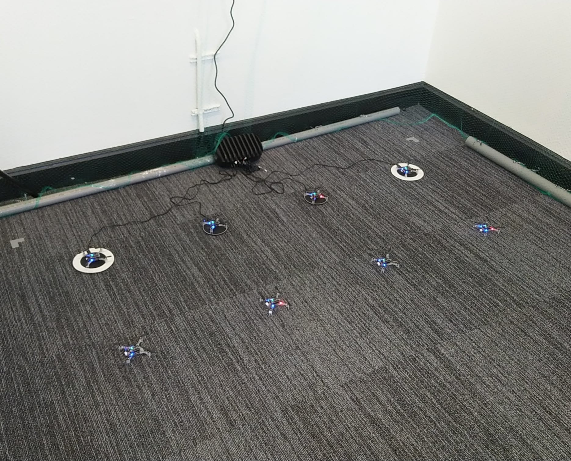
The project started in February with the goal of creating a physical swarm capable of real-time collision avoidance with drones and static obstacles. We started out with three drones equipped with the Flow Deck, and by setting them up in a clever way we could perform the first collision avoidance and landing tests. We were impressed with the performance we got out of the Flow Deck, however, eventually, it is mostly a battle against the drift of the position estimate, that is, we could increase some of the margins on the collision avoidance only so far before we would either fly out of the test zone or collide with another drone. Luckily with short test flights, we were able to see some of the flaws in our algorithms and correct them before testing with the new setup.
Setup after the first expansion to eight drones.
After a few weeks of testing we got approved for the first swarm expansion, five more drones and a Lighthouse positioning setup. This is when we could do our first real tests with the collision avoidance algorithm, which, much to our own surprise, worked on the first try. This is also when we first posted a project update on LinkedIn. There were however a lot of bugs that still needed to be worked out, and a lot of system experience still to be gained. After flying for a bit longer we noticed that some of the drones would flip quite often, which is when we discovered that we needed the thrust upgrade to control the additional weight of the larger battery and charging deck.
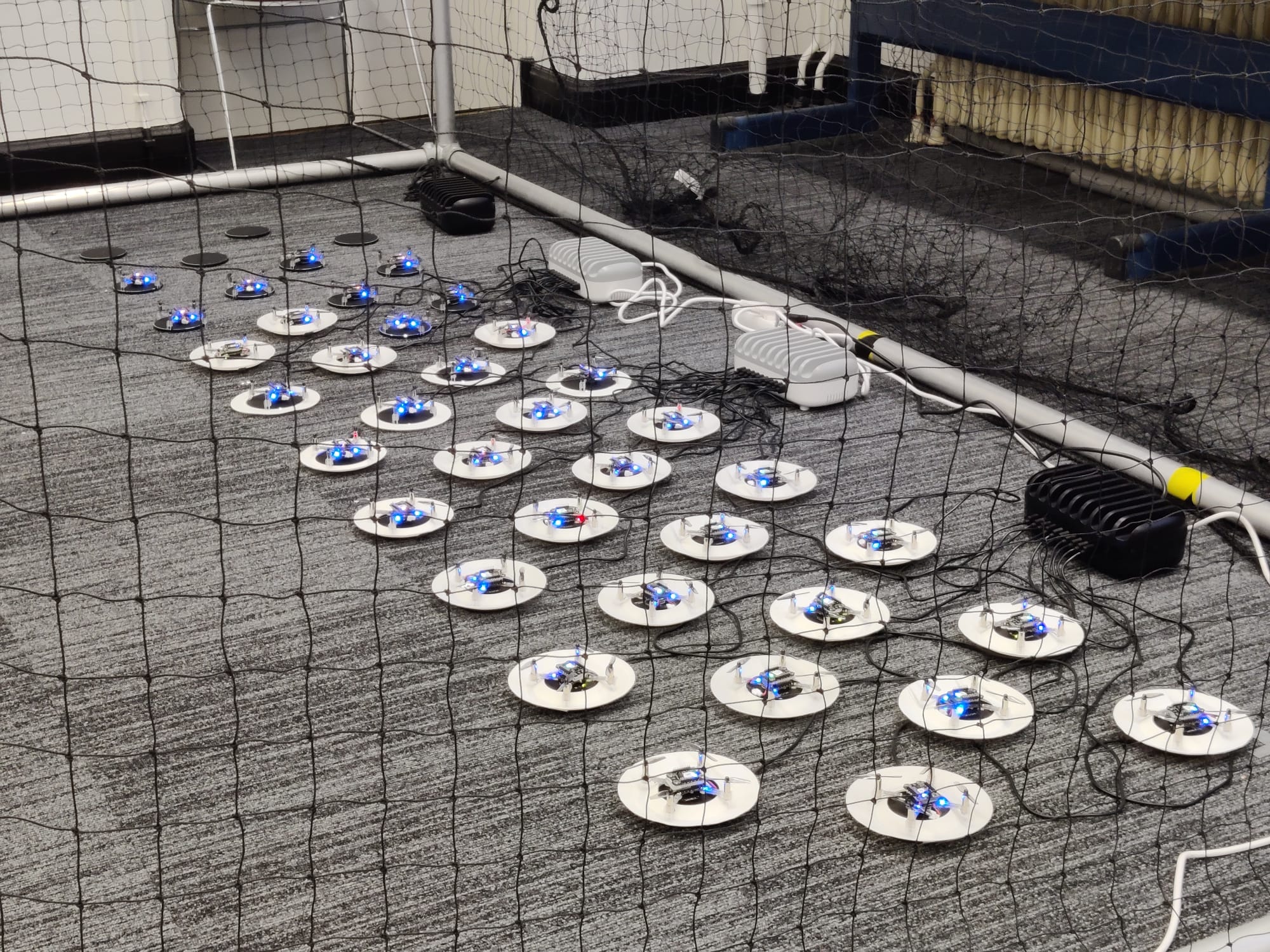
For the charging setup we took inspiration from the Bitcraze IROS 2022 demo; we 3D printed sloped landing pads that we tape onto a wireless charger. After a few iterations we landed on a design that uses minimal printer resources and allows the Crazyflie to land a bit off-center. This last feature turned out to be quite useful considering the large amount of destabilizing airflow that is generated by 40 drones. After receiving the last order of drones we also expanded the charging setup, which at this point takes up quite a bit of floor space. There are some ideas to create a vertical landing pad stack, which would bring the additional challenge of missing the landing pad not being an option.
All 40 drones recharging before their next flight.
After prototyping the charging setup and building confidence with the initial setup, we were confident enough in our system capabilities to expand it to the point where a continuous demo of 5-8 drones is possible. Although the system integration of the previous expansion went without much trouble, we did encounter a few issues when expanding to 40 drones. The first issue of which was radio communication, we noticed that a delay in the radio communication would be present if we increased the update rate above a certain level for a specific number of drones per radio. The second issue we encountered were performance drops related to the violation of certain bounds in the collision avoidance algorithm. These two issues were very difficult to debug since it was not immediately obvious where the source of the issue was.
The third and last major issue was the increase in destabilizing airflow of 40 drones compared to 8. With 40 drones there is a noticeable breeze when you stand next to the drone cage, which is nice for summertime, but not so nice when drones need to land in a tight-packed configuration. To combat this issue there is a limit to the amount of drones that can land at the same time. There is also a minimum separation distance between two active landing pads, which reduced the severity of the induced turbulence. There are still ongoing efforts to increase the landing success rate, which is currently affected by drones running out of power during the landing procedure.
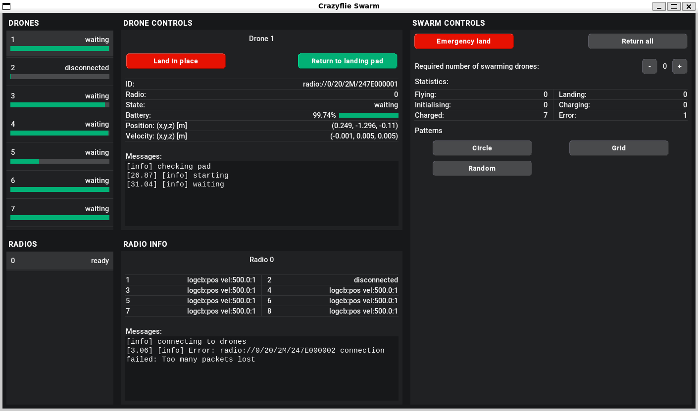
To control and monitor the swarm we designed a custom GUI, an impression of which you can see below. Although some of the buttons are still a work in progress, there are a lot of features that have already proven very useful, especially when testing a new feature.
V1 of the graphical user interface developed for the 24/7 swarm.
The code base that we created for the swarm will be largely open-sourced (only the collision avoidance will not be open-source) to provide researchers all around the world with the possibility to setup their own Crazyflie swarm for research. You can find the repository through this link. Note that the documentation and code base are still under development and might contain bugs/errors.
Human interaction
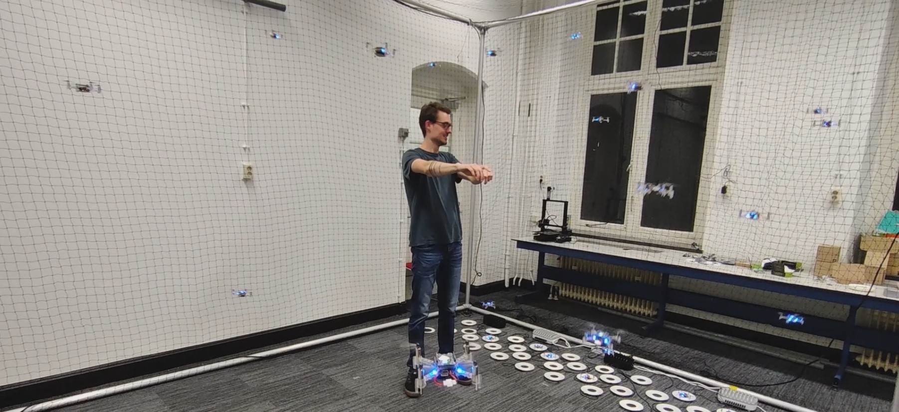
After creating all functionality to provide a continuously operating swarm demo, it was time to work on some of our stretch goals: 1. walking through the swarm whilst it is operating and 2. controlling the swarm using our arms. In the image below you can see an impression of precisely this functionality. The drones are following the operator’s gesture commands whilst performing live collision avoidance with an operator.
Team member Seppe directing the 40 drone swarm, see the full video here.
This demo requires multiple techniques and hardware elements working together to create a relatively low-latency, human-controlled swarm. We used a Kinect-like 3D sensor to perform human pose estimation, we subsequently used this data to create a dynamic obstacle in our collision avoidance software. An important element to consider here is the synchronization of the Lighthouse- and 3D sensor coordinate frames, i.e. without proper calibration the human will not be correctly positioned with respect to the drones and the drones will crash into the human. The interaction between the swarm control software and the human gesture commands also requires careful consideration, proper tuning is required to ensure a responsive system that is reliable and not too aggressive.
TUD Science Centre Swarming Lab
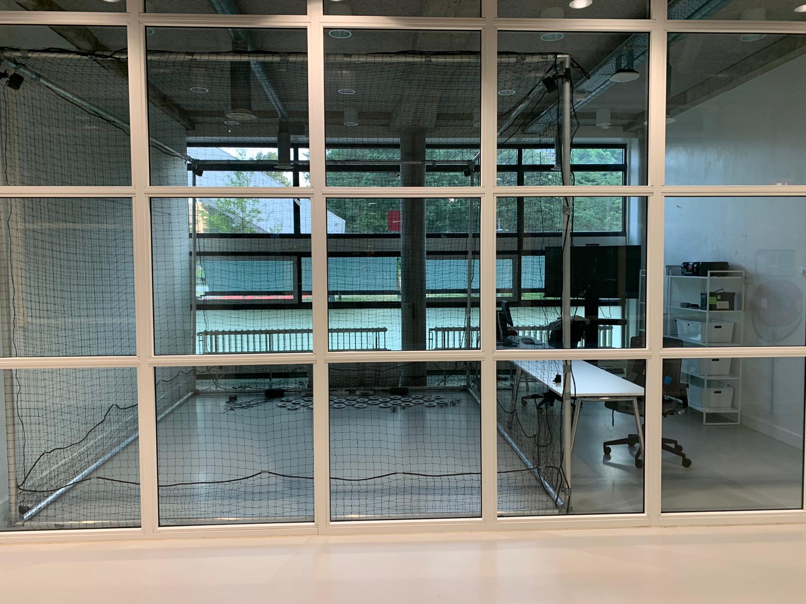
The next step in this project will be to set up the swarm at its new location, the TU Delft Science Centre. Here, the swarm will first and foremost be visible as a public demo, showcasing the capabilities of TU Delft state-of-the-art swarming research. There will also be a focus on developing the swarm as a research platform. This will allow TU Delft students and researchers to extend swarm functionalities and test their theory on a physical swarming system. Besides demos and academic research, there will also be worked on developing educational applications across the full educational board (primary school, high school and applied education). If you are interested in working on, or collaborating with the swarming lab on any of the above-mentioned tasks, feel free to email the lab management at operations.swarminglab@tudelft.nl.
The TU Delft Swarming Lab setup with 40 drones and charging pads for continuous operations and research.
Applications of Swarming
There are a lot of potential use-cases for fully autonomous drone swarms, ranging from indoor applications such as warehouse monitoring and factory inspection to outdoor applications such as search and rescue and surveillance. In our opinion, the true potential of drone swarms lies in applications where there is a significant need for a scalable system with a lot of built-in redundancy. A lot of additional use cases open up when we consider fully onboard autonomous systems, where the full benefits of decentralized swarming can be utilized. Currently, the size of drones needed to achieve such feats is quite large, though maybe in a few years, we could see more and more being done on drone platforms such as the Crazyflie.
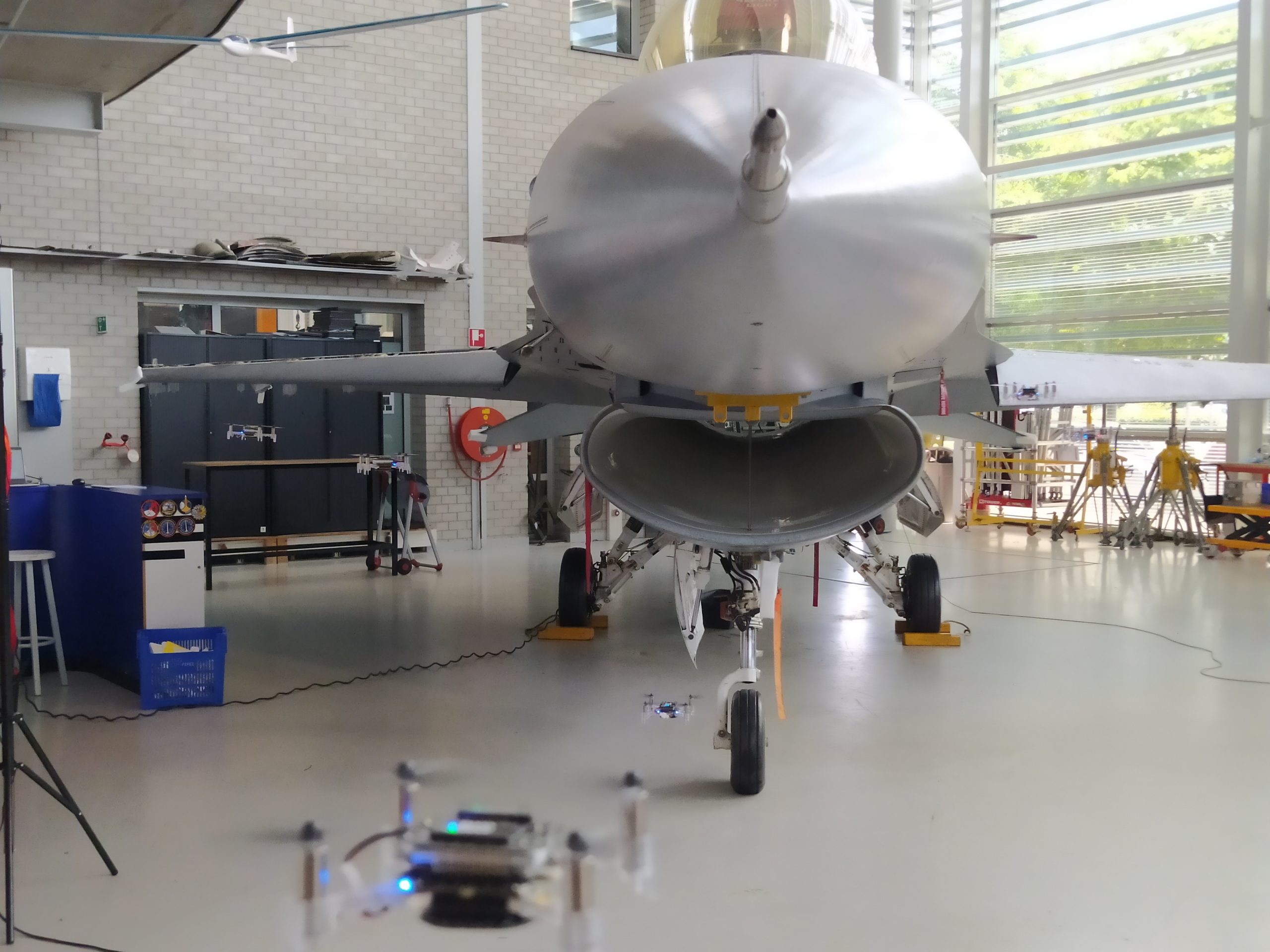
A swarm inspection of an F-16 Fighting Falcon at Deltion College in Zwolle, the Netherlands.
An interesting area of application for drone swarms could be in the inspection of aircraft. Drone swarms provide a scalable and flexible means to perform a fast inspection of aircraft across an entire airfield or military base. To showcase that this can be done with any size of drone, we went to Deltion College in Zwolle to perform a mock inspection of an F-16 fighter jet. Above you can see an impression of the inspection. Another area of application is search and rescue, where there is a need for systems that can find people or objects of interest in unknown and cluttered environments. Furthermore, the area that needs to be searched is usually very large and sometimes difficult to travel on foot. A drone swarm could provide fast and reliable coverage of the area of interest, whilst providing full data traceability. Seppe and Lennart will work on creating drone swarms for these use cases with the start-up Emergent Swarms.