Today, our guest Airi Lampinen from Stockholm University is presenting the second Drone Arena Challenge. Enjoy!
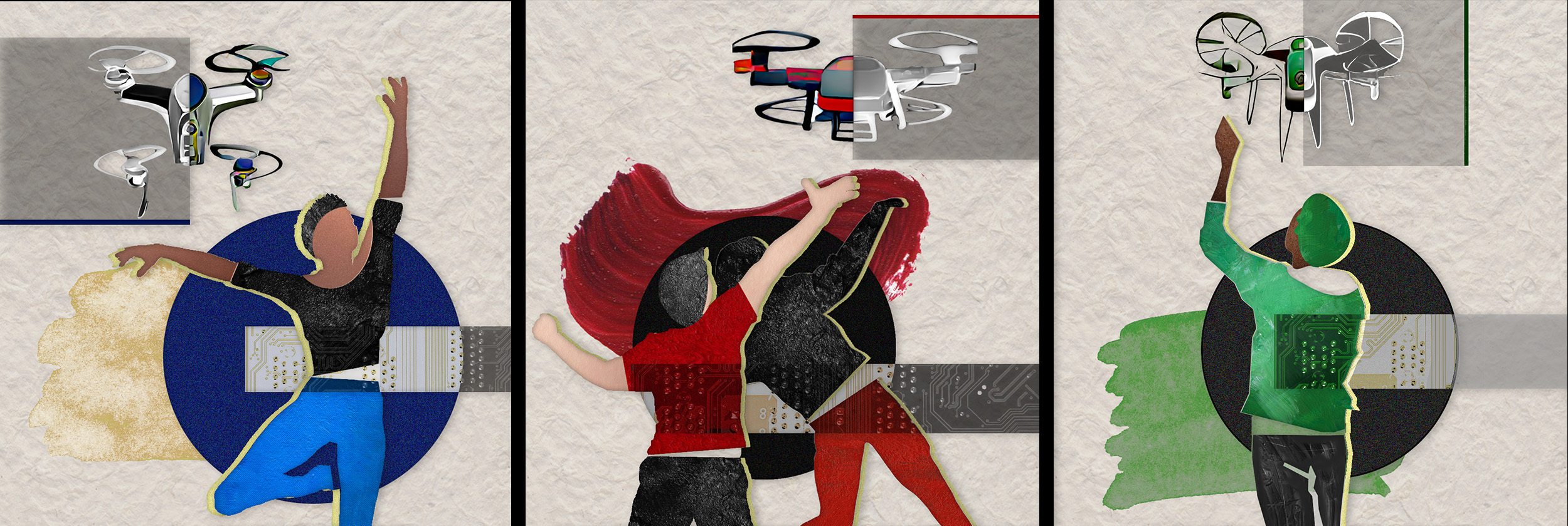
Welcome to the second Drone Arena Challenge, a one-of-a-kind interactive experience with Bitcraze’s Crazyflie! This year, the challenge is focused on moving together with drones in beautiful, curious, and provocative ways – without needing to write a single line of code!
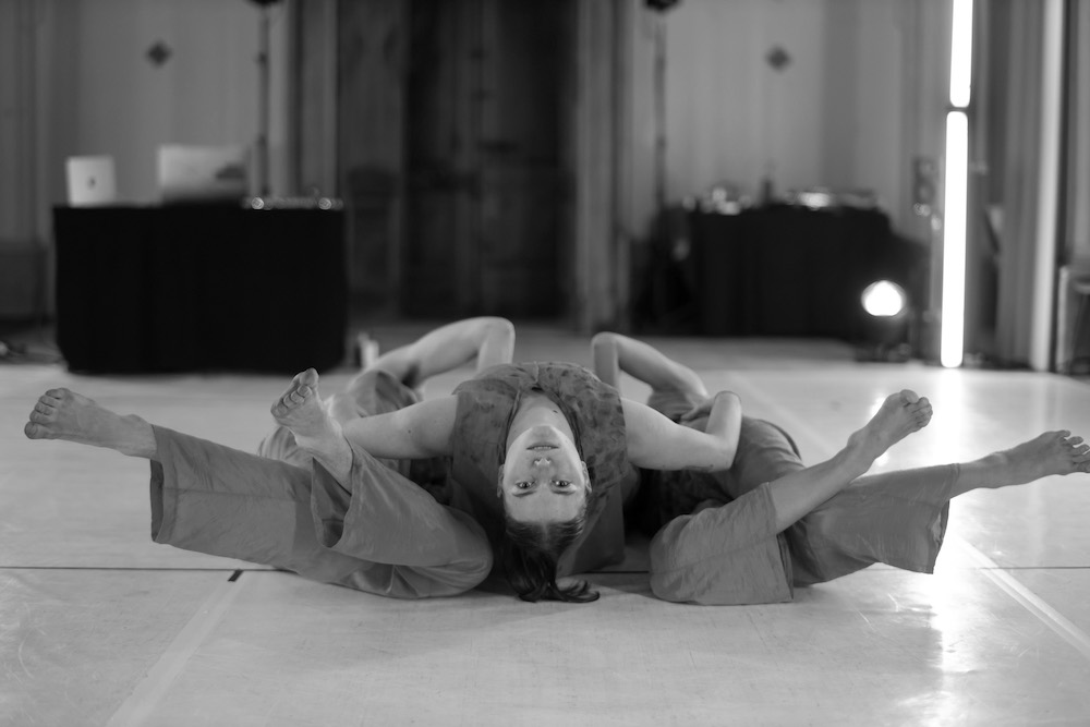
Moving with drones. Image credit: Rachael Garrett.
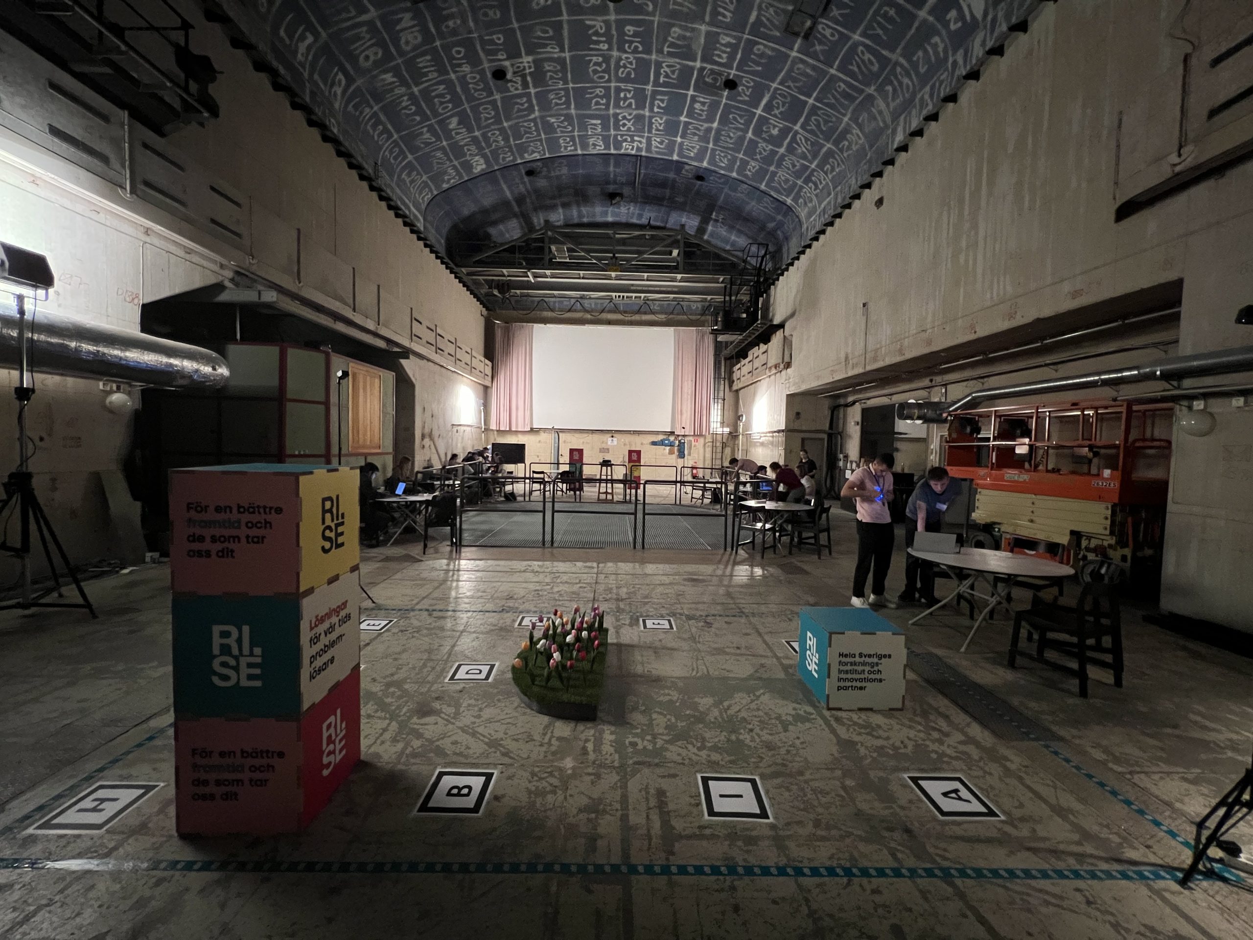
What, when, where? The event takes place May 16-17, 2023 at KTH’s Reactor Hall in Stockholm – a dismantled nuclear reactor hall – which provides a unique setting for creative human–drone encounters. You don’t need your own drone or be able to program a drone to participate! We will provide the drone equipment (a Crazyflie 2.1 equipped with the AI-deck) and take care of everything necessary to make them fly. What you need to do is to be creative and move together with the drones to set up the best show you can deliver! There’ll be a jury judging the final performances and we have exciting prizes for the most successful teams!
Drone Arena in the Reactor Hall. Picture from the first challenge, held in June 2022. Picture credit: Fatemeh Bakhshoudeh
Who can join? Anyone irrespective of training, profession, and past experience with drones or performing arts is welcome to participate. Participants need to be at least 18 years old. If you are curious about how technology and humans may play together, enthusiastic about the Crazyflie, or eager to learn how to move with the Crazyflie, this event is for you. We welcome up to 10 pairs (teams of 2 people) to participate in the challenge.
Registration is already open, with only a few spots remaining. We encourage those interested to sign up as soon as possible to secure their spot!
Program & prizes? On the first day of the hackathon, we will host a keynote speaker and a short information session to explain what participants are expected to do and what support is available for them. The teams will then have access to the Reactor Hall to work on the challenge and explore moving with their drone – we offer long hours but each team is free to choose how much they want to work. (The goal here is to have a good time!) The competition itself takes place on the second day. We’ve got exciting prizes for the most successful teams!
This week’s guest blogpost is from Matěj Karásek from Flapper Drones, about flying the Nimble + with a positioning system. Enjoy!
Flapper Drones are bioinspired robots flying by flapping their wings, similar to insects and hummingbirds. If you haven’t heard of Flappers yet, you can read more about their origins at TU Delft and about how they function in an earlier post and on our company website.
In this blogpost, I will write about how to fly the Flappers (namely the Flapper Nimble+) autonomously within a positioning system such as the Lighthouse, and will of course include some nice videos as well.
The Flapper Nimble+ is the first hover-capable flapping-wing drone on the market. It is a development platform powered by the Crazyflie Bolt and so it can enjoy most of the perks of the Crazyflie ecosystem, including the positioning systems as well as other sensors (check this overview). If you would like to get a Flapper yourself, just head to the Bitcraze webstore, where there are some units ready to be shipped! (At the time of writing at least…)
Minimal setup
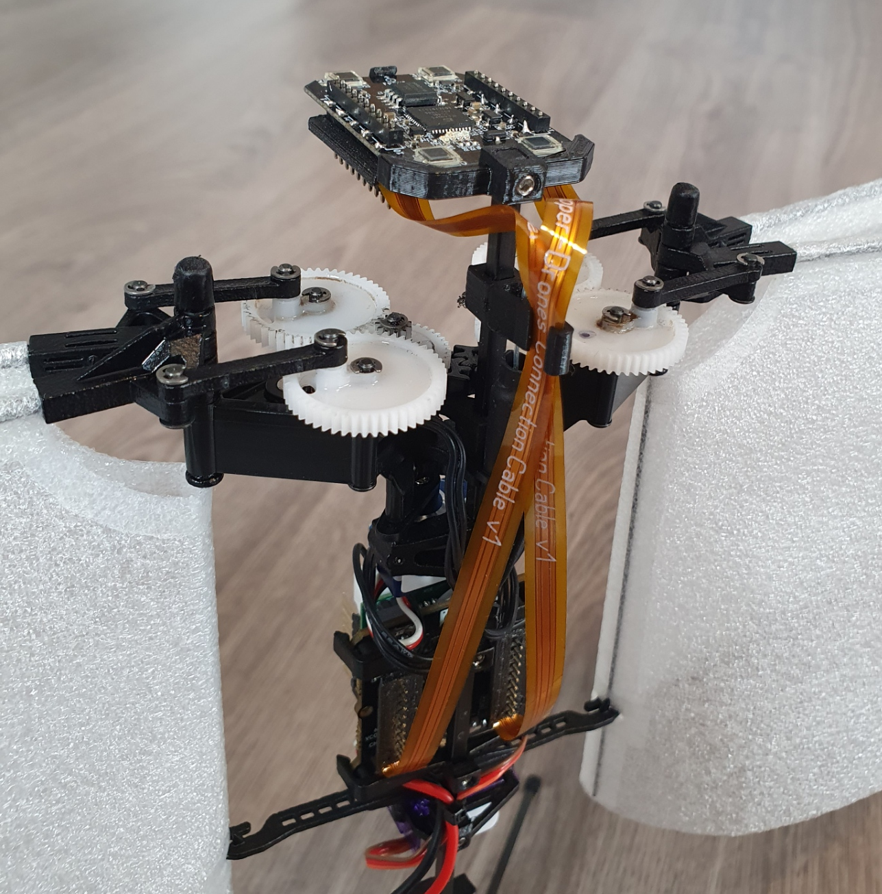
The minimal setup for flying in a positioning system is nearly identical as with a standard Crazyflie. Next to a Flapper with a recent firmware, a Crazyradio dongle, a positioning system (in this post we will use the Lighthouse), and a compatible positioning deck (Lighthouse deck) you will also need: 1) a mount, such that the deck can be attached on top of the Flapper, and 2) a set of extension cables. You can 3D print the mounts yourself (models here), the extension cable prototypes can either be inquired from Flapper Drones, or can be soldered by yourself (in that case, the battery holder deck, standard Crazyflie pin headers and some wires come handy). Just pay attention to connect the cables in the correct way, as if the deck was mounted right on top of the Bolt. The complete setup with the Lighthouse deck will look like this:
Lighthouse deck installation on a Flapper Nimble+. Make sure the extension cables are well secured (e.g. by using the additional cable mount) such they don’t get caught by the gears.
For the Lighthouse, as with regular Crazyflies, the minimum number of base stations (with some redundancy) is 2, but you will get larger tracking volume with more base stations. 4 base stations mounted at 3 m height will give you about 5 meters time 5 meters coverage, which is recommended especially if you want to fly more than 1 Flapper at a time (they are a bit larger than the Crazyflies, after all…). From now on, it is exactly the same as with standard Crazyflies. After you calibrate the Lighthouse system using the standard wizard procedure via the Cfclient, you can just go to the Flight Control Tab and use the “Command Based Flight Control” buttons to take-off, command steps in xyz directions and land. It is this easy!
Flapper Nimble+ in Lighthouse flown via Command Based Flight Control of cfclient
Assisted flight demo
We used this setup in February for the demos we were giving at the Highlight Delft festival in the Netherlands. This allowed people with no drone piloting skills (from 3-year-olds, to grandmas – true story) fly and control the Flapper in a safe way (safe for the Flapper, as the Flapper itself is a very safe platform thanks to its soft wings and low weight). To make it more fun, and even safer for the Flapper, we used a gamepad instead of on screen buttons, and we modified the cfclient slightly such that the flight space can be geofenced to stay within the tracking volume.
Flight demo at Highlight Delft festival, using the Lighthouse and position hold assistance
If you would like to try it yourself (it works also with standard crazyflies), the source code is here (just keep in mind it is experimental and has some known bugs…). To fly in the position-assisted mode, you need to press (and keep pressing) the Alt 1 button, and use the joysticks to move around (velocity commands, headless mode). Releasing the Alt 1 button will make the Flapper autoland. Autoland will also get triggered when the battery is low. You can still fly the Flapper in a direct way when pressing Alt 2 instead.
Flying more Flappers at a time
Again, this is something that works pretty much out of the box. As with a regular crazyflie, you just need to assign a unique address to each of the Flappers and then use e.g. this example python script to run a preprogrammed sequence.
With a few extra lines of code, we pulled this quick demo at the end of the Highlight Delft festival, when we had 30 minutes left before packing everything (one of the Flappers decided to drop its landing gear, probably too tired after 3 evenings of almost continuous flying…):
Sequence with 3 Flappers within Lighthouse positioning system
Other positioning systems
Using other positioning systems is equally easy. In fact, for the Loco Positioning system, the deck can even be installed directly on the Flapper’s Bolt board (no extension cables or mounts are needed). As for optical motion tracking, we do not have experience with Qualisys and the active marker deck, but flying with retro-reflective markers within OptiTrack system can be setup easily with just a few hacks.
When choosing and setting up the positioning system, just keep in mind that due to its wings, the Flapper needs to tilt much more to fly forward or sideways, compared to a quadcopter. This is not an issue with the Loco Positioning system (but there can be challenges with position estimation, as described further), but it can be a limitation for systems requiring direct line of sight, such as the Lighthouse or optical motion tracking.
Ongoing work
In terms of control and flight dynamics, the Flapper is very different from the Crazyflie. Thus, for autonomous flight, there remains room for improvement on the firmware side. We managed to include the “flapper” platform into the standard Crazyflie firmware (in master branch since November 2022, and in all releases since then), such that RC flying and other basic functionality works out of the box. However, as many things in the firmware were originally written only for a (specific) quadcopter platform, the Crazyflie 2.x, further contributions are needed to unlock the full potential of the Flapper.
With the introduction of “platforms” last year, many things can be defined per platform (e.g. the PID controller gains, sensor alignment, filter settings, etc.), but e.g. the Extended Kalman filter, and specifically the motion model inside, has been derived and tuned for the Crazyflie 2.x, and is thus no representative of the Flapper with very different flight dynamics. This is what directly affects (and currently limits) the autonomous flight within positioning systems – it works well enough at hover and slow flight, but the agility and speed achievable in RC flight cannot be reached yet. We are planning to improve this in the future (hopefully with the help of the community). The recently introduced out of tree controllers and estimators might be the way to go… To be continued :)
Thanks Matej ! And for those of you at home, don’t forget that we have our dev meeting next Wednesday (the 5th), where we’ll discuss about the Loco positioning system, but also will take some time for general discussions. We hope to see you there!
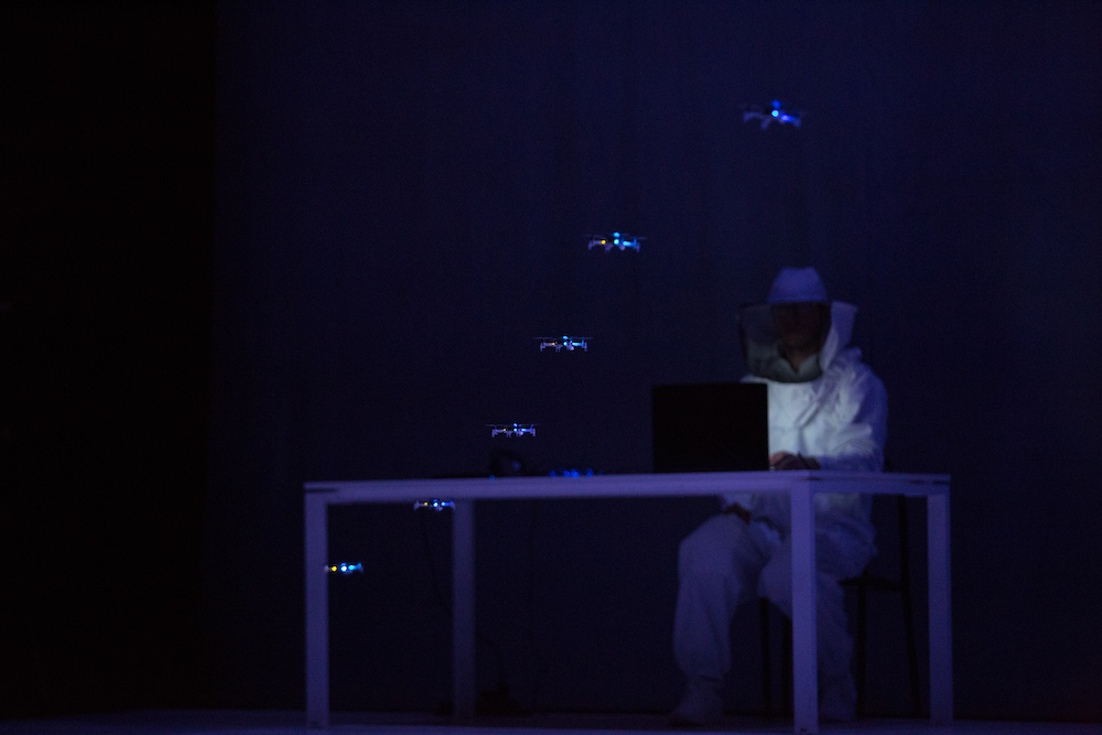
This week’s guest blogpost is from Florian Goralsky from Bok o Bok about their dance piece with multiple Crazyflies. Enjoy!
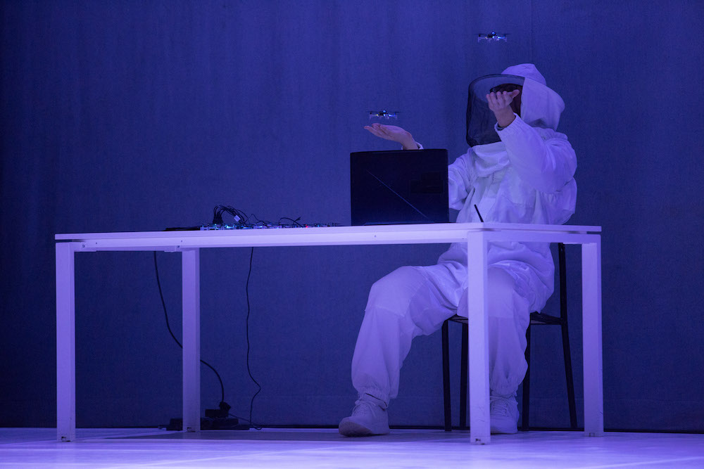
Flying bodies across the fields is a contemporary dance piece for four performers and a swarm of drones, exploring the phenomenon of the disappearance of bees and the use of pollinating drones to compensate for this loss. The piece attempts to answer this crucial question in a poetical way: can the machine create life and save us from ecological disaster?
We’re super excited to talk about a performance that we’ve been working on for the past two years in collaboration with Bitcraze. It premiered at the Environmental Forum, Centre Pompidou Paris, in 2021, and we’ve had the opportunity to showcase it at different venues since then. We are happy to share our thoughts about it!
Choreographic research
Beyond symbolizing current attempts to use drones to pollinate fields, the presence of the Crazyflie drones, supports the back and forth between nature and technology. We integrate a swarm, performing complex choreographies, which refer to the functioning of a beehive, including the famous “bee dance”, discovered by Karl von Frisch, which is used to transmit information on the food sources. Far from having a spectacular performance as its only goal, the synchronization of autonomous drones highlights bio-inspired computer techniques, focused on collective intelligence.
Making a dance performance with drones needs a high accuracy and adaptability, both before and during the show. Usually, we only have a few hours, sometimes even a few minutes, to setup the system according to the space. We quickly realized we needed pre-recorded choreographies, and hybrid choreographies where the pilot could have a few degrees of freedom on pre-defined behaviors.
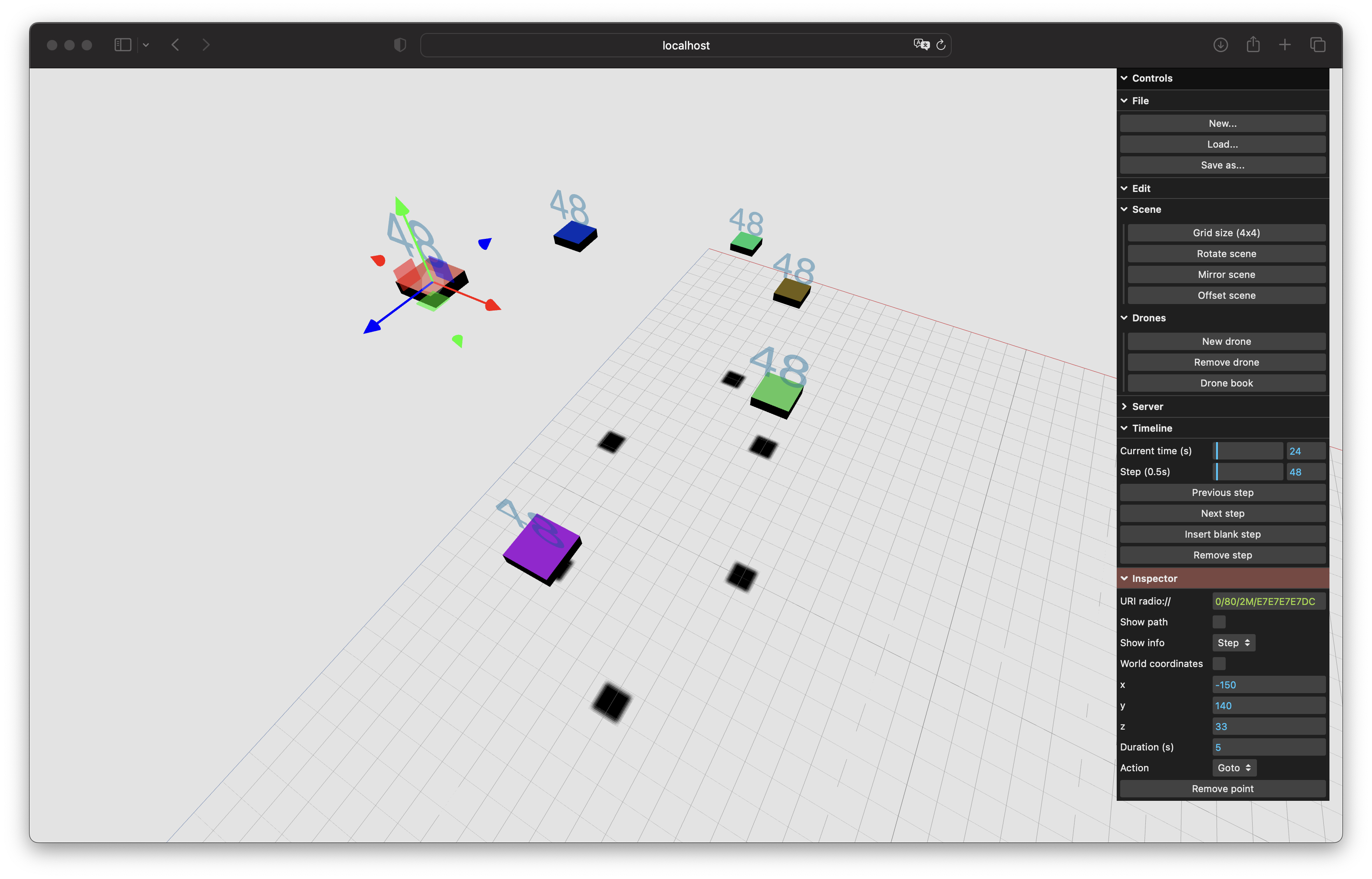
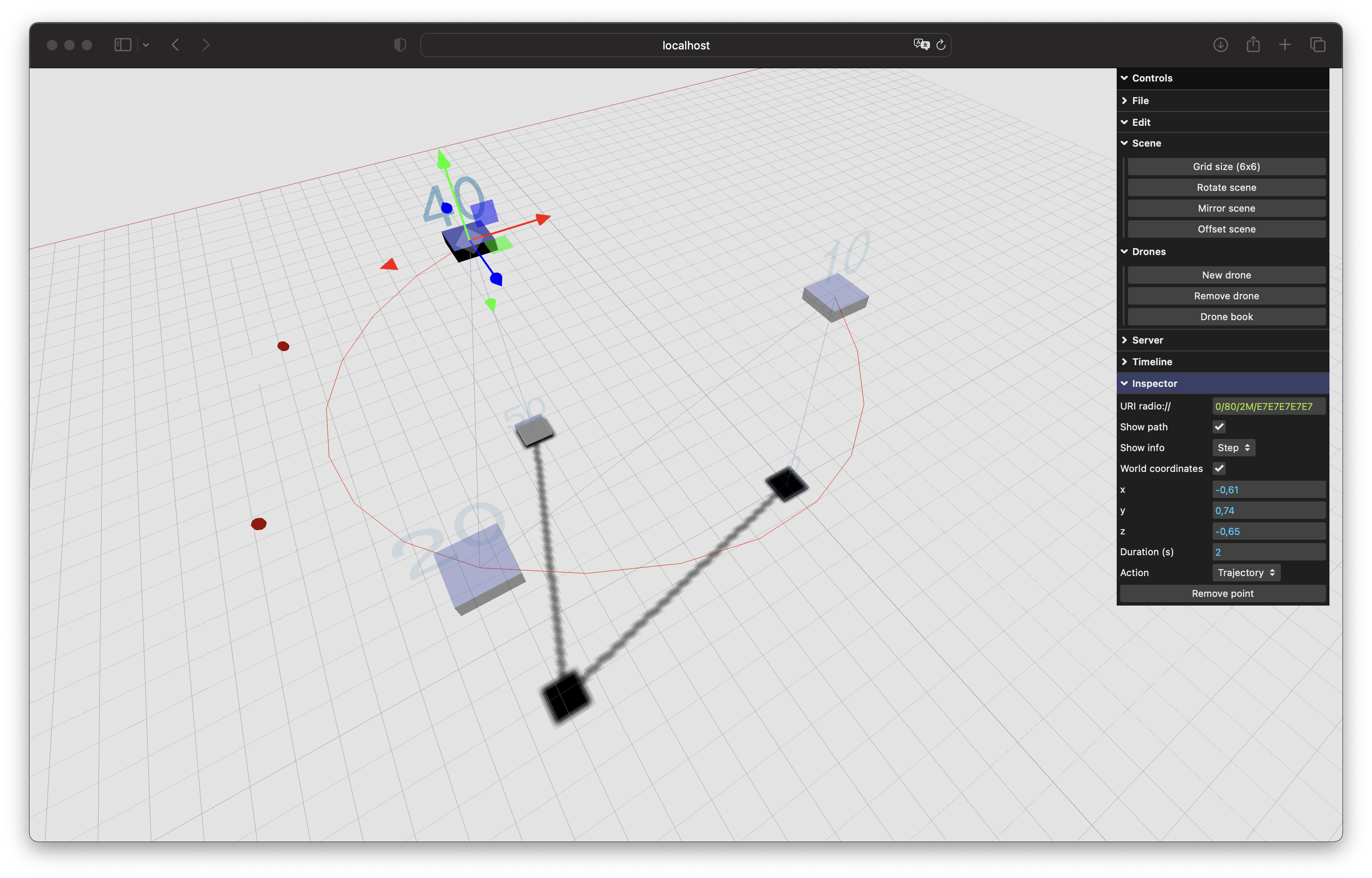
GUI Editor + Python Server
Taking this into account, we developed a web GUI editor, that is able to send choreographies created with any device to a Websocket Python server. The system supports any absolute positioning system (We use the Lighthouse), and then converts all the setpoints and actions to the Crazyflie API HighLevelCommander class. This system allows us to create, update, and test complex choreographies in a few minutes on various devices.
Preview position of six drones at a certain time.Early support of the CompressedTrajectories format, with Cubic bezier curves.
What is next?
We are looking forward to developing more dancers-drones interactions in the future. It will imply, in addition to the Lighthouse system, other sensors, in order to open up new possibilities: realtime path-finding, obstacle avoidance even during a recorded choreography (to allow improvisation), etc.
Bats navigate using sound. As a matter of fact, the ears of a bat are so much better developed than their eyes that bats cope better with being blindfolded than they cope with their ears being covered. It was precisely this experiment that helped the discovery of echolocation, which is the principle bats use to navigate [1]. Broadly speaking, in echolocation, bats emit ultrasonic chirps and listen for their echos to perceive their surroundings. Since its discovery in the 18th century, astonishing facts about this navigation system have been revealed — for instance, bats vary chirps depending on the task at hand: a chirp that’s good for locating prey might not be good for detecting obstacles and vice versa [2]. Depending on the characteristics of their reflected echos, bats can even classify certain objects — this ability helps them find, for instance, water sources [3]. Wouldn’t it be amazing to harvest these findings in building novel navigation systems for autonomous agents such as drones or cars?
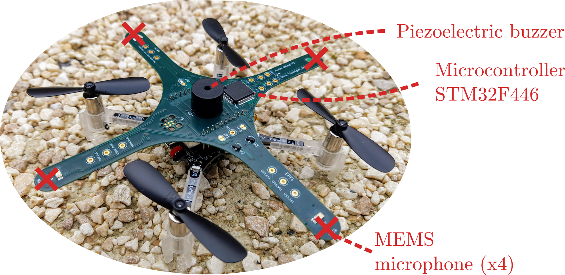
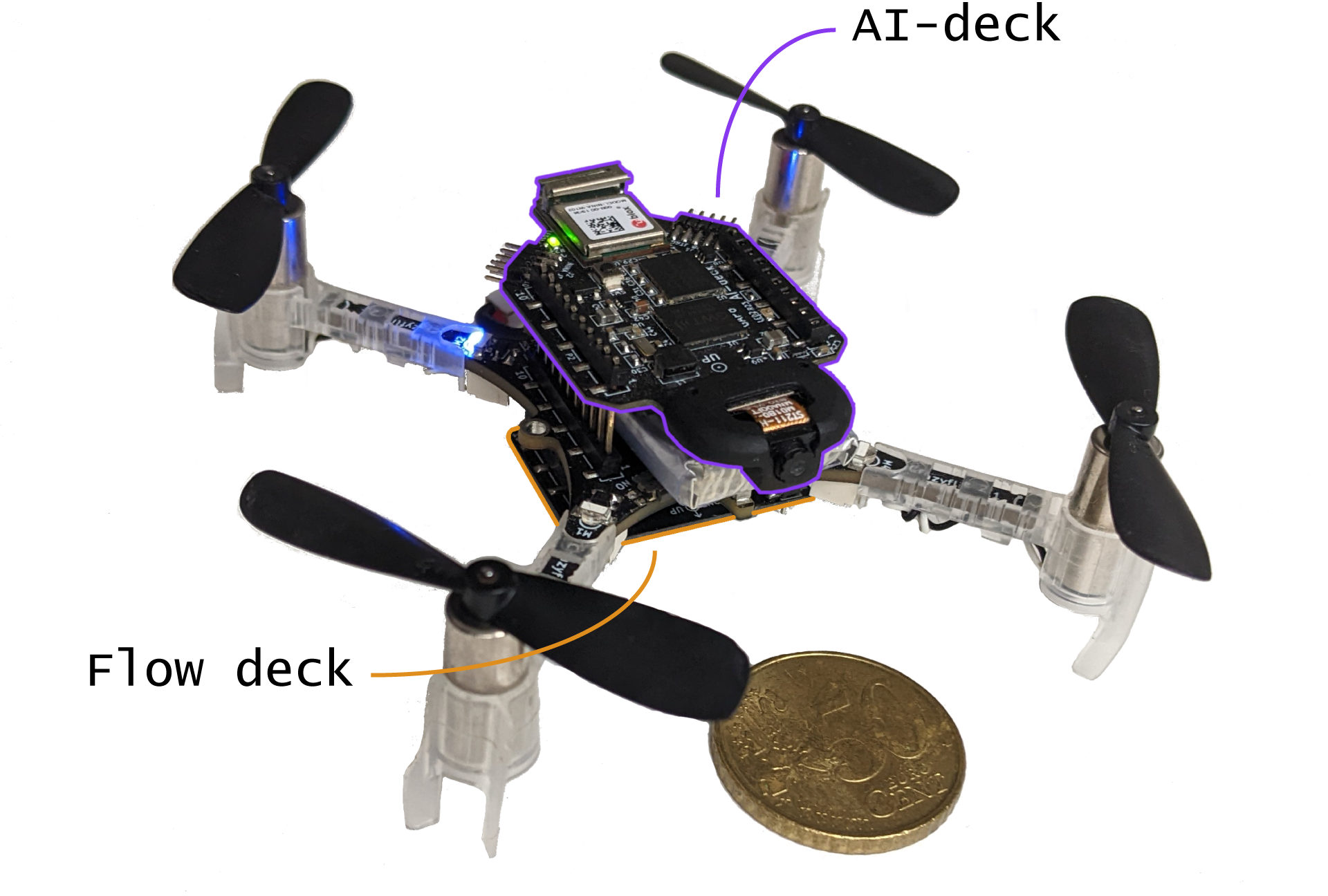
Figure 1: Meet “Crazybat”: the Crazyflie equipped with our custom audio deck including 4 microphones, a buzzer, and a microcontroller. Together, they can be used for bat-like echolocation. The design files and firmware of the audio extension deck are openly available, as is a ROS2-based software stack for audio-based navigation. We hope that fellow researchers can use this as a starting point for further pushing the limits of audio-based navigation in robotics. More details can be found in [4].
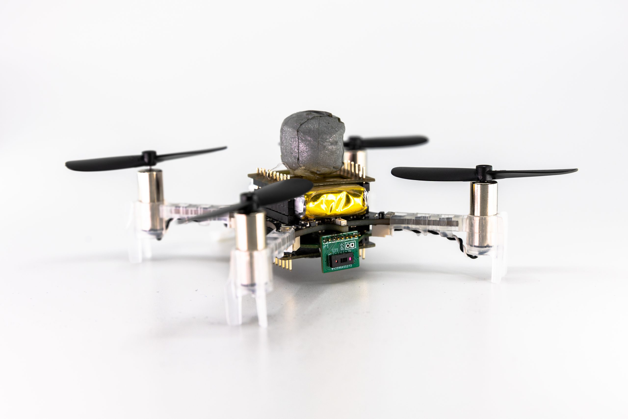
The quest for the answer to this question led us — a group of researchers from the École Polytechnique Fédérale de Lausanne (EPFL) — to design the first audio extension deck for the Crazyflie drone, effectively turning it into a “Crazybat” (Figure 1). The Crazybat has four microphones, a simple piezo buzzer, and an additional microprocessor used to extract relevant information from audio data, to be sent to the main processor. All of these additional capabilities are provided by the audio extension deck, for which both the firmware and hardware design files are openly available.1
Video 1: Proof of concept of distance/angle estimation in a semi-static setup. The drone is moved using a stepper motor. More details can be found in [4].
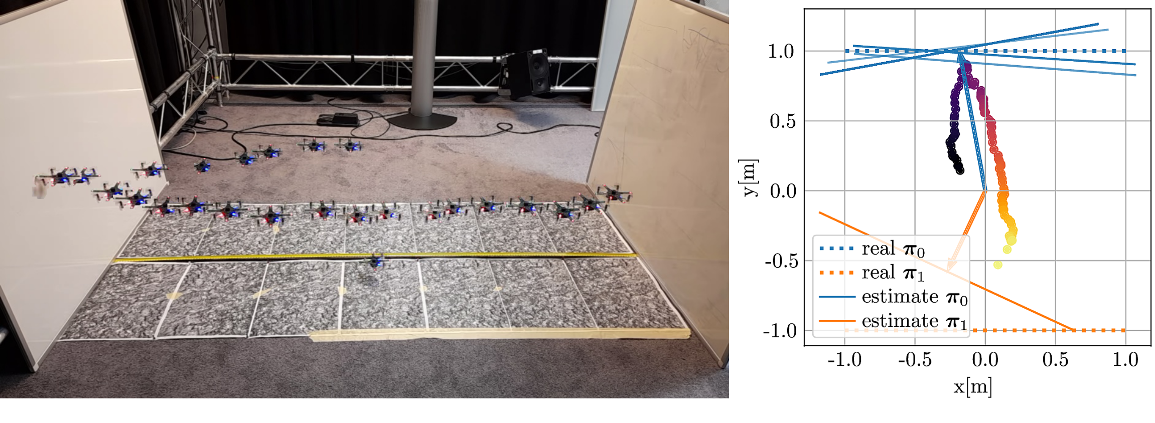
In our paper on the system [4], we show how to use chirps to detect nearby obstacles such as glass walls. Difficult to detect using a laser or cameras, glass walls are excellent sound reflectors and thus a good candidate for audio-based navigation. We show in a first semi-static feasibility study that we can locate the glass wall with centimeter accuracy, even in the presence of loud propeller noise (Video 1). When moving to a flying drone and different kinds of reflectors, the problem becomes significantly more challenging: motion jitter, varying propeller noise and tight real-time constraints make the problem much harder to solve. Nevertheless, first experiments suggest that sound-based wall detection and avoidance is possible (Figure and Video 2).
Video 2: The “Crazybat” drone actively avoiding obstacles based on sound. Figure 2: Qualitative results of sound-based wall localization on the flying “Crazybat” drone. More details can be found in [4].
The principle we use to make this work is sound-based interference. The sound will “bounce off” the wall, and the reflected and direct sound will interfere either constructively or destructively, depending on the frequency and distance to the wall. Using this same principle for the four microphones, both the angle and the distance of the closest wall can be estimated. This is however not the only way to navigate using sound; in fact, our software stack, available as an open-source package for ROS2, also allows the Crazybat to extract the phase differences of incoming sound at the four microphones, which can be used to determine the location of an external sound source. We believe that a truly intelligent Crazybat would be able to switch between different operating modes depending on the conditions, just like bats that change their chirps depending on the task at hand.
Note that the ROS2 software stack is not limited to the Crazybat only — we have isolated the hardware-dependent components so that the audio-based navigation algorithms can be ported to any platform. As an example, we include results on the small wheeled e-puck2 robot in [4], which shows better performance than the Crazybat thanks to the absence of propeller noise and motion jitter.
This research project has taught us many things, above all an even greater admiration for the abilities of bats! Dealing with sound is pretty hard and very different from other prevalent sensing modalities such as cameras or lasers. Nevertheless, we believe it is an interesting alternative for scenarios with poor eyesight, limited computing power or memory. We hope that other researchers will join us in the quest of exploiting audio for navigation, and we hope that the tools that we make publicly available — both the hardware and software stack — lower the entry barrier for new researchers.
1 The audio extension deck works in a “plug-and-play” fashion like all other extension decks of the Crazyflie. It has been tested in combination with the flow deck, for stable flight in the absence of a more advanced localization system. The deck performs frequency analysis on incoming raw audio data from the 4 microphones, and sends the relevant information over to the Crazyflie drone where it is converted to the CRTP protocol on a custom driver and sent to the base station for further processing in the ROS2 stack.
References
[1] Galambos, Robert. “The Avoidance of Obstacles by Flying Bats: Spallanzani’s Ideas (1794) and Later Theories.” Isis 34, no. 2 (1942): 132–40. https://doi.org/10.1086/347764.
[2] Fenton, M. Brock, Alan D. Grinnell, Arthur N. Popper, and Richard R. Fay, eds. “Bat Bioacoustics.” In Springer Handbook of Auditory Research, 1992.https://doi.org/10.1007/978-1-4939-3527-7.
[3] Greif, Stefan, and Björn M Siemers. “Innate Recognition of Water Bodies in Echolocating Bats.” Nature Communications 1, no. 106 (2010): 1–6. https://doi.org/10.1038/ncomms1110.
[4] F. Dümbgen, A. Hoffet, M. Kolundžija, A. Scholefield and M. Vetterli, “Blind as a Bat: Audible Echolocation on Small Robots,” in IEEE Robotics and Automation Letters (Early Access), 2022. https://doi.org/10.1109/LRA.2022.3194669.
Tiny quadcopters like the Crazyflie can be operated in narrow, cluttered environments and in proximity to humans, making them the perfect candidate for search-and-rescue operations, monitoring of crop in a greenhouse, or performing inspections where other flying robots cannot reach. All these applications benefit from autonomy, allowing deployment without proximity to a base station or human operator and permitting swarming behavior.
Achieving autonomous navigation on nano quadcopters is challenging given the highly constrained payload and computational power of the platform. Most attention has been given to monocular solutions; the camera is a lightweight and energy-efficient passive sensor that captures rich information of the environment. One of the most important monocular visual cues is optical flow, which has been exploited on MAVs with higher payload for obstacle avoidance [1], depth estimation [2] and several bio-inspired methods for autonomous navigation [3–7].
Optical flow describes the apparent visual variations caused by relative motion between an observer and their surroundings. This rich visual cue contains tangled information of velocity and depth. However, calculating optical flow is expensive. The field of optical flow estimation is and has been for a couple of years dominated by convolutional neutral networks (CNNs). Despite efforts to find architectures of reduced size and latency [8-10], these methods are still highly computationally expensive, running at several to tens of FPS on modern desktop GPUs and requiring millions of parameters to run, rendering them incompatible with edge hardware.
To this end, we present “NanoFlowNet: Real-Time Dense Optical Flow on a Nano Quadcopter”, submitted to an international robotics conference, which introduces NanoFlowNet, a CNN architecture designed for real-time, fully on-board, dense optical flow estimation on the AI-deck.
CNN architecture
We adopt semantic segmentation CNN STDC-Seg [11] and modify it for optical flow estimation. The resulting CNN architecture may be considered “real-time” on desktop hardware, for deployment on edge devices such as a nano quadcopter the net must be significantly shrunk. We improve the latency of the architecture in three ways.
First, we redesign the key convolutional modules of the architecture, the Short-Term Dense Concatenate (STDC) module. By reordering the operations within the strided variant of the module, we save, depending on the location of the module within the architecture, from over 10% to over 50% of the MAC operations per module, while increasing the number of output filters with large receptive field size. A large receptive field size is desirable for optical flow estimation.
Second, inspired by MobileNets [12], we globally replace ‘regular’ convolutions with depthwise separable convolutions. Depthwise separable convolutions factorize a convolution into a depthwise and pointwise convolution, effectively reducing the calculational expense at a cost in representational capacity.
Third, we reduce the input dimensionality. We train and infer network on grayscale input images, reducing the required on-board memory for storing images by a factor 2/3. Any memory saved on the AI-deck’s L2 memory can be handed to AutoTiler for storing the CNN architecture, speeding up the on-board execution. Requiring more of a speed-up, we run the CNN on-board at a reduced input resolution of 160×112 pixels. Besides the speed-up through saved L2, reducing the input resolution makes all operations throughout the network cheaper. We downscale training data to closely match the target resolution. Both these changes come at a loss of input information. We will miss out on small objects and small displacements that are not captured by the resolution.
To give some intuition of the available memory: Estimating optical flow requires two input images. Storing two color input images at full resolution requires (2 x 324x324x3=) 630 kB. The AI-deck has 512 kB of L2 memory available.
Motion boundary detail guidance
Inspired by STDC-Seg, we guide the training of optical flow with a train-time-only auxiliary task to promote the encoding of spatial information in the early layers. Specifically, we introduce a motion boundary prediction task to the net. The motion boundary ground truth can be found in the optical flow datasets. This improves performance by 0.5 EPE on the MPI Sintel clean (train) benchmark, at zero cost to inference latency.
Performance on MPI Sintel
Given the scaling and conversion to grayscale of input data, our network is not directly comparable with results reported by other works. For comparison, we retrain one of the fastest networks in literature, Flownet2-s [13], on the same data. Given the reduction in resolution, we drop the deepest two layers to maintain a reasonable feature size. We name the model Flownet2-xs.
We benchmark the performance of the architecture on the optical flow dataset MPI Sintel. NanoFlowNet performs better than FlowNet2-xs, despite using less than 10% of the parameters. NanoFlowNet achieves 5.57 FPS on the AI-deck. FlowNet2-xs does not fit on the AI-deck due to the network size. To put the achieved latency of NanoFlowNet in perspective, we execute FlowNet2-xs’ first two convolutions and the final prediction layer on the GAP8. The three-layer architecture achieves 4.96 FPS, which is slower than running the entire NanoFlowNet. On a laptop GPU, the two architectures accomplish similar latency.
Method
MPI Sintel (train) [EPE]
Frame rate [FPS]
Parameters
Clean
Final
GPU
GAP8
FlowNet2-xs
9.054
9.458
150
–
1,978,250
NanoFlowNet
7.122
7.979
141
5.57
170,881
Performance on MPI Sintel (train subset). (Average) end-to-end Point Error (EPE) describes how far off the estimated flow vectors are on average, lower is better.
Input frame IGround truth optical flowNanoFlowNet (ours)FlowNet2-xsInput frame IGround truth optical flowNanoFlowNet (ours)FlowNet2-xsQualitative comparison of optical flow estimates by NanoFlowNet(-s) and FlowNet2-xs on MPI Sintel (train) clean pass. NanoFlowNet and NanoFlowNet-s pick up on smaller moving objects, such as the person in the bottom row.
Obstacle avoidance implementation
We demonstrate the effectiveness of NanoFlowNet by implementing it in a simple, proof-of-concept obstacle avoidance application on an AI-deck equipped Crazyflie. We let the quadcopter fly forward at constant velocity and implement the horizontal balance strategy [14], [15], where the quadcopter balances the optical flow in the left and right half plane by yawing.
We equip a Crazyflie with the Flow deck for positioning only. The total flight platform weighs 34 grams.
We augment the balance strategy by implementing active oscillations (a cyclic up-down movement), resulting in additional optical flow generated across the field of view. This is particularly helpful for avoiding obstacles in the direction of horizontal travel, since no optical flow is generated at the focus of expansion.
The obstacle avoidance implementation is demonstrated in an open and a cluttered environment in ‘the Cyber Zoo’, an indoor flight arena at the faculty of Aerospace Engineering at the Delft University of Technology. The control algorithm is most robust in the open environment, with the quadcopter managing to drain a full battery without crashing. In the cluttered environment, performance is more variable. Especially on occasions where obstacles are close to one another, the quadcopter tends to avoid the first obstacle successfully, only to turn straight into the second and crash into it. Adding a head-on collision detection based on FOE detection and divergence estimation (e.g., [7]) should help avoid obstacles in these cases.
Successful run in a cluttered environment in the Cyber Zoo. The Crazyflie manages to avoid collision until the battery is drained.
All in all, we consider the result a successful demonstration of the optical flow CNN. In future work, we expect to see applications that take more advantage of the resolution of the flow information.
Citation
Bouwmeester, R. J., Paredes-Vallés, F., De Croon, G. C. H. E. (2022). NanoFlowNet: Real-time Dense Optical Flow on a Nano Quadcopter. arXiv. https://doi.org/10.48550/arXiv.2209.06918
References
[1] Gao, P., Zhang, D., Fang, Q., & Jin, S. (2017). Obstacle avoidance for micro quadrotor based on optical flow. Proceedings of the 29th Chinese Control and Decision Conference, CCDC 2017, 4033–4037. https://doi.org/10.1109/CCDC.2017.7979206
[2] Sanket, N. J., Singh, C. D., Ganguly, K., Fermuller, C., & Aloimonos, Y. (2018). GapFlyt: Active vision based minimalist structure-less gap detection for quadrotor flight. IEEE Robotics and Automation Letters, 3(4), 2799–2806. https://doi.org/10.1109/LRA.2018.2843445
[3] Conroy, J., Gremillion, G., Ranganathan, B., & Humbert, J. S. (2009). Implementation of wide-field integration of optic flow for autonomous quadrotor navigation. Autonomous Robots, 27(3), 189–198. https://doi.org/10.1007/s10514-009-9140-0
[4] Zingg, S., Scaramuzza, D., Weiss, S., & Siegwart, R. (2010). MAV navigation through indoor corridors using optical flow. Proceedings – IEEE International Conference on Robotics and Automation, 3361–3368. https://doi.org/10.1109/ROBOT.2010.5509777
[5] De Croon, G. C. H. E. (2016). Monocular distance estimation with optical flow maneuvers and efference copies: A stability-based strategy. Bioinspiration and Biomimetics, 11(1). https://doi.org/10.1088/1748-3190/11/1/016004
[6] Serres, J. R., & Ruffier, F. (2017). Optic flow-based collision-free strategies: From insects to robots. Arthropod Structure and Development, 46(5), 703–717. https://doi.org/10.1016/j.asd.2017.06.003
[7] De Croon, G. C. H. E., De Wagter, C., & Seidl, T. (2021). Enhancing optical-flow-based control by learning visual appearance cues for flying robots. Nature Machine Intelligence, 3(1), 33–41. https://doi.org/10.1038/s42256-020-00279-7
[8] Ranjan, A., & Black, M. J. (2017). Optical flow estimation using a spatial pyramid network. Proceedings – 30th IEEE Conference on Computer Vision and Pattern Recognition, 2720–2729. https://doi.org/10.1109/CVPR.2017.291
[9] Hui, T. W., Tang, X., & Loy, C. C. (2018). LiteFlowNet: A Lightweight Convolutional Neural Network for Optical Flow Estimation. Proceedings of the IEEE Computer Society Conference on Computer Vision and Pattern Recognition, 8981–8989. https://doi.org/10.1109/CVPR.2018.00936
[10] Sun, D., Yang, X., Liu, M. Y., & Kautz, J. (2017). PWC-Net: CNNs for Optical Flow Using Pyramid, Warping, and Cost Volume. Proceedings of the IEEE Computer Society Conference on Computer Vision and Pattern Recognition, 8934–8943. https://doi.org/10.1109/CVPR.2018.00931
[11] Fan, M., Lai, S., Huang, J., Wei, X., Chai, Z., Luo, J., & Wei, X. (2021). Rethinking BiSeNet For Real-time Semantic Segmentation. Proceedings of the IEEE Computer Society Conference on Computer Vision and Pattern Recognition, 9711–9720. https://doi.org/10.1109/CVPR46437.2021.00959
[12] Howard, A. G., Zhu, M., Chen, B., Kalenichenko, D., Wang, W., Weyand, T., Andreetto, M., & Adam, H. (2017). MobileNets: Efficient Convolutional Neural Networks for Mobile Vision Applications. In arXiv. arXiv. http://arxiv.org/abs/1704.04861
[13] Ilg, E., Mayer, N., Saikia, T., Keuper, M., Dosovitskiy, A., & Brox, T. (2017). FlowNet 2.0: Evolution of optical flow estimation with deep networks.Proceedings – 30th IEEE Conference on Computer Vision and Pattern Recognition, 1647–1655. https://doi.org/10.1109/CVPR.2017.179
[14] Souhila, K., & Karim, A. (2007). Optical flow based robot obstacle avoidance. International Journal of Advanced Robotic Systems, 4(1), 2. https://doi.org/10.5772/5715
[15] Cho, G., Kim, J., & Oh, H. (2019). Vision-based obstacle avoidance strategies for MAVs using optical flows in 3-D textured environments. Sensors, 19(11), 2523. https://doi.org/10.3390/s19112523
This weeks guest blog post is from Hanna Müller, Vlad Niculescu and Tommaso Polonelli, who are working with Luca Benini at the Integrated Systems Lab and Michele Magno at the Center for Project-Based Learning, both at ETH Zürich. Enjoy!
This blog post will give you some insight into our current work towards autonomous flight on nano-drones using a miniaturized multi-zone depth sensor. Here we will mainly talk about obstacle avoidance, as it is our first building block towards fully autonomous navigation. Who knows, maybe in the future, we will have the honor to write another blog post about localization and mapping ;)
A Crazyflie 2.1 with our custom multi-zone ToF deck, a flow deck and a vicon marker.
Obstacle avoidance on nano-drones is challenging, as the restricted payload limits on-board sensors and computational power. Most approaches, therefore, use lightweight and ultra-low-power monocular cameras (as the AI-deck) or 1d depth sensors (as the multi-ranger deck). However, both those approaches have drawbacks – the camera images need extensive processing, usually even neural networks to detect obstacles. Neural networks additionally need training data and are prone to fail in completely new scenarios. The 1d depth sensors can reliably detect obstacles in their field of view (FoV); however, no information about the size or exact position of the obstacle is obtained.
On bigger drones, usually lidars or radars are used, but unfortunately, due to the limited weight and power consumption, those cannot be carried and used on nano-drones. However, in 2021 STMicroelectronics introduced a new multi-zone Time-of-Flight (ToF) sensor – with maximal 8×8 pixel resolution, a range up to 4m (according to the datasheet), a small form-factor and low power consumption of only 286mW (typical) it is ideal to use on nano-drones.
In the picture on top, you can see the Crazyflie 2.1 with our custom ToF deck (open-sourced at https://github.com/ETH-PBL/Matrix_ToF_Drones). We described this deck for the first time in [1], together with a sensor characterization. From this, we saw that we could use the sensor in different light conditions and on different colored obstacles, but from 2m on, the measurements started to get incomplete in all scenarios. However, as the sensor can detect invalid measurements (due to interference or obstacles being out of range), we can still rely on our information. In [2], we presented the system and some steps towards obstacle avoidance in a demo abstract, as you can see in the video below:
The next thing we did was to collect a dataset – we flew with different combinations of decks (flow-deck v2, AI-deck, our custom multi-zone ToF deck) and sometimes even tracked by a vicon system. Those recordings amount to an extensive dataset with depth images, RGB images, internal state estimation and the position and attitude ground truth.
We then fed the recorded data into a python simulation to develop an obstacle avoidance algorithm. We focused on only the ToF data (we are not fusing with the camera in this project, we just provide the data for future work). We aimed for a very efficient solution – because we want it to run on-board, on the STM32F405, with low latency and without occupying too many resources. Our algorithm is very lightweight but highly effective – we divide the FoV in different zones, according to how dangerous obstacles in those areas are and then use a decision tree to decide on a steering angle and velocity.
With only using up 0.31% of the computational power and 210 μs latency, we reached our goal of developing an efficient obstacle avoidance algorithm. Our system is also low-power, the power to lift the additional sensor with all accompanying electronics as well as the supply of it totals in less than 10% of the whole drone. On average, our system reaches a flight time of around 7 minutes. We refer to our preprint [3] for details on our various tests – they include flights with distances up to 212 m and 100% reliability and high agility at a low speed in an office environment.
As our paper is currently submitted but not yet accepted our code and dataset are not yet released – however, the hardware design is already accessible: https://github.com/ETH-PBL/Matrix_ToF_Drones
[1] V. Niculescu, H. Müller, I. Ostovar, T. Polonelli, M. Magno and L. Benini, “Towards a Multi-Pixel Time-of-Flight Indoor Navigation System for Nano-Drone Applications,” 2022 IEEE International Instrumentation and Measurement Technology Conference (I2MTC), 2022, pp. 1-6, doi: 10.1109/I2MTC48687.2022.9806701. [2] I. Ostovar, V. Niculescu, H. Müller, T. Polonelli, M. Magno and L. Benini, “Demo Abstract: Towards Reliable Obstacle Avoidance for Nano-UAVs,” 2022 21st ACM/IEEE International Conference on Information Processing in Sensor Networks (IPSN), 2022, pp. 501-502, doi: 10.1109/IPSN54338.2022.00051. [3] H.Müller, V. Niculescu, T. Polonelli, M. Magno and L. Benini “Robust and Efficient Depth-based Obstacle Avoidance for Autonomous Miniaturized UAVs”, submitted to IEEE, preprint: https://arxiv.org/abs/2208.12624
Unmanned Aerial Vehicles (UAVs) have garnered much attention from both researchers and engineers in recent decades. Aerial robots in general are classified into mainly three categories: fixed wings, rotary wings and flapping wings.
Fixed wings are one of the most common aerial vehicles as it has relatively higher power efficiency and payload capacity than other types, thanks to their big and highly customizable wing. But this also leads to a bigger footprint and usually the lack of ability for Vertical Taking Off and Landing (VTOL). Rotary wings generally include helicopter and multirotors (such as quadrotors), and they have recently become increasingly popular in our daily lives. Easily achieving great performance in attitude and position control, rotary wings are widely applied in many fields. Flapping wing robots take inspirations from small flapping insects (such as Harvard Robobee) or birds (Purdue Hummingbird Robot).
Fig: A simple prototype of SAM from SUTD with Crazyflie Bolt.
Monocopters are largely inspired from the falling motion of maple seeds, and they are relatively much simpler to build as compared to its counterparts. They can keep a relative smaller footprint and achieve decent control performance although they are highly underactuated. The Single Actuator Monocopter (SAM) has the ability to VTOL, perform 3D trajectory tracking as well as maintain high hovering efficiency. With those advantages, rapid developments have been made in recent years such as the Foldable Single Actuator Monocopter (F-SAM) and Modular Single Actuator Monocopter (M-SAM) from Engineering Product Development (EPD) of Singapore University of Technology and Design (SUTD).
Taking inspiration from nature – Samara inspired monocopter
A descending samara or maple seed, is able to passively enter auto-rotation motion and stabilize its flight attitude, helping to slow down its descent speed and travel further for better survival of the species. This natural behavior attracts interests from scientists and researchers. With previous studies, we learnt that this passive attitude stability is mainly guaranteed by mass distribution (Center of Mass) and wing geometry (Center of Pressure) as well as the rotation motion.
A maple seed inspired Single Actuator Monocopter (SAM).
The SAM is designed to be very close in its mechanical make-up to its natural sibling, having a large single wing structure and a smaller, denser ‘seed’ structure. A single motor with propeller is installed on the leading edge, parallel to the wing surface. Comparing with flight dynamics of the original maple seed, SAM has extra torques and force caused by the spinning propeller, including a reaction torque and thrust directly from propeller, as well as an extra torque caused by precession motion. As a result, the balance of the combined forces and torques allows SAM to enter a new equilibrium condition while still retaining the passive attitude stability.
Development of monocopters
The research on monocopters can be traced back to a long time ago. Here are some examples of different types of air frame to roughly introduce their developments. An air-frame called Robotic Samara [1] was created in 2010, which has a motor to provide rotational force, a servo to control collective pitch of the wing, a winged body fabricated by carbon fiber, and a lipo battery. In the following year, Samarai MAV [2] was developed by following the mass distribution of a natural maple seed. To achieve the control, a servo is equipped to regulate the wing flap. In 2020, a single actuator monocopter was introduced with a simplified air-frame [3]. The main structure is made by laminated balsa wood while the trailing edge of the wing is made by foam for better mass distribution. By making use of the passive attitude stability, only one actuator is required to control the position in 3D space. Based on which, F-SAM [4] and M-SAM [5] were developed in 2021 and 2022 respectively.
SAM with foldable wing structure (F-SAM).
A Modular SAM (M-SAM) with Crazyflie Bolt
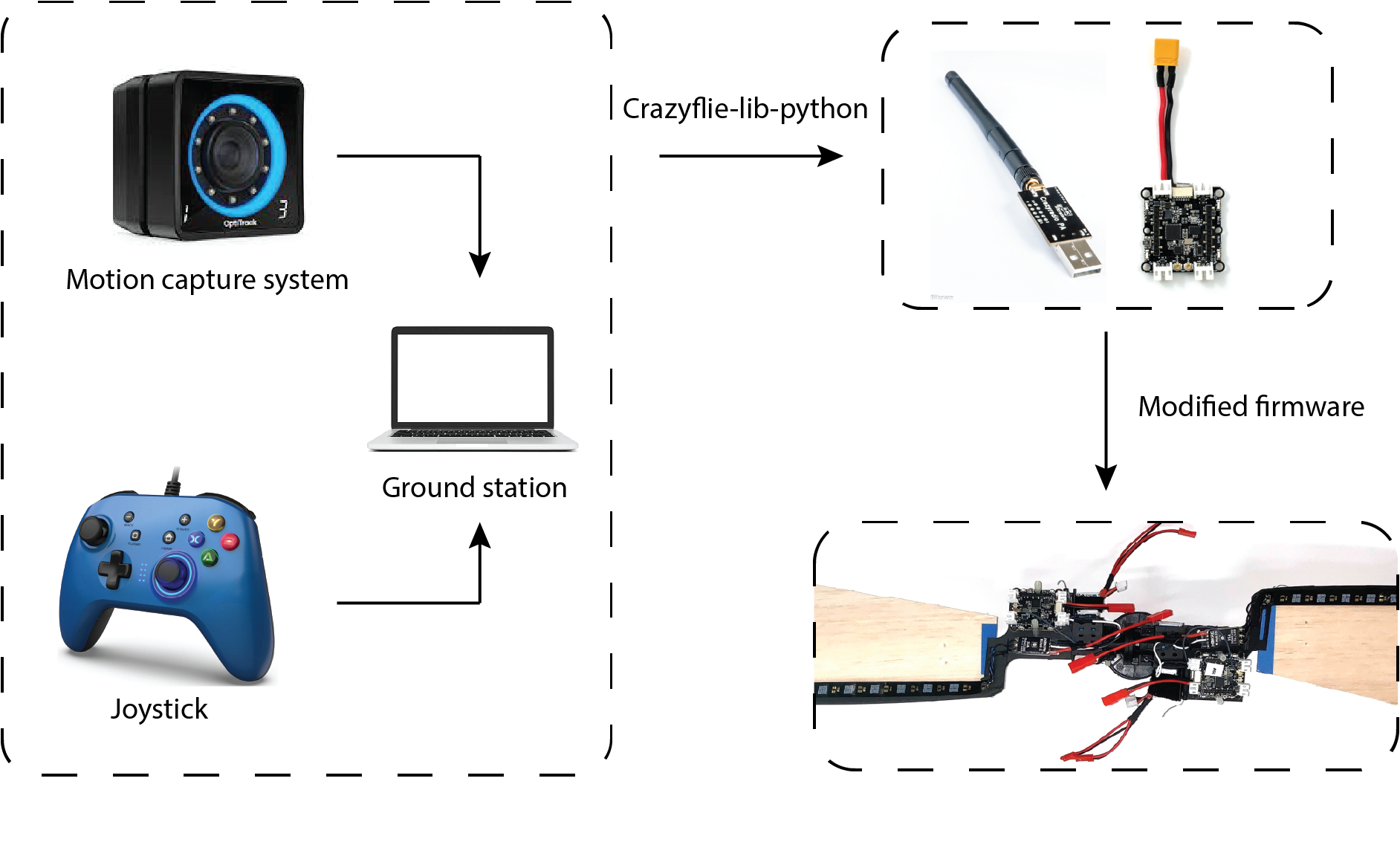
Thanks to its easy implementation and reliable performance, we use the Crazyflie Bolt as the flight controller for M-SAM. Like other robotic systems, the ground station is integrated with motion capture system (position and attitude feedback for both control and ground truth) and a joystick (control reference directly generated by user) is responsible for sending filtered state feedbacks and control references or control signal directly to flight controller. This is realized by employing the Crazyradio PA under the Crazyflie-lib-python environment. Simple modifications from the original firmware were made to map from the control reference to motor command (a customized flight controller).
A diagram shows how Crazyflie Bolts work in M-SAM project.
Another advantage of using Crazyflie Bolt in M-SAM project is its open source swarm library. Under the swarm environment, SAMs can fly in both singular and cooperative configurations. With simple human assistance, two SAMs can be assembled into cooperative configuration by making use of a pair of magnetic connectors. The mid-air separation from cooperative configuration to singular configuration is passively triggered by increasing the rotating speed until the centrifugal force overcomes the magnetic force.
Modular Single Actuator Monocopters (M-SAM), which is able to fly in both singular and cooperative configuration.
Potential applications
What kinds of applications can be achieved with the monocopter aerial robotic platform? On the one hand, many applications are limited by the nature of self-rotation motion. On the other hand, the passive rotating body also offers advantages in some special scenarios. For example, SAM is an ideal platform for LIDAR application, which usually requires the rotating motion to sense the environment around. Besides, thanks to simple mechanical design and cheap manufacturing cost, SAM can be designed for one time use such as light weight air deployment or unknown, dangerous environments.
An example [6] shows the potential applications of a rotating robot with camera.
Reference
[1] Ulrich, Evan R., Darryll J. Pines, and J. Sean Humbert. “From falling to flying: the path to powered flight of a robotic samara nano air vehicle.” Bioinspiration & biomimetics 5, no. 4 (2010): 045009.
[2] Fregene, Kingsley, David Sharp, Cortney Bolden, Jennifer King, Craig Stoneking, and Steve Jameson. “Autonomous guidance and control of a biomimetic single-wing MAV.” In AUVSI Unmanned Systems Conference, pp. 1-12. Arlington, VA: Assoc. for Unmanned Vehicle Systems International, 2011.
[3] Win, Luke Soe Thura, Shane Kyi Hla Win, Danial Sufiyan, Gim Song Soh, and Shaohui Foong. “Achieving efficient controlled flight with a single actuator.” In 2020 IEEE/ASME International Conference on Advanced Intelligent Mechatronics (AIM), pp. 1625-1631. IEEE, 2020.
[4] Win, Shane Kyi Hla, Luke Soe Thura Win, Danial Sufiyan, and Shaohui Foong. “Design and control of the first foldable single-actuator rotary wing micro aerial vehicle.” Bioinspiration & Biomimetics 16, no. 6 (2021): 066019.
[5] X. Cai, S. K. H. Win, L. S. T. Win, D. Sufiyan and S. Foong, “Cooperative Modular Single Actuator Monocopters Capable of Controlled Passive Separation,” 2022 International Conference on Robotics and Automation (ICRA), 2022, pp. 1989-1995, doi: 10.1109/ICRA46639.2022.9812182.
[6] Bai, Songnan, Qingning He, and Pakpong Chirarattananon. “A bioinspired revolving-wing drone with passive attitude stability and efficient hovering flight.” Science Robotics 7, no. 66 (2022): eabg5913.
Advancements in technology have made quadrotor drones more accessible and easy to integrate into a wide variety of applications. Compared to traditional fixed-wing aircraft, quadrotors are more flexible to design and more suitable for motioning, such as statically hovering. Some examples of quadrotor applications include photographers using mounting cameras to take bird’s eye view images, and delivery companies using them to deliver packages. However, while being more versatile than other aerial platforms, quadrotors are still limited in their capability due to many factors.
First, quadrotors are limited by their lift capacity, i.e., strength. For example, a Crazyflie 2.1 is able to fly and carry a light payload such as an AI deck, but it is unable to carry a GoPro camera. A lifter quadrotor that is equipped with more powerful components can transport heavier payload but also consumes more energy and requires additional free space to operate. The difference in the strength of individual quadrotors creates a dilemma in choosing which drone components are better suited for a task.
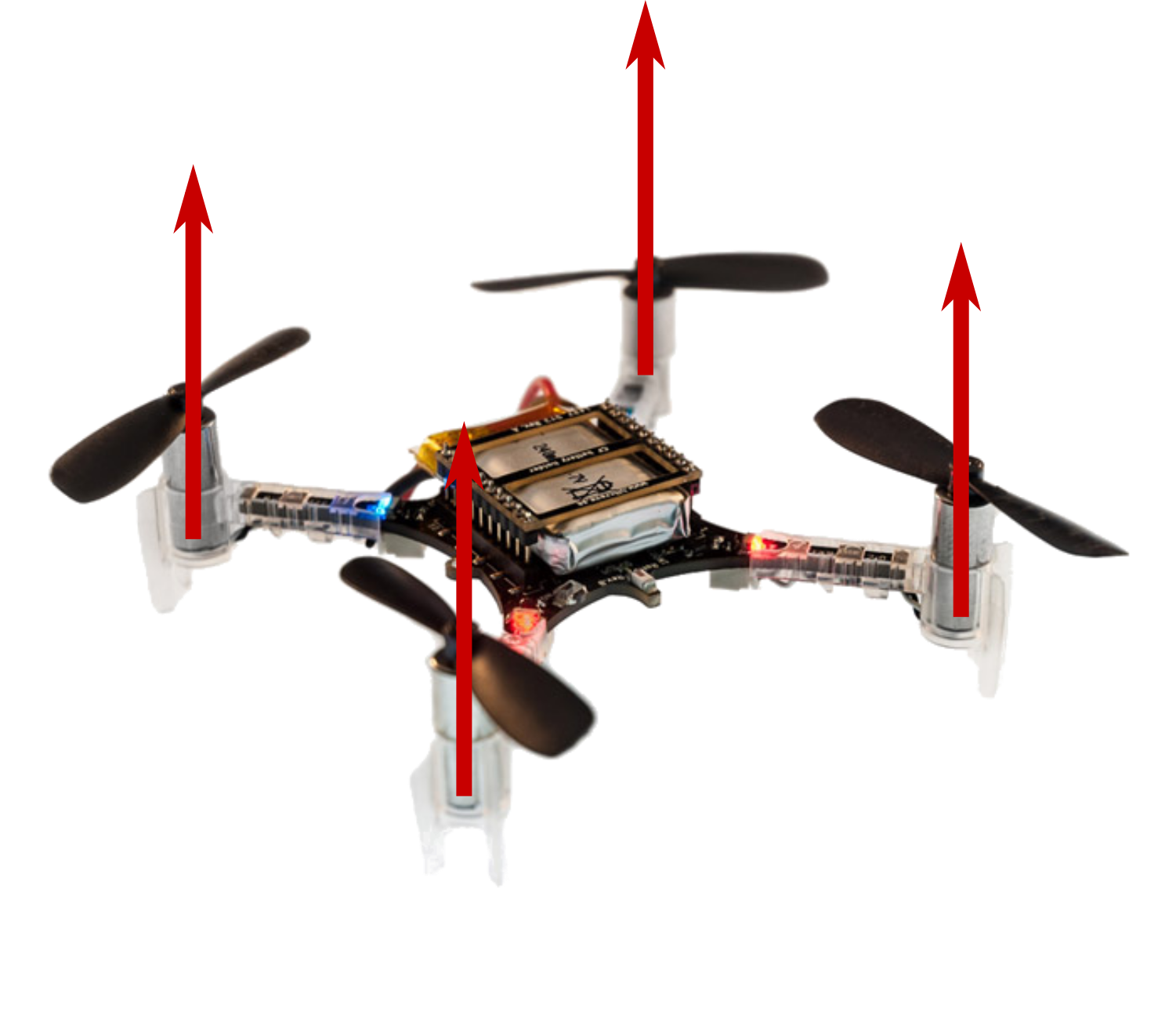
Second, a traditional quadrotor’s motion in translation is coupled with its roll and pitch. Let’s take a closer look at Crazyflie 2.1, which utilizes a traditional quadrotor design. Its four motors are oriented in the same direction – along the positive z-axis of the drone frame, which makes it impossible to move horizontally without tilting. While such control policies that convert the desired motion direction into tilting angles are well studied, proven to work, and implemented on a variety of platforms [1][2], if, for instance, we want to stack a glass filled with milk on top of a quadrotor and send it from the kitchen to the bedroom, we should still expect milk stains on the floor. This lack of independent control for rotation and translation is another primary reason why multi-rotor drones lack versatility.
These versatility problems are caused by the hardware of a multi-rotor drone designed specifically to deal with a certain set of tasks. If we push the boundary of these preset tasks, the requirements on the strength and controllability of the multi-rotor drone will eventually be impossible to satisfy. However, there is one inspiration we take from nature to improve the versatility in the strength of multi-rotor drones – modularity! Ants are weak individual insects that are not versatile enough to deal with complex tasks. However, when a group of ants needs to cross natural boundaries, they will swarm together to build capable structures like bridges and boats. In our previous work, ModQuad [3], we created modules that can fly by themselves and lift light payloads. As more ModQuad modules assemble together into larger structures, they can provide an increasing amount of lift force. The system shows that we can combine weak modules with improving the versatility of the structure’s carrying weight. To carry a small payload like a pin-hole camera, a single module is able to accomplish the task. If we want to lift a heavier object, we only need to assemble multiple modules together up to the required lift.
Improving controllability
On a traditional quadrotor, each propeller is oriented vertically. This means the device is unable to generate force in the horizontal direction. By attaching modules side by side in a ModQuad structure, we are aligning more rotors in parallel, which still does not contribute to the horizontal force the structure can generate. That is how we came up with the idea of H-ModQuad — we would like to have a versatile multi-rotor drone that is able to move in an arbitrary direction at an arbitrary attitude. By tilting the rotors of quadrotor modules and docking different types of modules together, we obtain a structure whose rotors are not pointing in the same direction, some of which are able to generate a force along the horizontal direction.
H-ModQuad Design
H-ModQuad has two major characteristics: modularity and heterogeneity, which can be indicated by the “Mod” and “H-” in the name. Modularity means that the vehicle (we call a structure) is composed of multiple smaller modules which are able to fly by themselves. Heterogeneity means that we can have modules of different types in a structure.
As mentioned before, insects like ants utilize modularity to enhance the group’s versatility. Aside from a large number of individuals in a swarm that can adapt to the different scales of the task requirement, the individuals in a colony specializing in different tasks are of different types, such as the queen, the female workers, and the males. The differentiation of the types in a hive helps the group adapt to tasks of different physical properties. We take this inspiration to develop two types of modules.
In our related papers [4][5], we introduced two types of modules which are R-modules and T-modules.
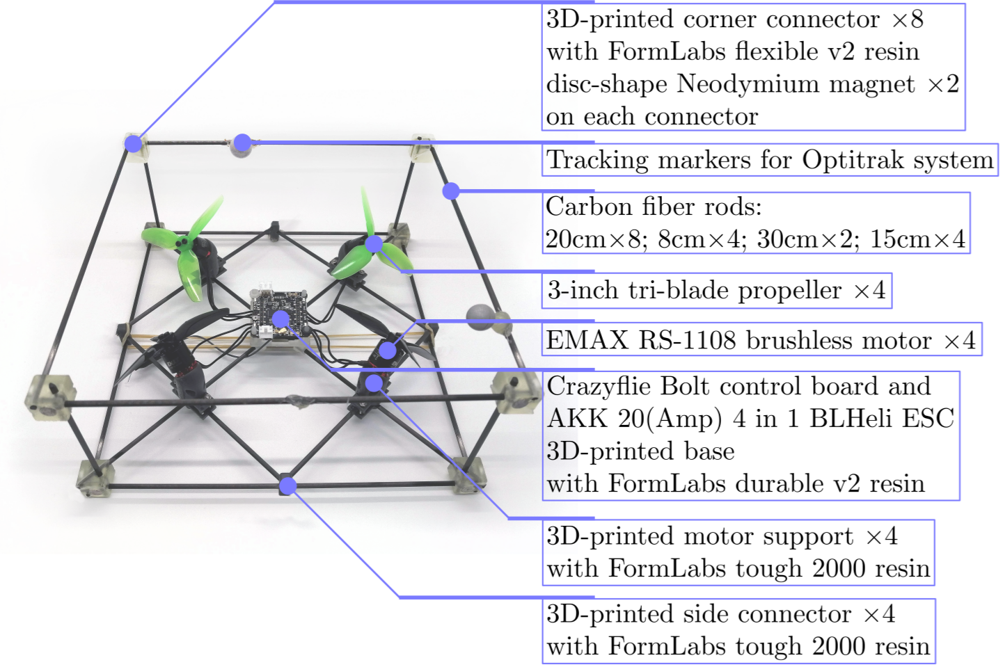
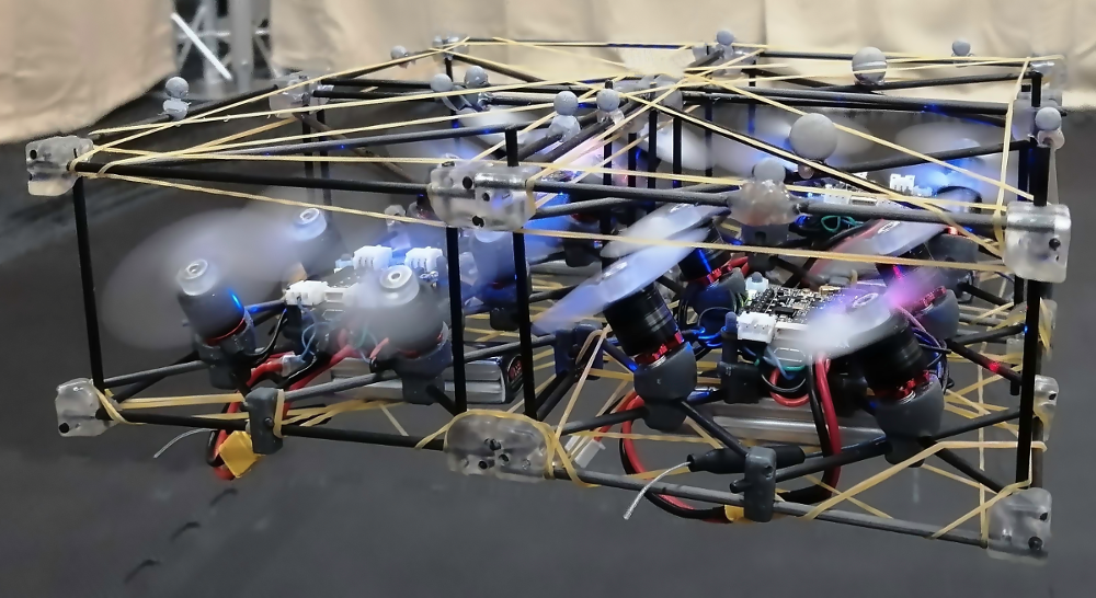
Fig 2. Major components of an H-ModQuad “T-module” we are using in our project. We use Bitcraze Crazyflie Bolt as the central control board.
An example T-module is shown in the figure above. As shown in the image, the rotors in a T-module are tilted around its arm connected with the central board. Each pair of diagonal rotors are tilted in the opposite direction, and each pair of adjacent rotors are either tilting in the same direction or in the opposite direction. We arrange the tilting of the rotors so that all the propellers generate the same thrust force, making the structure torque-balanced. The advantage of the T-module is that it allows the generation of more torque around the vertical axis. One single module can also generate forces in all horizontal directions.
An R-module has all its propellers oriented in the same direction that is not on the z-axis of the module. In this configuration, when assembling multiple modules together, rotors from different modules will point in different directions in the overall structure. The picture below shows a fully-actuated structure composed of R-modules. The advantage of R-modules is that the rotor thrusts inside a module are all in the same direction, which is more efficient when hovering.
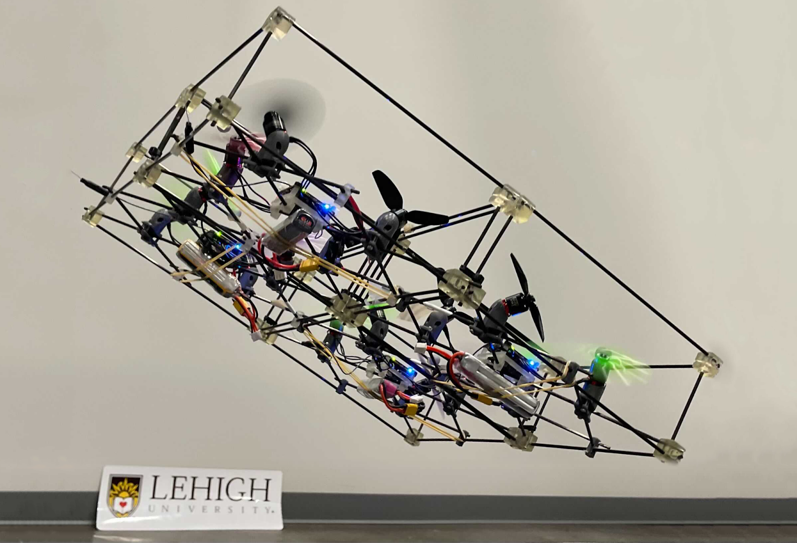
Structure 1: Composed of four types of R-modules.
Depending on what types of modules we choose and how we arrange those modules, the assembled structure can obtain different actuation capabilities. Structure 1 is composed of four R-modules, which is able to translate in horizontal directions efficiently without tilting. The picture in the intro shows a structure composed of four T-modules of two types. It can hover while maintaining a tilting angle of up to 40 degrees.
Control and implementation
We implemented our new geometric controller for H-ModQuad structures based on Crazyflie Firmware on Crazyflie Bolt control boards. Specifically, aside from tuning the PID parameters, we have to change the power_distribution.c and controller_mellinger.c so that the code conforms to the structure model. In addition, we create a new module that embeds the desired states along predefined trajectories in the firmware. When we send a timestamp to a selected trajectory, the module retrieves and then sends the full desired state to the Mellinger Controller to process. All modifications we make on the firmware so that the drone works the way we want can be found at our github repository. We also recommend using the modified crazyflie_ros to establish communication between the base station and the drone.
Videos
Challenges and Conclusion
Different from the original Crazyflie 2.x, Bolt allows the usage of brushless motors, which are much more powerful. We had to design a frame using carbon fiber rods and 3-D printed connecting parts so that the chassis is sturdy enough to hold the control board, the ESC, and the motors. It takes some time to find the sweet spot of the combination of the motor model, propeller size, batteries, and so on. Communicating with four modules at the same time is also causing some problems for us. The now-archived ROS library, crazyflie_ros, sometimes loses random packages when working with multiple Crazyflie drones, leading to the stuttering behavior of the structure in flight. That is one of the reasons why we decided to migrate our code base to the new Crazyswarm library instead. The success of our design, implementation, and experiments with the H-ModQuads is proof of work that we are indeed able to use modularity to improve the versatility of multi-rotor flying vehicles. For the next step, we are planning to integrate tool modules into the H-ModQuads to show how we can further increase the versatility of the drones such that they can deal with real-world tasks.
Reference
[1] D. Mellinger and V. Kumar, “Minimum snap trajectory generation and control for quadrotors,” in 2011 IEEE International Conference on Robotics and Automation, 2011, pp. 2520–2525.
[2] T. Lee, M. Leok, and N. H. McClamroch, “Geometric tracking control of a quadrotor uav on se(3),” in 49th IEEE Conference on Decision and Control (CDC), 2010, pp. 5420–5425.
[3] D. Saldaña, B. Gabrich, G. Li, M. Yim and V. Kumar, “ModQuad: The Flying Modular Structure that Self-Assembles in Midair,” 2018 IEEE International Conference on Robotics and Automation (ICRA), 2018, pp. 691-698, doi: 10.1109/ICRA.2018.8461014.
[4] J. Xu, D. S. D’Antonio, and D. Saldaña, “Modular multi-rotors: From quadrotors to fully-actuated aerial vehicles,” arXiv preprint arXiv:2202.00788, 2022.
[5] J. Xu, D. S. D’Antonio and D. Saldaña, “H-ModQuad: Modular Multi-Rotors with 4, 5, and 6 Controllable DOF,” 2021 IEEE International Conference on Robotics and Automation (ICRA), 2021, pp. 190-196, doi: 10.1109/ICRA48506.2021.9561016.
As the Crazyflie ecosystem expands, more and more novel aerial (but also ground or hybrid) robots are being built with one of the Crazyflie controllers onboard. For recent examples, you can check e.g. the recent blogpost about ICRA 2022.
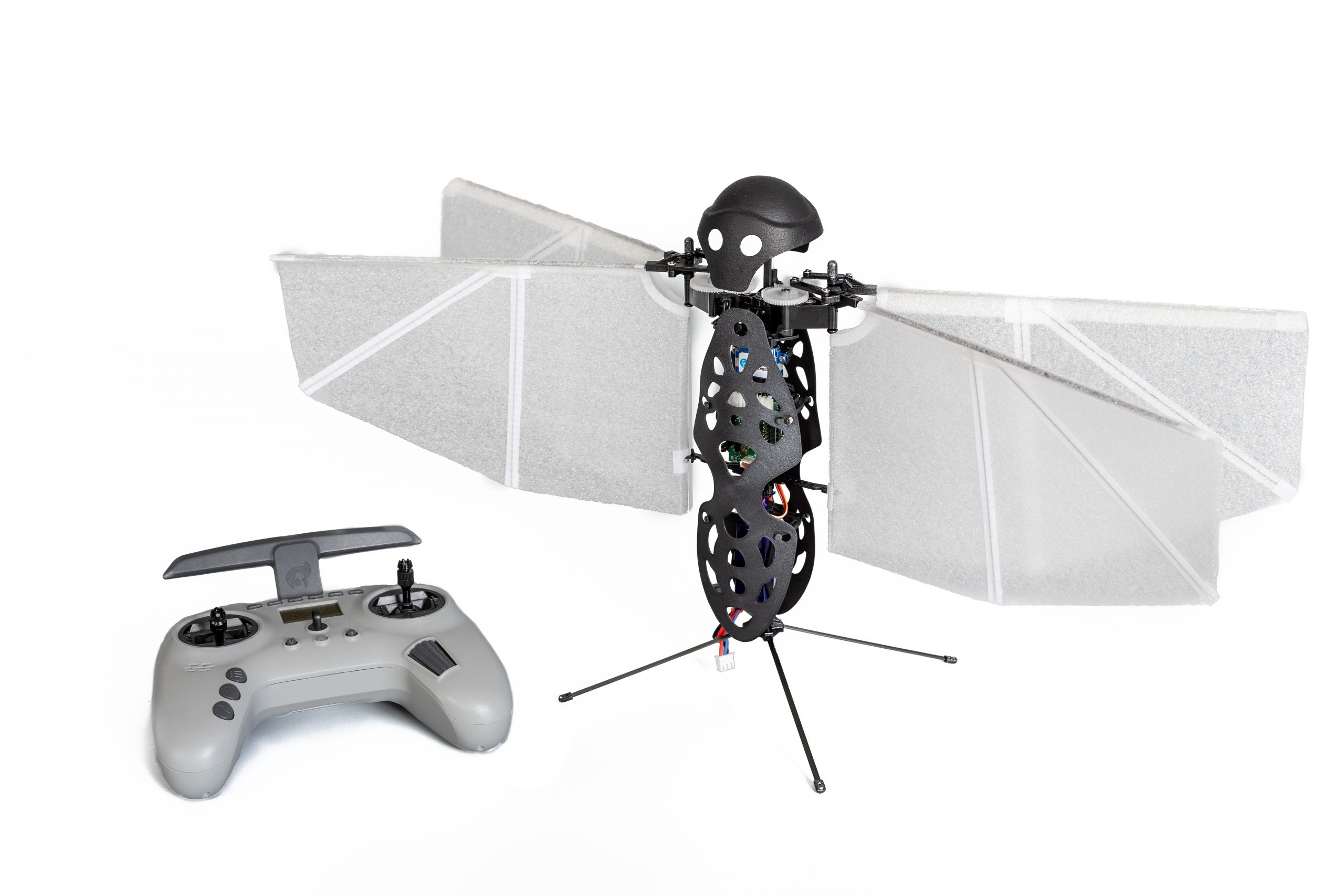
In this post, I will introduce yet another Crazyflie-Bolt-powered aerial robot, the Flapper Nimble+ from our company Flapper Drones, which unlike other flying robots doesn’t have any propellers but uses flapping wings instead.
The best aerial robot design is…
Small drones, or micro air vehicles, have seen a lot of progress and new developments in the last 20 years. The most widespread design nowadays is a quadcopter, such as the Crazyflie 2.1. But is a quadcopter the ultimate (micro) drone solution? At Flapper Drones, we believe nature might provide even better designs… For some applications at least! ?
Flying like a bird…
Flapper Drones is a spinoff of the MAVLab of the Delft University of Technology. At the MAVLab, we have been researching bio-inspired flight as part of the DelFly project since 2005. From the beginning, the goal has been to develop a lightweight, mission capable micro air vehicle, the design of which would draw inspiration from nature. Over the years, many such MAV concepts have been designed, built and tested, including the DelFly Micro, the world’s smallest camera-equipped MAV, or the DelFly Explorer, the first autonomous flapping-wing MAV equipped with a stereovision system. All these designs were propelled by a pair of flapping wings, while being controlled (and passively stabilized) by a tail such as birds or men-made airplanes.
… or an insect
The latest design, the DelFly Nimble is insect-inspired instead. What does that mean? The Nimble has no tail, which would provide the damping needed for stable flight. Instead, it is stabilized actively, by adjustments of the motion of its flapping wings. This is what all flying insects and also hummingbirds do. Flies, for example, sense their body motions with their halteres, drum-stick like biological gyroscopes, and adapt their wing motion accordingly to stay balanced…. or to be agile, when someone is trying to swat them!
And while the Nimble was originally built just to demonstrate that an insect-inspired flying robot can be built, eventually we could also use it to learn more about the flight of insects:
Flapper Drones – how do they work?
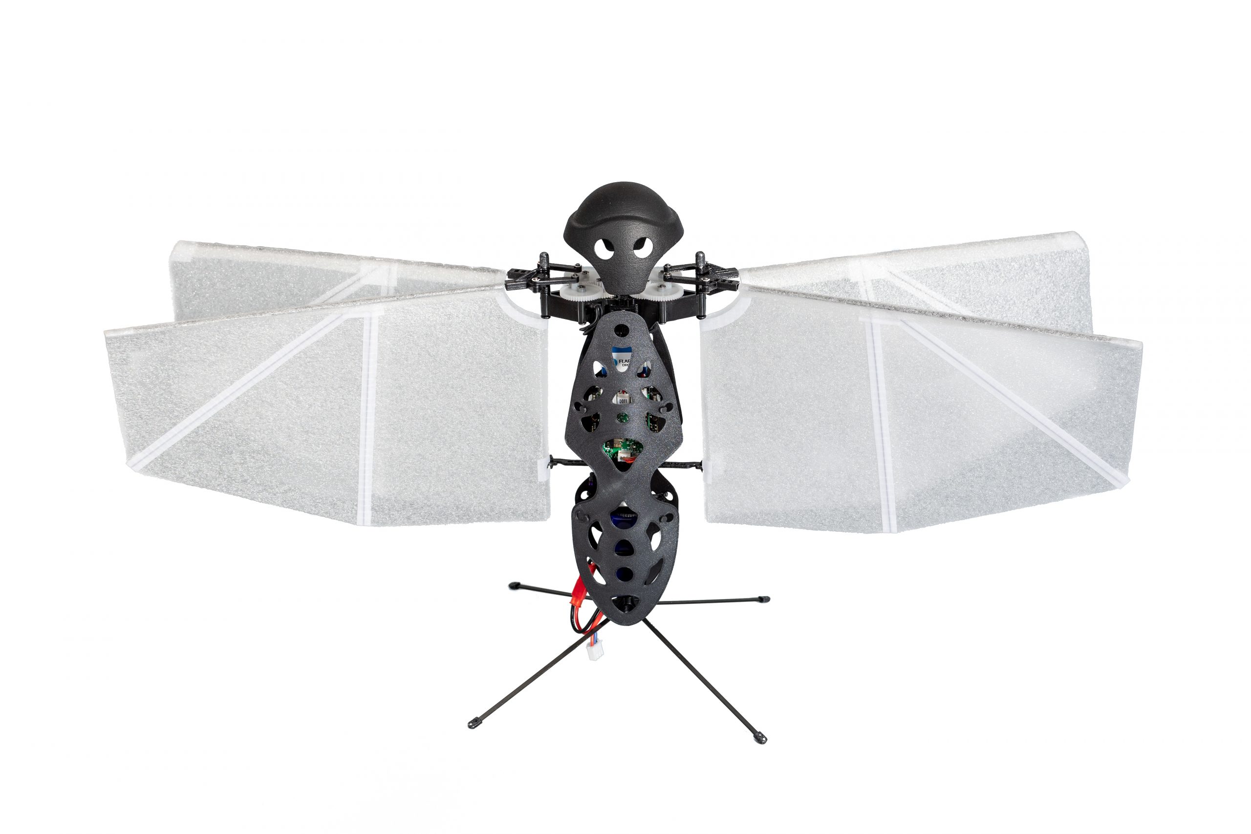
The Flapper Nimble+ is the commercial (and enlarged) version of the DelFly Nimble, developed and produced by Flapper Drones. To our knowledge, it is the first, and so far the only hover-capable tailless flapping-wing drone available!
The thrust keeping the Nimble+ airborne is created by its four flapping wings, which flap back and forth horizontally, about 10 to 12 times per second.
The wing actuation mechanism allows to adjust the flapping frequency of the left and right wing pairs independently, which enables control of the roll rotation. Pitch rotation is controlled by adjusting the mean wing position within the stroke plane, which shifts the mean thrust force forward or backward with respect to the center of mass, and also introduces a stabilizing dihedral angle in forward flight. Finally, yawing motion is achieved by tilting the wing roots of the left and right wing pair asymmetrically:
Advantages of flapping wings
The use of flapping-wing drones such as the Flapper Nimble+ brings several advantages. Next to their attractive biological appearance, the soft flapping wings produce less intrusive, low frequency sound and are safer, compared to propellers. As the wings move back and forth, minor mid-air collisions are not a problem. The wings bounce off objects leaving no damage, and the drone keeps flying as this only represents a minor disturbance:
The aerial drag characteristic is also different and helps with precise indoor flight. As soon as zero attitude is commanded, the Nimble+ goes into halt in a matter of several wingbeats, making it an ideal choice for novice drone pilots as well as in constrained or cluttered indoor spaces. Finally, the flapping wings can provide additional lift force as they also glide in forward flight. This can improve the power efficiency by over 20%, compared to hovering.
Otherwise, Flapper Drones can be operated as any other drone, with vertical take offs and landings, quick maneuvers and flight in any direction:
Crazyflie Bolt & compatibility
The Flapper Nimble+ is powered by the Crazyflie Bolt 1.1, where the Bolt’s BMI088 IMU and STM32F4 MCU are suitable substitutes to the halteres and brains of the real fly. We made this choice, because this enables compatibility with most of the Crazyflie ecosystem, but also, because we felt the only way a Crazyflie would do justice to its name is if it had flapping wings?
Currently, the Nimble+ uses a fork of the Crazyflie firmware, which is of course open source. Moreover, with the recently introduced platform functionality, we will be able to include the Flapper platform into the official crazyflie firmware very soon (expected still in July 2022). This means that the Flapper remains compatible with the official Python libraries, the PC client or the smartphone app. But also third-party projects like the Crazyswarm or the Skybrush should only require minor adjustments, if any, to operate a swarm of Flappers. Thus, for the existing Crazyflie users, switching from a Crazyflie to the Flapper should be a breeze!
The Flapper Nimble+ is hardware compatible with most of the Crazyflie expansion decks. While software support remains experimental (the Flapper Nimble+ is not a native Crazyflie product, after all), many of the decks work out of the box and others might need just minor firmware modifications. Would you like to fly the Nimble+ autonomously? Add an LPS or Lighthouse deck and you’re good to go!
For more details regarding deck compatibility, you can check this overview.
Applications
While the Nimble+ was originally designed for drone shows and similar entertainment applications, the open-source firmware and expansion decks enabling autonomous flight make it ideal also as for academic research and, in general, as a development platform. Are you researching swarming, and would you like to make your swarm even more bio-inspired? Are you developing new sensors, or new controllers (possibly even bioinspired), which you would like to test on a new type of flying platform? Are you interested in the aerodynamics of flapping wings, or the flight dynamics of insect-like flight? Or are you just curious and would you like to learn more about bioinspired flight? In all these cases, a Flapper might be what you are looking for!
The 114-g and 49-cm wide Flapper Nimble+ has been designed as a modular system where any part can easily be replaced. Flapper Drones provides all the spares, which are available upon request. If you are interested in using the Nimble+ for entertainment, rather than research, you can modify the appearance by creating your own body shells, which can also be illuminated by RGB Leds (a suitable interface and power supply is already integrated). Or even by altering the design of the wings. Finally, you can easily extend the Flapper with your own sensors, or other devices. Would you like to add a tail? A gripper? A perching device? This is all possible, as long as these additions fit within the payload limit of about 25 grams.
Available soon in the webstore!
Did you get (bio)inspired, and would you like to try an insect-like flying robot yourself? Then we have some good news! The Flapper Nimble+ will soon be available for sale in an exclusive partnership with Bitcraze and their webstore. Checkout the product description and leave your email address behind, such that you get a notification when the Flappers are in stock and ready to ship. The first batch of 10 units is expected to be available at the end of summer, so do not wait too long ?
Want to learn more?
To learn more about Flapper Drones, you can check our website, or watch the talk I gave at the last miniBAM:
This week, we welcome Airi Lampinen from Stockholm University, to talk about the Crazyflie competition she’s organizing in Stockholm.
Welcome to our one-of-a-kind hackathon with Bitcraze’s Crazyflie in Stockholm, Sweden, on June 15-17, 2022! If you are curious about how technology and humans may play together, enthusiastic about the Crazyflie, or eager to learn how to use the Crazyflie, this event is for you.
Image credit: Paul Bechat, ETH Zurich
What, where, when?The Inaugural Challenge at the Digital Futures Drone Arena takes place on June 15-17, 2022 at KTH’s Reactor Hall – a dismantled nuclear reactor hall – which – especially if you haven’t been to this cool space before – makes attending the event worthwhile in its own right. In 2016, the reactor hall was used to film the music video for Alan Walker’s song Faded (Restrung).
Who can join? Anyone irrespective of age, profession and past experience with drones is welcome to participate. We welcome up to 10 teams of 2-4 people. We provide all the necessary drone hardware to the participants. We use the Crazyflie 2.1 and the Lighthouse positioning system. All that a team needs to bring along is a computer. Registration is open, with a final deadline on June 5 – we encourage those interested to sign up as soon as possible to secure their spot!
Program & prizes? On the first day of the hackathon, we will run short tutorials for those with no or little previous drone experience. The teams will then have access to the Reactor Hall to work on the challenge and conduct trial runs with their drone – we offer long hours but each team is free to choose how much they want to work. (The goal here is to have a good time!) The competition itself takes place on the third and final day. We’ve got exciting prizes for the most successful teams!
We have also some Bitcraze news to share with you:
Last wednesday, we had our very first mini BAM, and it led to 2 hours of interesting talks and exciting discissions ! If you’ve missed it, you can find the recordings in your Youtube Channel: here for Flapper Drones’ presentation, and here for Collmot‘s talk. We plan on having at least one another mini BAM before the end of the year, so stay tuned if you’re interested in those events.
Finally, as I talked about in this blogpost, we are looking for a new team mate to add to the Bitcraze crew. You’re interested? Check out our jobs page if you want to learn more !