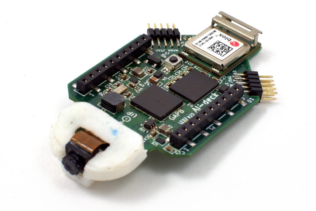
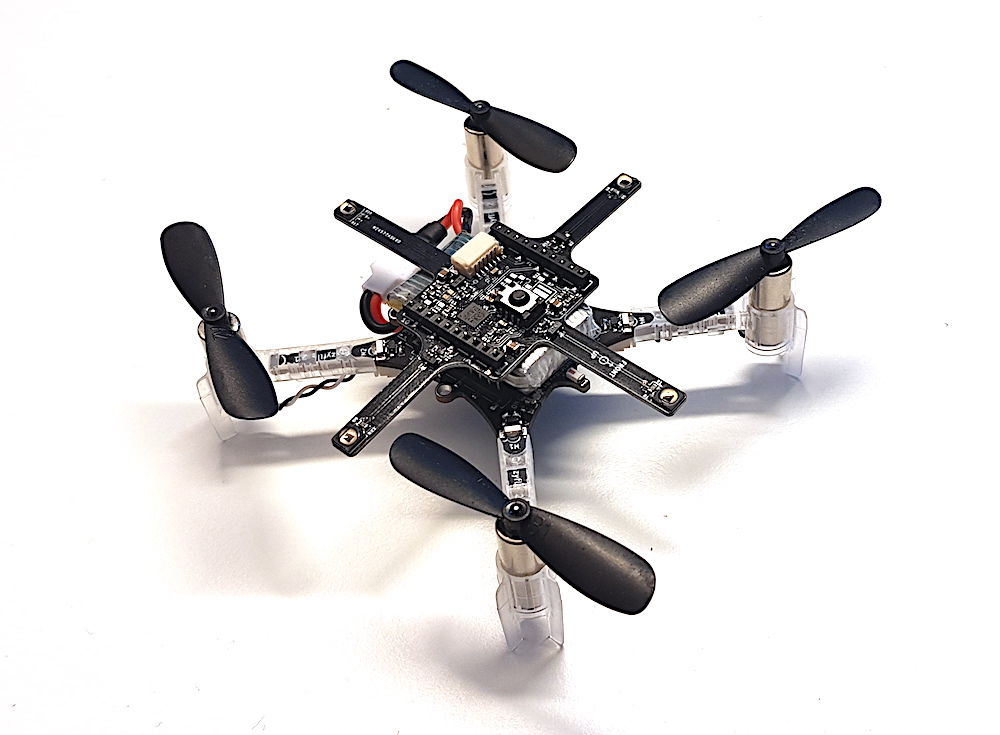
As pointed out in Daniele’s blog post about the PULP-DroNet we are collaborating on a AI-deck built around the new GAP8 RISC-V multi-core MCU. In the blog post you can find all the details around DroNet while here we will talk a bit about the AI-deck hardware. The AI-deck is similar to the PULP-Shield but with some optimizations. One of the HyperFlash memory spots has been removed, the communication interface slimmed down and a ESP32 (NINA module) has been added for WiFi connectivity.
Latest AI-deck prototype
So all together this a pretty good platform to develop low power AI on the edge for a drone.
Features:
GAP8 – Ultra low power 9 core RISC-V MCU
Himax HM01B0 – Ultra low power 320×320 greyscale camera.
512 Mbit HyperFlash and 64 Mbit HyperRAM
ESP32 for WiFi and more (NINA-W102)
2 x JTAG for GAP8 and ESP32
Currently we are doing the final testing of the hardware and hopefully we will launch production in the end of October. If production goes according to plan we hope we can offer it as an early access product just before X-mas. Make sure to come back and check the blog for more information about the progress as well as pricing.
We are happy to announce that we have made new official releases of a number of our software components. The name of the release is 2019.09 and we have outlined the main changes below.
Crazyflie/Roadrunner firmware
Added support for the Crazyflie Bolt
Improved support for external positioning systems
Basic support for the Lighthouse positioning system
The Crazyflie Bolt and the Crazyflie 2.1 with the lighthouse deck are coming to Madrid!
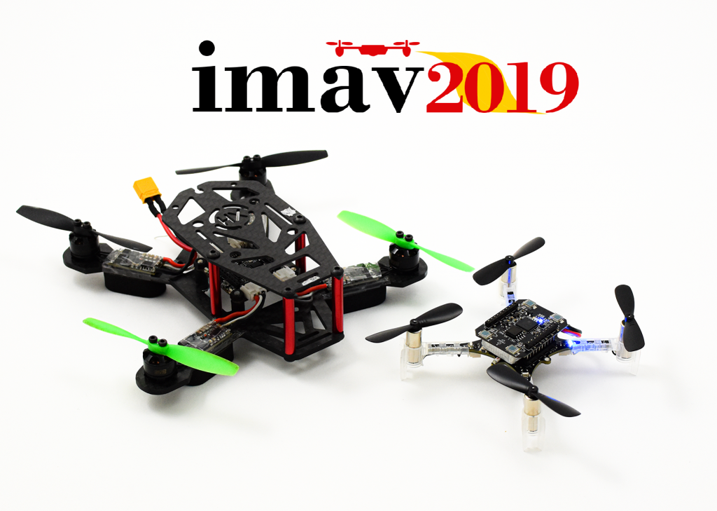
Only one week away until the start of the big Bitcraze Conference frenzy, with the first stop… Madrid! We will visit the Micro Air Vehicle Competition and Conference, which is a robotics event that is more specialized in (as the name implies) MAVs! So it should be right up our alley. This is the first time that we attend as Bitcraze, although the writer of this blog post has experienced fun times at the conference and the competition as a participant with her previous lab, the MAVlab.
The IMAV has been around for almost 12 years, starting in Toulouse, France in 2007. Although it initially mostly was held in various places in Europe, in 2016 into a more worldwide phenomenon by making it’s tribute in Beijing, China and Melbourne, Australia in 2018. It hosts a conference to which researchers can send their work in anything related to MAVs, from autonomous navigation, state estimation and design.
IMAV is mostly know for hosting big indoor and outdoor competitions for MAVs. The outdoor competitions can range from survey tasks to finding a hidden person or object. This year the focus will be on the delivery of packages from one place to another. The judges will look at how many packages that can be safely delivered and if the drone is able to detect certain objects in the outdoor environment. The indoor competition is oriented around the application of MAVs in a warehouse. They should be able to take off autonomously, monitor boxes in shelves and make an innovatory, and pickup packages to release them in their designated location. 40 teams of 28 universities will show their awesome implementation in these difficult tasks.
We will have a booth at the main company fair at the conference and indoor competition, and will also be present at the outdoor competition day as well. We will bring the lighthouse positioning system and show the awesome swarming demo we developed. Also we want to bring the new Crazyflie Bolt with us, which we are sure of that the regular IMAV crew will love. If you are at the IMAV between the 30th of September to the 4th of October, come by and say hello!
We have referred to Fun Fridays in a number of posts in this blog, but recently realized that we never described what it is about. Hopefully that will be rectified in this post.
The concept is simple: on Fridays we do what ever we want to, as long as it is fun, interesting and (at least remotely) connected to Bitcraze. It might be trying out a new technology, play with a new sensor, create new functionality, design a prototype board or similar. Our belief is that playing is key to being creative and that creativity is beneficial to the employees as well as to the company.
There are many other companies that have similar concepts, though most of them might not go as far as reserving 20% of the time for it. For us this was a simple choice since we’re all really passionate about technology and like to explore new things.
We’ve tried to implement this in previous work environments and also talked to other companies about it. Most of the time it comes down to two things, trust and money. The concern that employees will not do useful things and this will waste company resources (i.e money). For us this isn’t really an issue. First of all we work in a way where everyone is involved and takes responsibility for the company, so we trust everyone on the team. Secondly the idea behind Bitcraze is to create a workplace where we want to work. The idea has never been to optimize on profit but instead create a sustainable company that shares the values and direction of the team.
Even though we do not prioritize higher profits, it turns out that time when employees can make their own choices are very good from a business point of view as well. It has been said that 3M has a similar concept where they invest 15% of the time into “free” projects, and that 85% of the revenue today comes from these projects!
Looking back it has also been a good deal for Bitcraze, a lot of our products (actually most of them) and internal systems have been started on Fun Fridays. A few examples are the LPS, the Lighthouse and the Multiranger deck as well as the Bolt. There is also a (large) number of prototypes in our drawers that never made it into products, not to mention the happiness it has created!
Working at Bitcraze means designing electronics as well as writing software for it, but there is also a lot of other things going-on and managing servers is one of them.
Originally, in 2011 we had a virtual server in the cloud (a VPS like it was called back then). We carefully setup and configured this server and we maintained it over the years. This was easy and served us well but it was also very ‘manual’: any updates where done on the production machine directly and we where doing all changes directly in the production machine.
In 2015, when Kristoffer joined Bitcraze, he revamped completly the server setup. Suddenly we had not only one server but two, one production and one staging. And all servers running on these machines where running in docker containers. This means that the servers where nothing more than a well configured machine to run docker, and all important software and configuration are in docker images and are launched using docker-compose. This is the architecture we are still using today, a great description was written by Kristoffer in a previous blog post.
The docker architecture has worked well but we still have one major problem, we still have servers to take care of. They are still configured manually, needs to be kept up to date and happy at all time. We have been wanting to get rid of these servers and “just” run our containers.
Now enter Kubernetes. Kubernetes is a container Orchestrator originally made by Google that abstracts the servers and allows to run containers independently of handling servers. We had heard of Kubernetes back when we started working with Docker but deemed it overkill: we did not want to setup and handle a cluster of server by ourselves and back then it was not clear that how long Kubernetes would be around. Over time though Kubernetes has had support by all major cloud providers and there is managed offers that would allow us to not handle any servers ourselves.
We are not there yet, but we have been working over the summer at converting our infrastructure to Kubernetes and we are very close to deployment. One of the main parts is our internal Jenkins build server that currently build and deploy services by ssh-in into servers. With Kubernetes this deployment phase will be much simpler and will allow us to update the website without downtime, this is a welcome functionality now that the documentation is moved from the wiki to the main website.
With lightweight Kubernetes distributions like K3S there is also an opportunity to run containers in more domains. For instance we have been talking about making automated hardware system test-bench for a while to test every commit against the real hardware. With K3S and a couple of raspberry-pi that could be achieved quite easily. This is a subject for future fun Fridays though … :-).
We have briefly mentioned the Active marker deck earlier in our blog and in this post we will describe how it works and what it is all about.
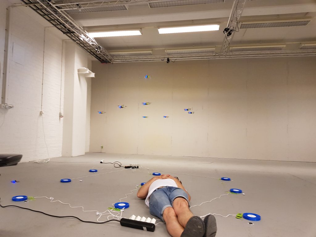
The Active marker deck is a result of our collaboration with Qualisys, a Swedish manufacturer of high end optical tracking systems. Optical tracking systems are often referred to as motion capture (mocap) systems and are using cameras to track markers on an object. By using multiple cameras it is possible to calculate the 3D position of the markers and the object they are attached to with very high precision and accuracy. It is common to use mocap systems in robotic labs to track the position and orientation of robots, for instance quadrotors.
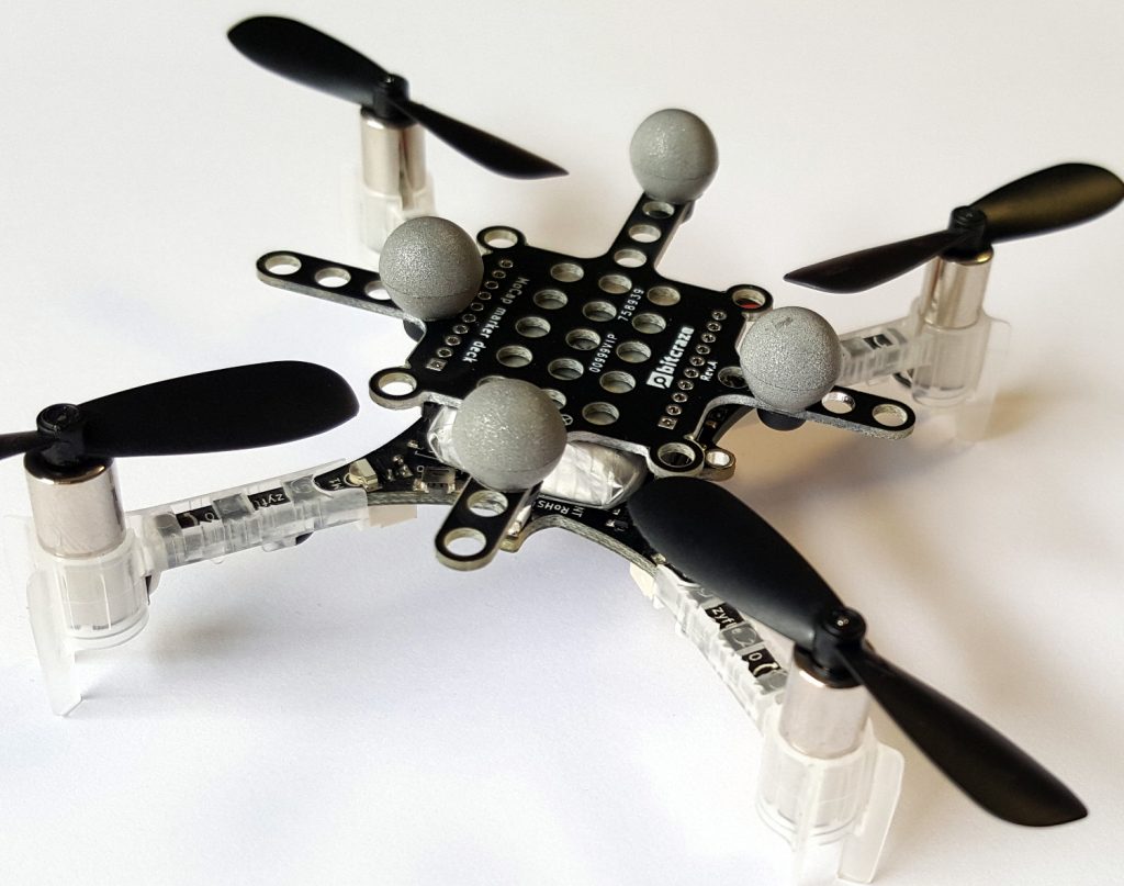
Passive markers
The most common marker type is the passive marker, that is reflective spheres that are attached to the robot. By using infrared flashes on the cameras, the visibility of the markers is maximized and it makes it easier for the system to detect and track them. We are selling the Motion capture marker deck to make it easy to attach markers to a Crazyflie.
To get the full pose (position, roll, pitch, yaw) of a robot, the markers must be placed in a configuration that makes it possible for the mocap system to identify the orientation. This means that there must be some asymmetry in the marker positions to understand what is front, back, up, down and so on.
With a swarm of Crazyflies, unique marker configurations makes it possible to distinguish one individual from another and track all drones simultaneously. With a larger number of robots it becomes cumbersome though to place markers in unique configurations, and one approach to solving this problem is to have known start positions for all individuals and keep track of their motions over time instead. This solution is used in the Crazyswarm for instance and all Crazyflies can use the same marker configuration in this setup. Another approach is to make it possible to distinguish one marker from another, enter the Active marker deck.
Active markers
It is possible to use infrared LEDs instead of the passive markers, this is called active markers. The LEDs are triggered by the flash from the cameras and they are easily detected as strong points of light. Since they are emitting light they can be detected further away from the camera than a passive marker and the smaller physical size also keeps them more separated when they are far away and only a few pixels are available to detect them in the camera.
Furthermore Qualisys has a technology that makes it possible to assign an id to each marker and that enables the tracking system to identify individual markers and thus uniquely identify individuals in a swarm. With different IDs on the markers, there is no need have asymmetrical configurations and the marker layout can be the same on all drones. It also reduces the risk of errors in the estimated pose, since there is more information available.
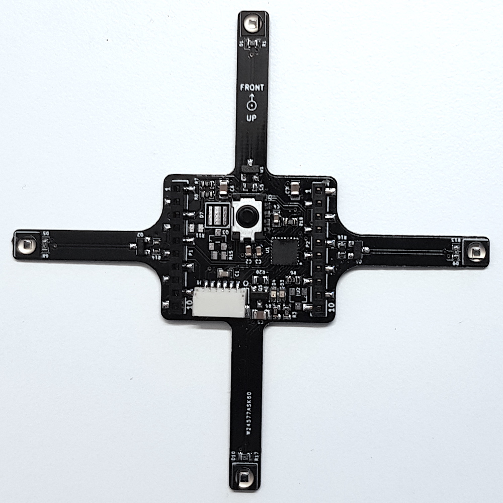
The deck
The Active marker deck is designed to go on top of the Crazyflie and has four arms with one LED each. The arms are as long as possible to maximize the signal/noise ratio in the cameras, while still short enough to be protected from crashes by the motors. There is a STM32 F0 on the deck that takes care of the LEDs and handling of IDs and the main Crazyflie CPU does not have to spend any time on this.
The status of the deck is that the hardware is fully functional (we might want to move something around before we produce it though) and that there is a basic implementation of the firmware. IDs are assigned to the markers using parameters in the standard parameter framework in the client or from a script.
We will start production of the deck in the near future and it will be available in the store this autumn. Qualisys added support for rigid bodies using active markers in V2019.3 of the QTM tracking software.
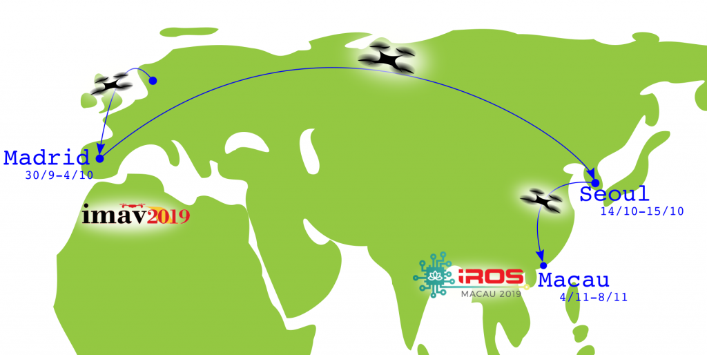
We have a busy schedule in the fall, since we are planning to travel all around the world for all kinds of awesome conferences and symposia. Here is a quick overview of where we are planning to go in October and November.
IMAV Madrid 1/10-4/10
We will attend the IMAV 2019, and this time it is in Madrid (Spain) from the 1th to the 4th of October. This is a conference for anything related to micro-aerial vehicles and also includes an awesome indoor and outdoor competition. Arnaud and Kimberly will be present at both the indoor and outdoor fair, where we will show some demos with the lighthouse system and show off our new Crazyflie Bolt!
In collaboration with our partner CLRobur, we will have a symposium in Seoul (Korea) on the 14th and 15th of October. Kristoffer will explain the attendees all about positioning systems, and show off the LPS and our new lighthouse deck.
Sign up here or send an email to clrobur@naver.com
IROS Macau 4/11-8/11
Last but not least, we will be there at IROS 2019 as well! This is one of the flagship robotics conferences of IEEE. In Macau (China) from the 4th till the 8th of November, Marcus and Tobias will show some awesome demos with the lighthouse system and hopefully we will present the new AI deck!
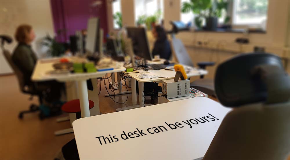
We have so many interesting things we want to do, but too little time to do it. Now we are looking for more talented people to join our team to help us create awesomeness!
We don’t have a clear description of exactly what we are looking for but there are some properties that we think are important:
You are interested in technology
You are passionate
You want to learn new things and evolve your skills
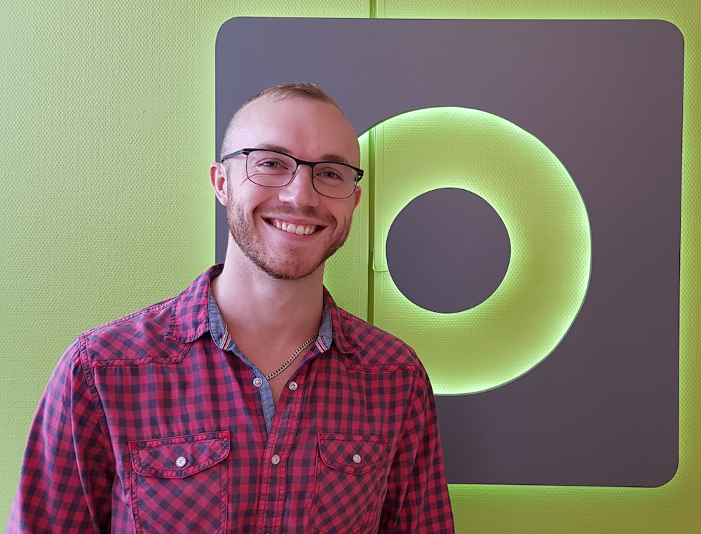
Hello everyone, I’m Victor and you probably haven’t heard of me yet but I’ve got the awesome opportunity to spend some weeks during this summer working at Bitcraze. Working… Well, I’ve spent the majority of my time here getting invaluable experience, programming, flying with drones, eating incredible falafel and having fun so it’s really been a pleasure.
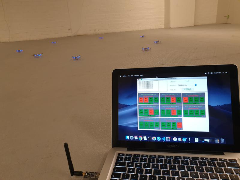
I’m quite new to both programming and electronics, so while I haven’t created any huge masterpieces of code yet, I did make a small program with a GUI that let you test the health of motors and propellers of the Crazyflie. You can run multiple ones simultaneously (I’ve tried up to 8, which works fine, even with a single radio, and you should be able to run many more) and it relies on using either Lighthouse or a Flow deck for positioning. The propeller-test is essentially the same test as the one integrated with the cfclient, however the motor-test checks the thrust-levels of the motors (by hovering in the air for x seconds) to see if any of them are off and ranks them as good/bad. The default threshold is 15% but can be changed according to needs. The program is written in Python and uses tkinter to run the GUI application and the cflib to communicate with the Crazyflie. The script can be found here.
In the end of August I’m going to study Computer Science and Engineering which I’m extremely thrilled about and this has really been a perfect preparation for that! In the future I hope to contribute to the Crazyflie projects and learn more from the great team here at Bitcraze.
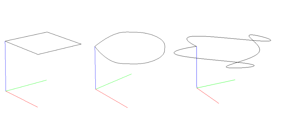
The High-level Commander has been part of the Crazyflie firmware since the 2018.10 release. In combination with a positioning system, it can fly the Crazyflie along a trajectory that is either defined in the firmware or uploaded through the python lib. It originates from the Crazyswarm project and we have used it in various demos since it is possible to make trajectories that are very fluid and looks really cool. The trajectories are defined as 7th degree polynomials describing segments executed one after each other.
The controller gives full control of position, velocity, acceleration and jerk, the only problem is that it is non-trivial to generate the polynomials. We have wanted to simplify the creation of trajectories for a long time and have finally had some time to play with it. In this blog post we will describe how it can be done with Bezier curves and show some examples.
Each segment in a High-level commander trajectory is defined by four 7 degree polynomials, one for x, y, z and yaw. There is also a scaling parameter that tells the controller the time scale to use when executing the segment. Using polynomials of degree 7 makes it possible to design trajectories that are continuous in position, velocity, acceleration and jerk when changing from one segment to the next, which is important to get a smooth and controlled flight.
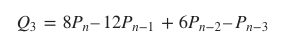
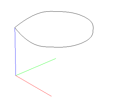
Bezier curves are common in many graphics applications and are probably known to most users. They are parametric curves defined by control points, usually three or four. Bezier curves can also be expressed as a polynomial, and this is what we will use in this case. To get a correct mapping to the desired polynomials we need some more control points and will use 8 per segment. The basic idea is to define the trajectory as Bezier curves and make sure the control points are placed in such a way that the continuity requirements are satisfied.
Bezier curve with 8 control points
On this page from University of Cambridge, there is a good explanation on continuity across the joins between curves and formulas for c0, c1 and c2 continuity. We also need c3 continuity which can be calculated in the same manner
With these formulas it is possible to set the handles of the Bezier curves to make sure we get a smooth ride.
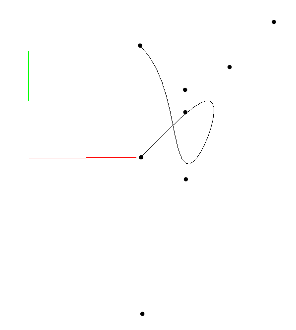
We have added a python example that implements the ideas above. You can find it in crazyflie-lib-python/examples/positioning/bezier_trajectory.py. The design is based on Nodes that represents the connection points between bezier curves (called Segments). The Nodes has a set of handles that are shared between the Segments that use the Node. If not all handles are set the implementation will set them to appropriate values, see the comments in the code for more details. The Node API only allows the user to set handles on one of the Segments, the handles for the other segment are automatically set to generate a continuous trajectory.
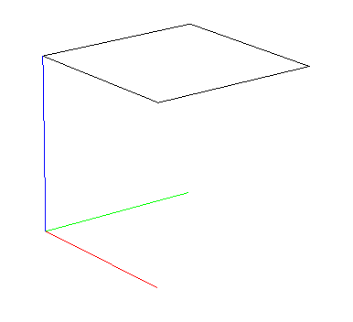
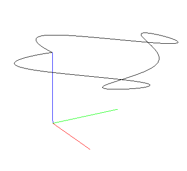
The example uses nodes in the corners of a square and contains three parts:
No velocity in the nodes. The Crazyflie stops in the Nodes. Similar to calling go-to in the HL commander.
Velocity in the nodes. A fluid motion all the way around.
Velocity in the nodes. A fluid motion all the way around.
A bit more aggressive settings to get a little action.
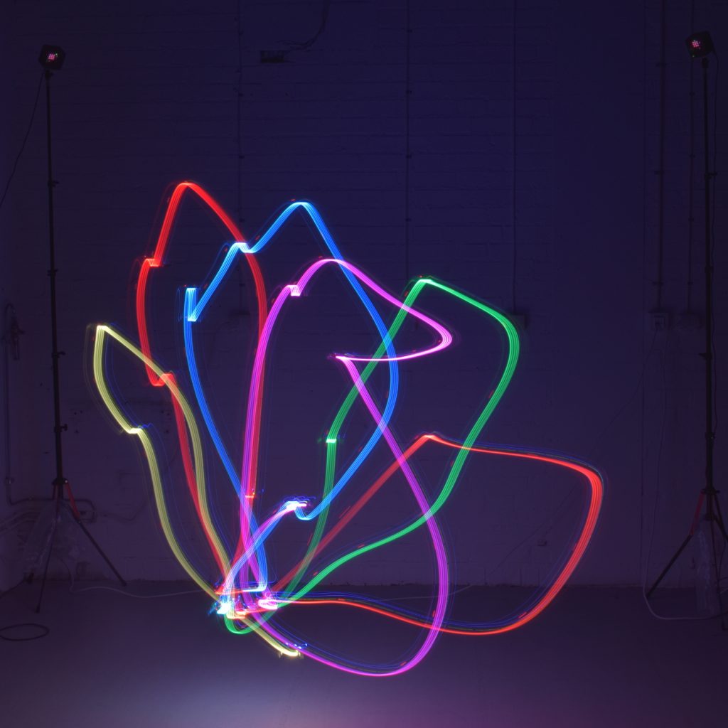
Finally a video showing the full sequence, we use the Lighthouse for positioning.