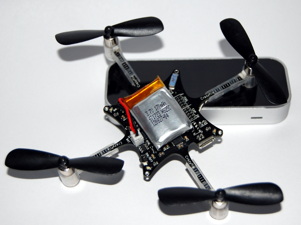
The past weekend marks the two year anniversary of Bitcraze, the company we founded to manufacture and make the Crazyflie Nano Quadcopter kit available. Even though there’s been a lot of hurdles along the way we finally made it all the way to our goal! It’s been a great year with lot’s of fun things happening like finally testing the pre-series, visiting Seeedstudio in Shenzhen, seeing our empty forum filling up with active users and most of all seeing what users are doing with their Crazyflies. Thanks for supporting us!
Our first year with Bitcraze was spent doing lots of development, design, testing and sourcing. This year has been spent on lot’s of planning, administration, support and preparing for a release. We have said this a few times before, but it’s worth saying again: The easy part was getting the Crazyflie to fly, the hard part was manufacturing and releasing it. Having a company, website and production takes a lot of time. We are really happy with our co-operation with Seeedstudio, without them taking care of production/orders/sourcing/etc. we wouldn’t have had any time over for development.
One of the questions we were asking ourselves before Bitcraze was how our development would be affected when we suddenly had users using our hardware and software. Back then we basically did what ever we felt like doing, as long as it took us in the general direction of making things better. The client and firmware would suddenly be incompatible for a couple of weeks. If we needed to modify the hardware we just had 3 Crazyflies to patch. Sometimes we would just get fed up with everything and spend weeks doing other projects or going outside to smell the fresh air and get some sunshine. Having users and manufacturing a product changes things. It’s a great (and oddly bizarre) feeling seeing users assembling and using something that we have designed and worked on for so long. Even though we have spent years working with product development as contractors, we have never really seen or communicated with the end-users before. So in order to make this work we have spent lots of time discussing how to do things. That includes everything from naming conventions and work division, to how to organize the wiki and when to build new releases of our software. We once spent a whole night discussing how to name our products internally (like BC-CFK-04-A). Even though things are better now, there’s still room for lots of improvements.
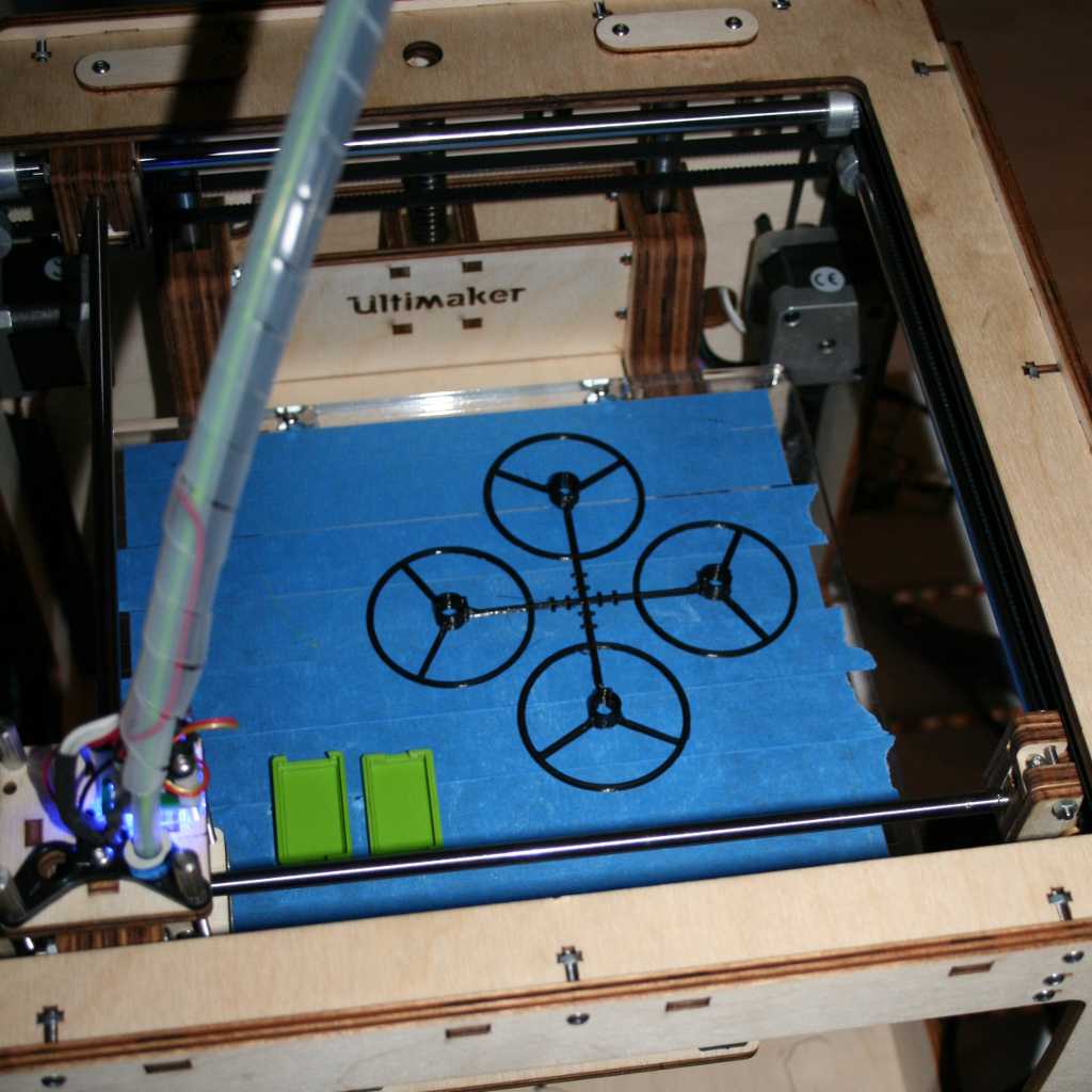
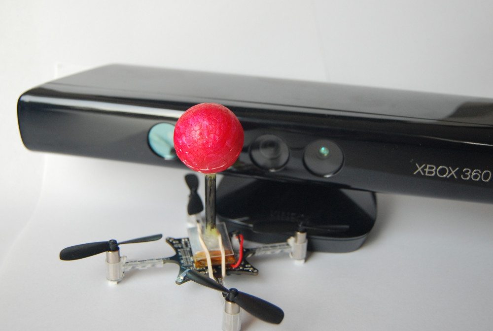
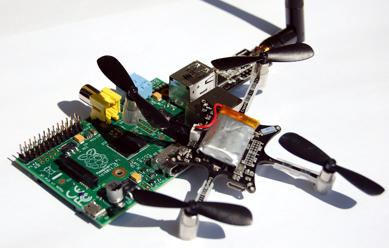
So what’s the plan for the coming year? To get more development done! By now we have done most things for the first time, so hopefully the next time it won’t be as much work. Now that the summer is over and we have cleared our backlog of administrative tasks, we are hoping to get some momentum again. We will also try to find more fun things to do and to broaden the usage of the Crazyflie platform, like the Kinect and Leap Motion work, so that users can keep exploring and developing new things.

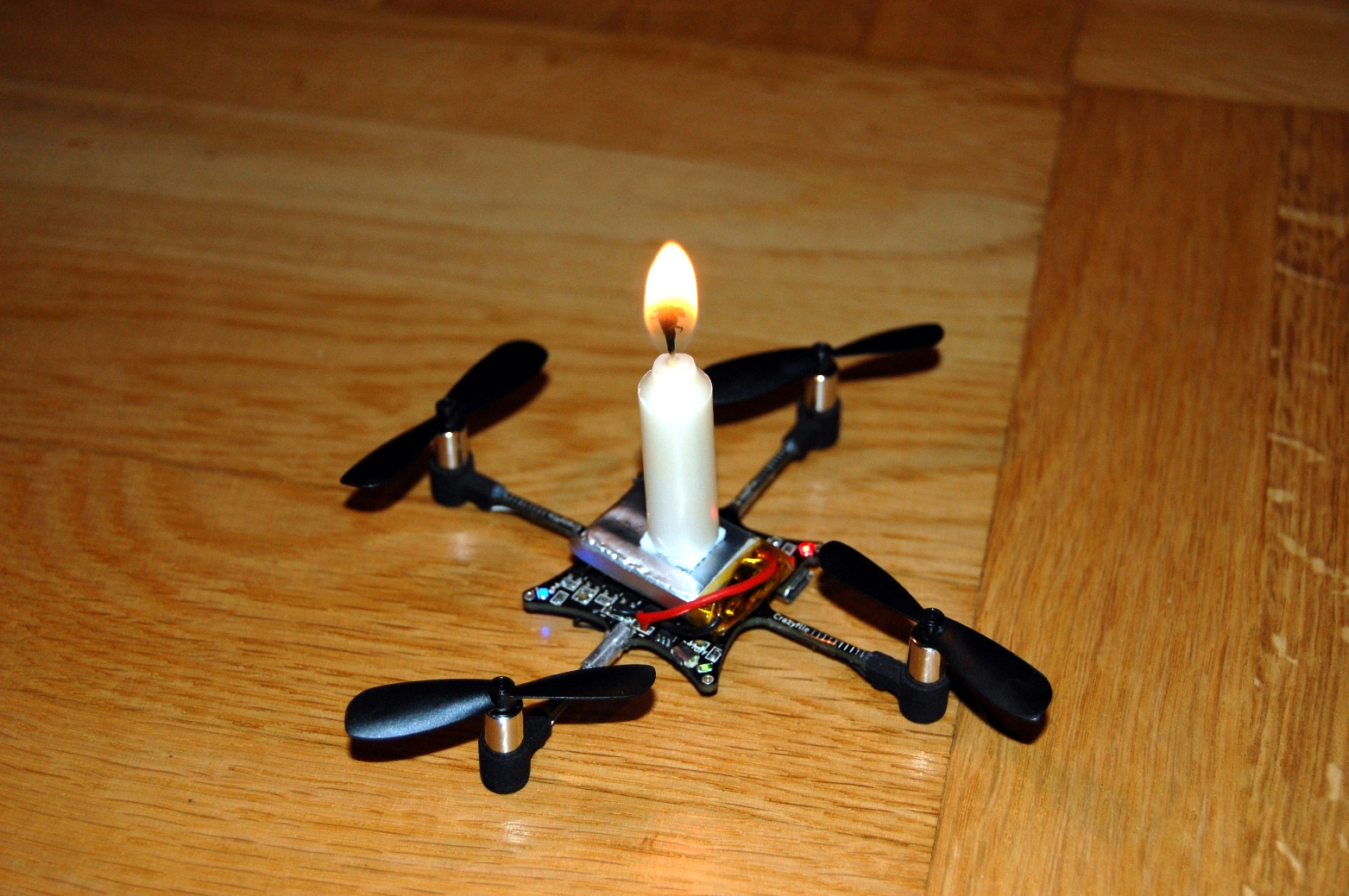
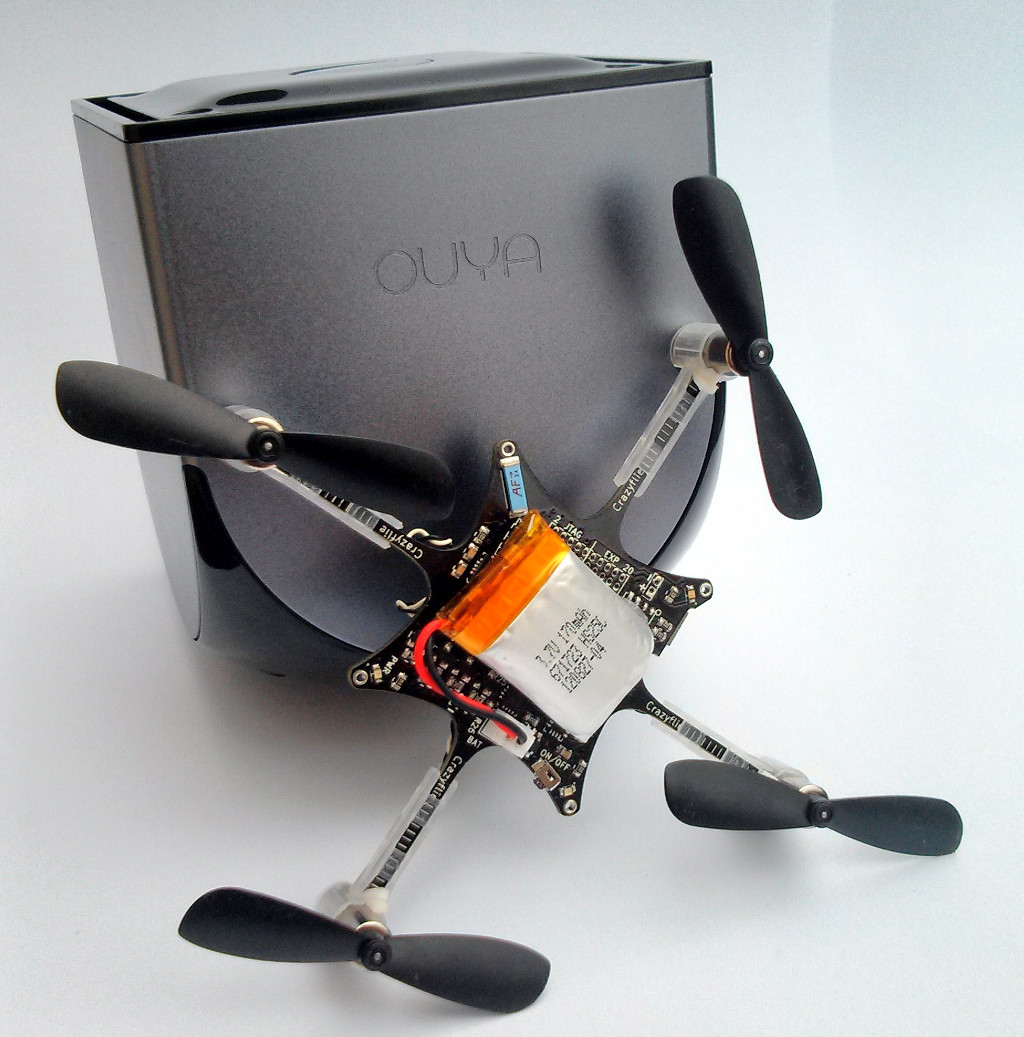
The image is actually the same image we posted last year when Bitcraze turned one. We are now one year older and wiser, which means we know better then to attach a lit candle to a LiPo battery and try to fly the quadcopter :-)