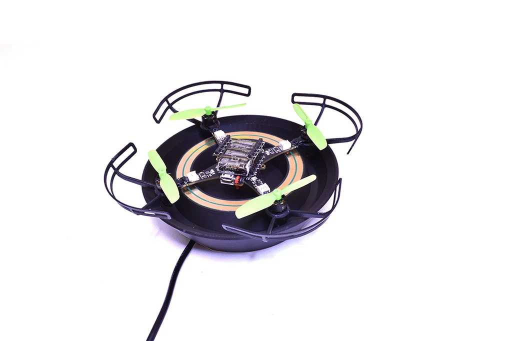
It’s always a good feeling to wrap up the week with a Fun Friday project – especially when it involves some questionable mechanical additions to a Crazyflie platform. This time, I decided to test the capabilities of the upcoming Color LED deck by turning it into a Disco deck.
Mechanics
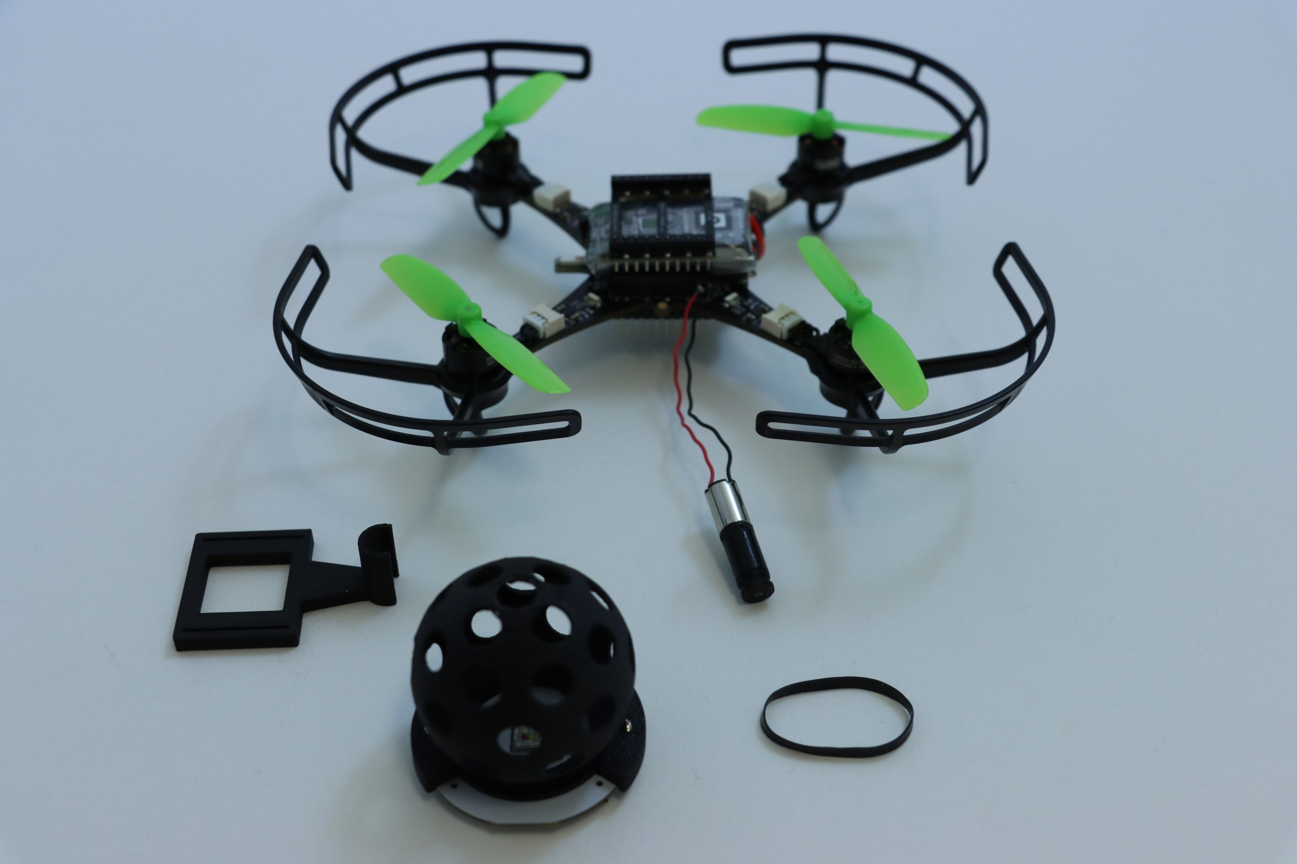
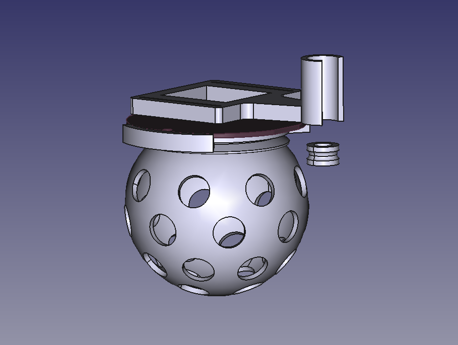
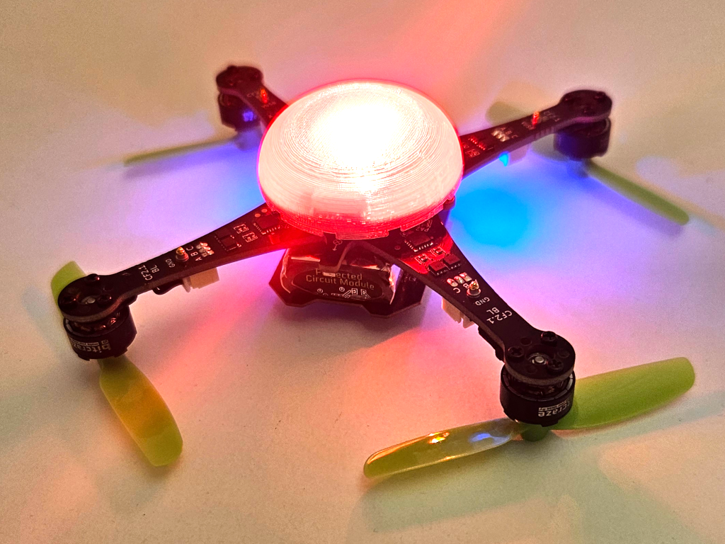
The core of the Disco Deck is pretty simple: a 3D-printed disco ball mounted directly on top of the Color LED Deck with a couple of screws. To bring it to life, I added a Sub-Micro Plastic Planetary Gearmotor and used a rubber band as a drive belt to transfer the rotation. It’s a lightweight, low-tech solution that works surprisingly well with the Crazyflie 2.1 Brushless. All the structural parts were designed to be easily 3D printed in PLA, and they fit on a single print plate for a quick build. You can find all the part files here.
Electronics & Firmware
On my first attempt, I connected the motor directly to VCC and GND, which meant it started spinning as soon as the Crazyflie powered up. This turned out to be a problem as the vibrations prevented the Crazyflie from completing its initialization sequence, since it needs to remain completely still for about one second at startup. The proper fix was to connect the motor to one of the GPIO pins (IO_4) along with GND. For the firmware, I added a new deck driver for setting the IO_4 output to low during initialization and controlling it through a parameter.
Next Steps
The biggest limitation of the current Disco Deck design is the landing. The disco ball extends below the length of the Crazyflie 2.1 Brushless legs, which means the drone can’t take off or land horizontally – not even when using the standard Crazyflie 2.1 Brushless charging dock. To fix this, I’m planning to design a custom charging dock that also works as a stable landing platform for the Party drone.
If you’re interested on the process, you can check out the project repository for any updates.
It’s been a while since our last update on what started as the High powered LED deck prototype. We have finally had time to push this project forward and are aiming to have a release at the beginning of 2026.
A New Name and a Familiar Design
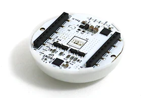
You might notice that the deck has a new name, something simpler and a bit catchier, the Color LED deck (bottom-mounted and top-mounted). The overall design and specs, however, remain very similar to the original concept:
Using a highly efficient high powered LED for maximum brightness
DC/DC driving circuitry for improved efficiency and consistent performance
A light diffuser for smooth, even illumination and wide visibility
Two versions, top or bottom mounted, depending on your build
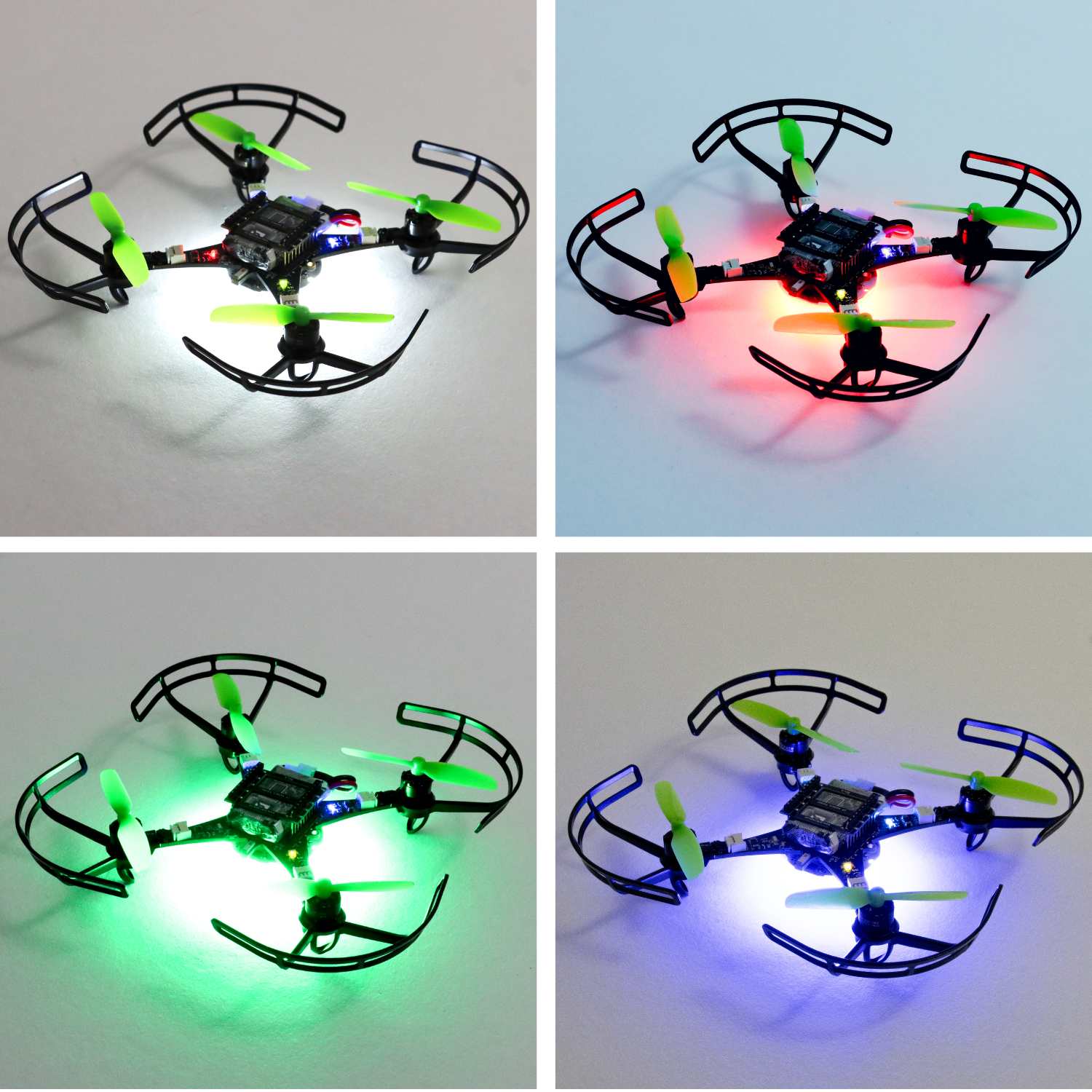
The Color LED Deck brings fully programmable lighting to your Crazyflie, allowing you to create and control custom light patterns in real time. It’s useful for flying in darker environments, for visual tracking experiments, or for adding synchronized light effects in drone choreography. The deck is now also compatible with the Crazyflie 2.1 Brushless, bringing dynamic lighting to our most recent platform for the first time.
Software architecture
This deck will also be the first to use the new DeckCtrl architecture. If you’re curious about how that works, you can read more about it in this earlier blog post.
The Color LED deck has some intelligence built into it that runs on a STM32C0 MCU. The open-source firmware is still under development, and the repository can be found here.
Availability
The final pricing is still being determined, but make sure to sign up for the in-stock notification at the Color LED deck store pages (bottom-mounted and top-mounted) to get an update as soon as it’s available. And as always, keep an eye on the blog for more updates as we get closer to release.
When flying the Crazyflie Brushless, you may have noticed something familiar, as the battery drains, the drone becomes less responsive and can not generate the same amount of thrust it had at the start of the flight. This is because as the state of charge drops, the battery voltage decreases, and that directly affects the thrust output of the motors.
We wanted to fix this. In this post, we’ll explain why the old compensation method wasn’t ideal, how we used system identification to design a new battery compensation scheme, and how this improves thrust consistency across the entire battery range.
Motivation
The key problem is simple: a dropping battery voltage means a dropping thrust for the same command. This leads to flights that start crisp and responsive but is reduced as the battery drain.
Our goal was to make sure that, regardless of the state of charge, the actual thrust stays close to the commanded thrust. Though, for manual flight, sometimes this might not be preferred, so there will be an option to turn it off.
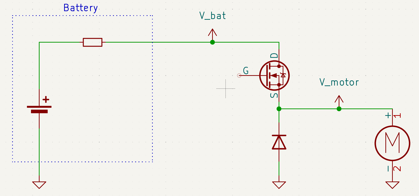
To illustrate the setup, here is a schematic of how the battery, PWM switching, and motor interact, effectively behaving like a simple buck converter:
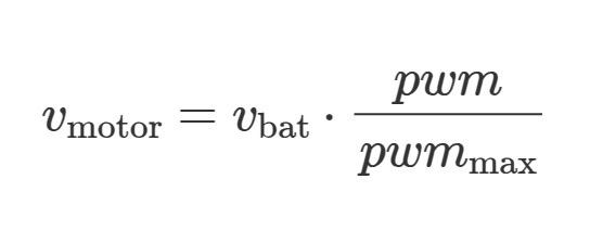
This means the motor voltage can be computed by:
System Identification
To design a proper compensation, we first needed to understand how thrust relates to motor voltage. This meant running a series of experiments on the thrust stand introduced in this earlier blog post.
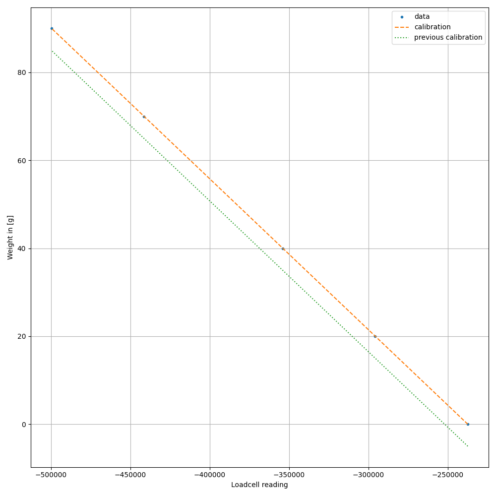
The first step was calibrating the loadcell used to measure thrust:
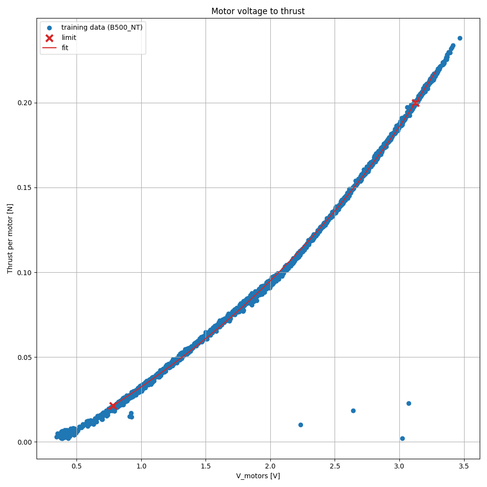
Once calibrated, we measured the thrust at different applied motor voltages.
As expected, the thrust can be modeled well by a third-order polynomial in motor voltage.
Mathematically, the relationship comes from two simple facts:
A DC motor torque is proportional to motor voltage and inversely related to motor speed.
A propeller’s thrust scales approximately with the square of the rotational speed.
Combining these effects leads to a nonlinear (third-order) relation between motor voltage and thrust.
Battery Compensation
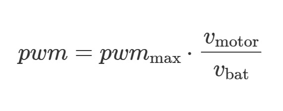
The main idea is straightforward: instead of assuming the battery voltage is constant, we explicitly account for it. We can measure the battery voltage and low-pass filter it to reduce noise. Together with the necessary motor voltage from the curve above, we can solve the equation from above for the necessary pwm to apply:
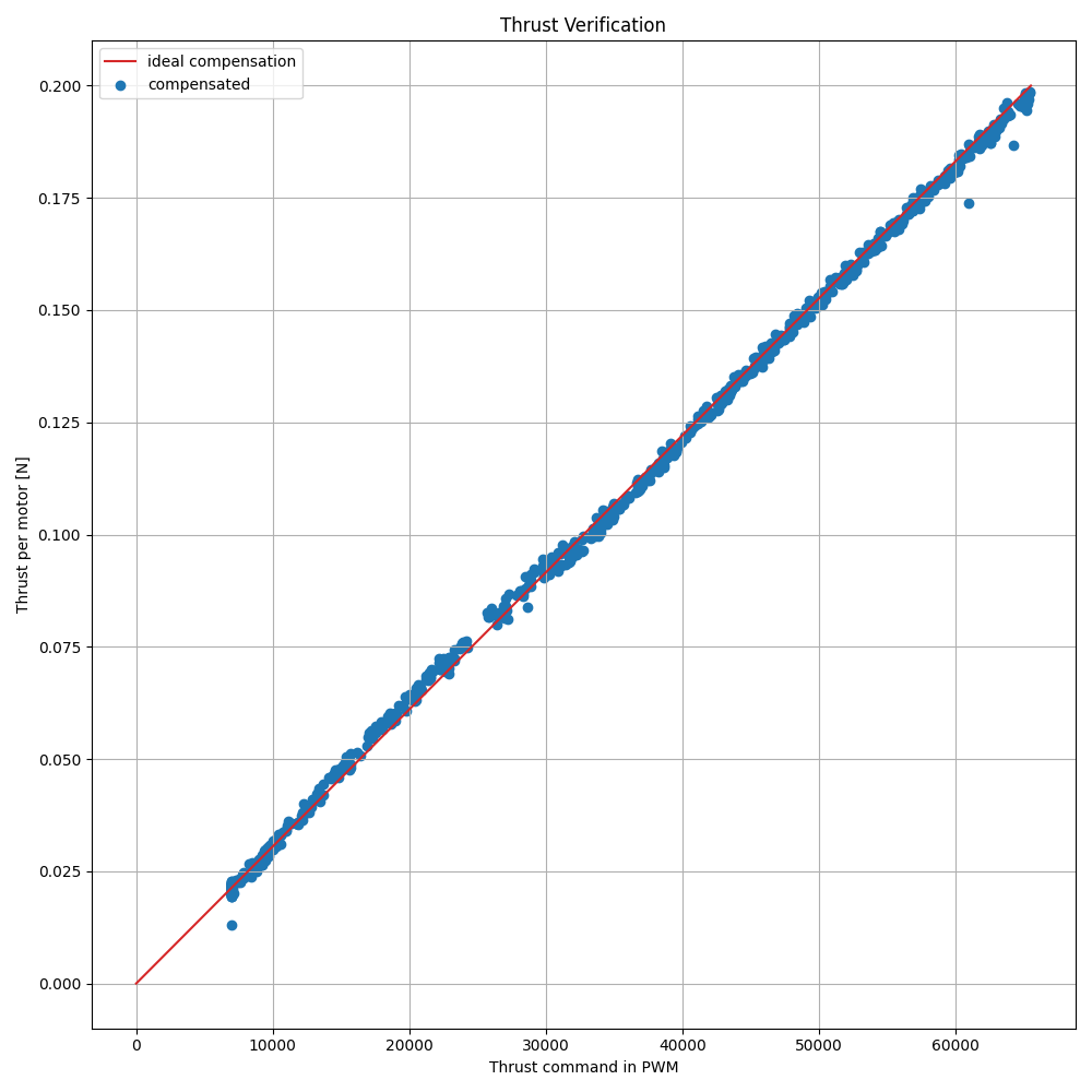
This corrected motor voltage is then fed into our third-order model to compensate the thrust command. With this compensation, the commanded-to-actual thrust relation is now approximately linear, which is exactly what we want. We can verify this by applying thrust commands and comparing them to the actual thrust.
Dynamic Behavior
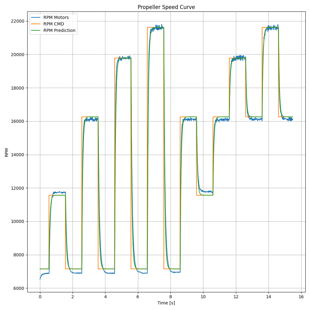
To obtain a complete parameter set of the motors and propellers, we also performed dynamic tests: commanding rapid increases and decreases in PWM and measuring the thrust response.
These dynamics are not required for the battery compensation itself, but they are very useful for accurate system identification and for simulation purposes.
Discussion and Conclusion
The new compensation method (#PR1526), ensures that thrust is consistent across the full range of battery charge. Compared to the old approach, it is both simpler to understand and more faithful to the actual physics of the motor–propeller system. The result is flights that feel the same at the end of the battery as at the beginning.
Beyond just improving flight performance, the system identification work also provides us with a full parameter set for the Crazyflie. We are already using these parameters in Crazyflow, our new simulation tool that models the Crazyflie dynamics with high fidelity. If you’re interested in simulation or in testing new control strategies virtually, check it out!
We’re excited to hear feedback from the community and to see what you do with this new capability.
One of the unique characteristic of the Crazyflie platform is the fact that decks (the Crazyflie expansion boards) are detected dynamically at startup. This makes the platform pretty much plug and play: plug a flow deck and you can fly autonomously with relative positioning, no configuration or recompilation required.
In this blog post we will present a new system we have implemented to identify and enumerate decks. This is intended to be the new default from now-on and can be used by anyone who wants to make a Crazyflie-compatible deck.
Current system: 1-Wire Memories
This is currently achieved using 1-Wire Memories. These memories can be discovered and addressed using a guaranteed unique serial number. This means that there can be as many memories as we want on the bus and they can all be discovered and read.
In the Crazyflie ecosystem, every deck has a 1-Wire memory that contains the identity of the deck. At startup, the Crazyflie discover and read all the memories which allows to discover all the decks and initialize the corresponding deck driver.
The future: DeckCtrl
The current system works very well but is has two major shortcommings:
The 1-Wire memory we are using does not provides GPIO or any other control. It makes it impossible to control the deck “out-of-band” in order to switch it on/off or launch a bootloader for example.
The 1-Wire memory has only one manufacturer and, because of a lot of reasons, we can only use a single model of it. At times it has caused us stress when the chip availability is low.
The new DeckCtrl-based system addresses these two problems by using a regular micro controller over I2C and provides support for GPIO as well as, in the future, UART, SPI and any other protocol that might be needed to handle the deck startup and configuration.
DeckCtrl is mainly a protocol definition. The current implementation is for STM32C011 micro controllers. While this could be implemented on any micro controllers, we will likely stick to the STM32C011 for the foreseeable future.
Deck discovery over I2C
One of the main innovations is the development of a new discovery and enumeration algorithm over I2C. Indeed, one of the main difference between I2C and 1-Wire is that 1-Wire memories are addressed using a 64Bit unique serial number while I2C uses 7 (or 10) bit addresses. This means that it is impractical to assign a unique I2C address to each device, and even if we tried to assign one address per deck type it would make it impossible to detect the same deck multiple times on a Crazyflie.
To solve that problem we designed a protocol that allows starting all DeckCtrl on the same address and enumerate them so that we can select all of them one by one, and then assign them a unique address on the bus. At a high-level this behaves very similarly to DHCP, where all devices will be assigned an address dynamically.
Once the decks have all been configured, it is possible read a memory to recover the deck identity and initialize deck drivers as we are currently doing.
Just that is a great step forward for Bitcraze: we are not dependent anymore to a single model of 1-Wire memory.
Deck life-cycle control
The second major improvement is what I called earlier “out-of-band” control of the deck. By that I mean that we can have control over the deck that is independent from the deck’s main micro controller chip. This is something we have long missed to, for example, be able to put decks in bootloader mode. The solution that has been used for the lighthouse deck is to always start in bootloader mode and then boot. This works, but has proven to be impractical for some use-cases and is not possible with all micro controllers.
The new DeckCtrl protocol defines space for GPIO control and the possibility for more in the future. This allows for example to switch ON and OFF a deck in software if one of the GPIO is used to control the deck power supply. We can also control the Reset and Boot pin of a micro controller in order to put it in bootloader mode.
Our goal there is to greatly simplify the design of more clever decks based on micro controllers. This will allow us, and anyone interested in making decks, to make more competent decks while making is easy to develop the firmware for them. For example, we will be looking at allowing to reprogram decks without having to restart the Crazyflie, which will make it much easier to develop and iterate.
Status
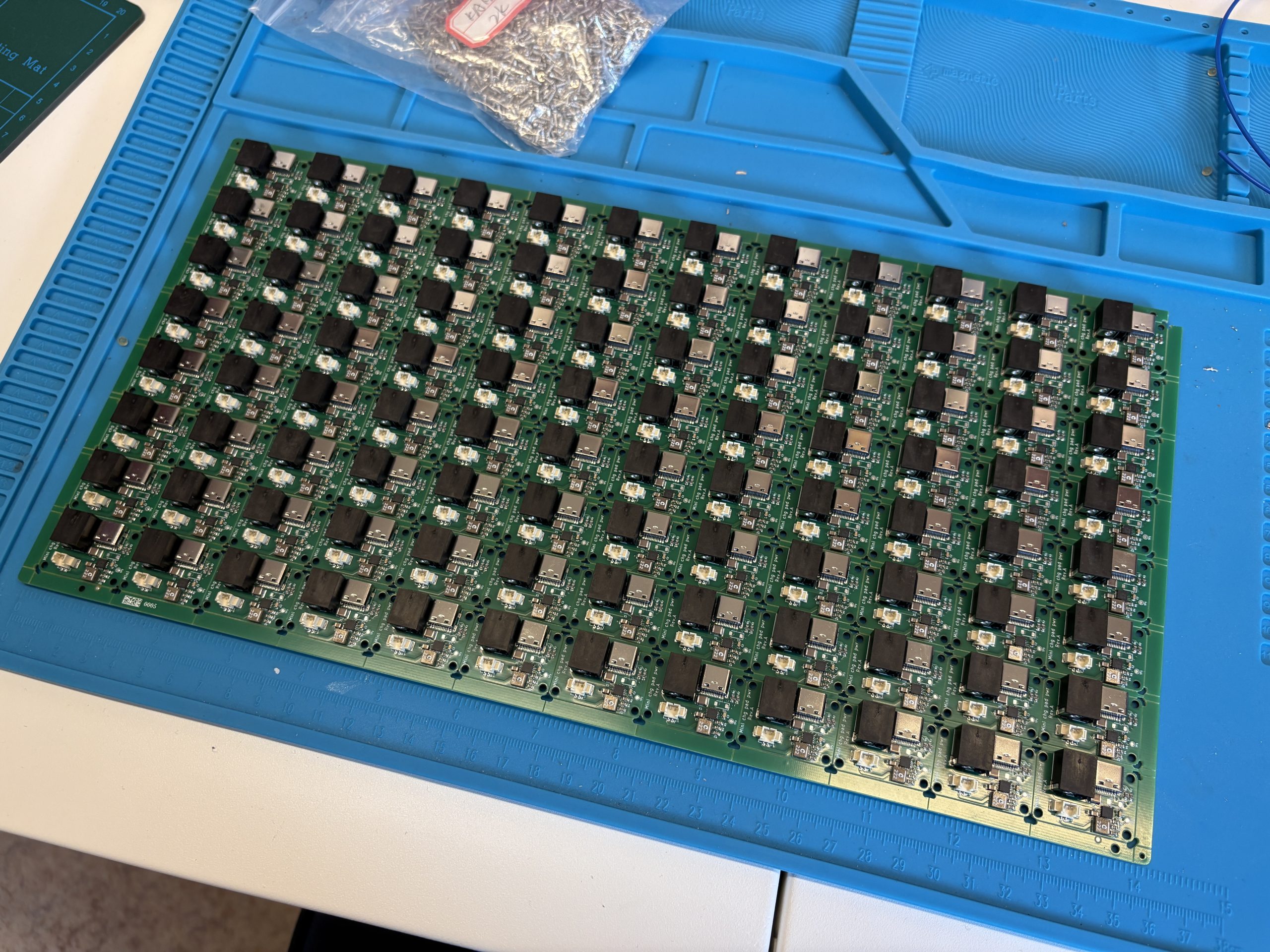
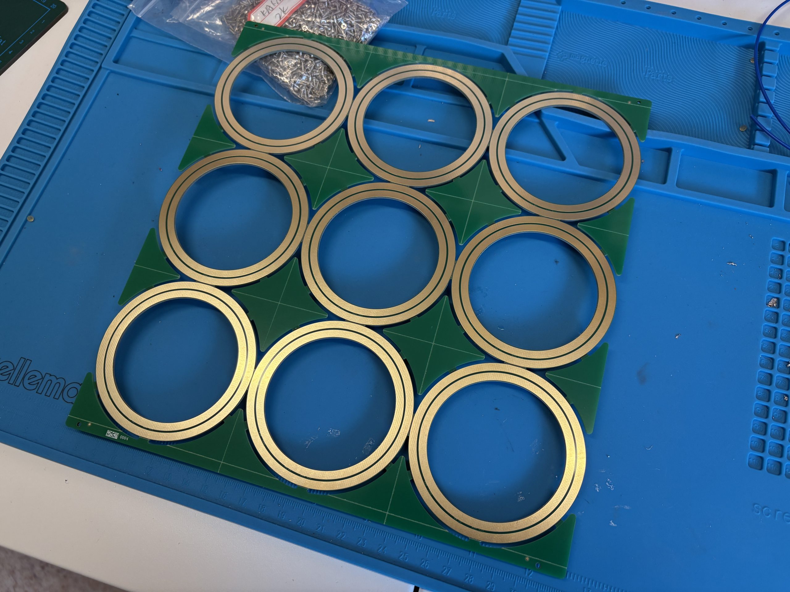
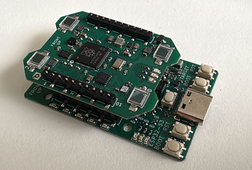
We have now finished the first iteration of the DeckCtrl protocol design and implementation. There is also a driver that exercises the GPIO part of it, this has been tested to work on many identical decks at the same time on a dev-deck we use for development:
This has been done in the context of the High-Power LED deck project. This future deck will feature a powerful RGBW LED which will be controlled by a micro controller onboard the deck. So it will be seen as an I2C device from the Crazyflie side. This design also shows the intent of DeckCtrl as this deck has 2 STM32C011: one implementing DeckCtrl and one application micro controller implementing the LED driver and other useful functionalities like color correction and temperature monitoring.
At the beginning of the year, we released the Crazyflie 2.1 Brushless charging dock. This project was very much an experiment for us since this is the first product we are mainly manufacturing and assembling by ourselves in Sweden. We though we would write a little bit about the reason we made it that way and how it is going.
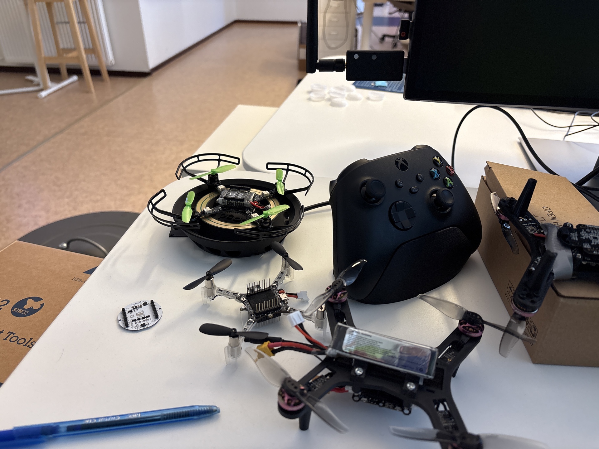
The Chaging dock is already described in a brunch of peviousblock post. It is basically a landing pad for the Crazyflie Brushless that charges the Crazyflie when landed. This is an idea and a design we have been using for years for our fair demos and that has been very useful, we would not be able to continuously fly at fair without it! Some of us even started using is on their desk to keep their Crazyflie Brushless fully charged at all time while developing with it:
However, even though it has been so useful for us, and we designed the Crazyflie Brushless to be compatible with contact-charging, we where not sure of how many people out there would want or need such a charging dock. So we decided to make it available in an experimental manner by manufacturing it by ourselves!
Why ‘made in Malmö’?
While the manufacturing we have in place for all our other products works really well, it requires a non-trivial amount of effort to start the first manufacturing batch. This is mainly due to the fact that the full mass production chain needs to be setup for the first batch and that production happens outside Bitcraze, this requires a lot of work in documentation, planning and administration.
However by doing the production in house, we are able to fix issues as they arises and to work in a much more agile way. In house production will of course no scale, but for a proof of concept it might work, this is at least what we wanted to experiment with.
There are two main improvements that has allowed us to even consider in-house experimental production: the advent of cheap and efficient PCBA services and the improvement in 3D printers reliability. This allows us to source all the parts and assemble them to make the final product.
How is a Charging Dock made?
The charging dock is comprised of two main parts: the plastic landing pad and the electronic.
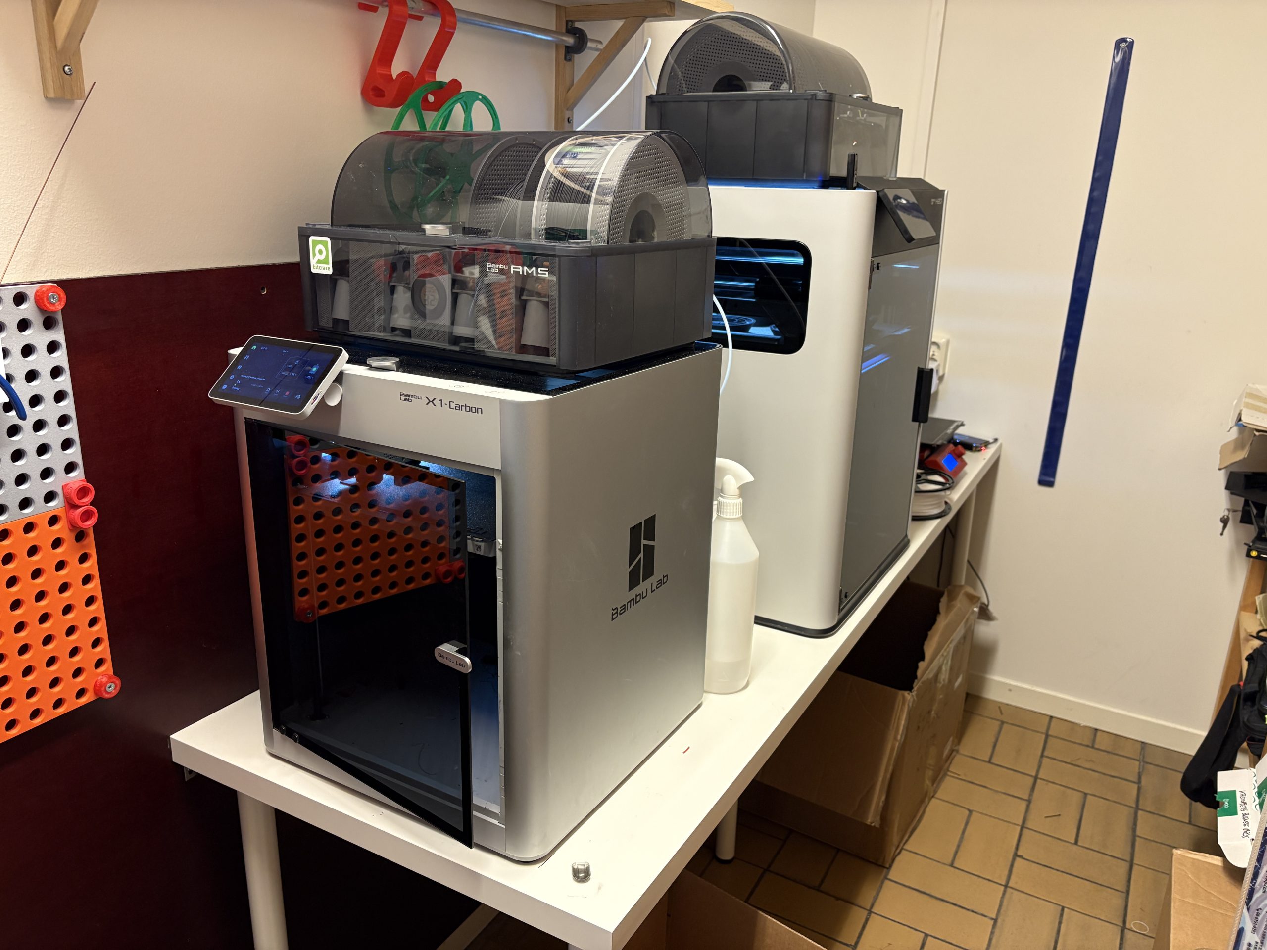
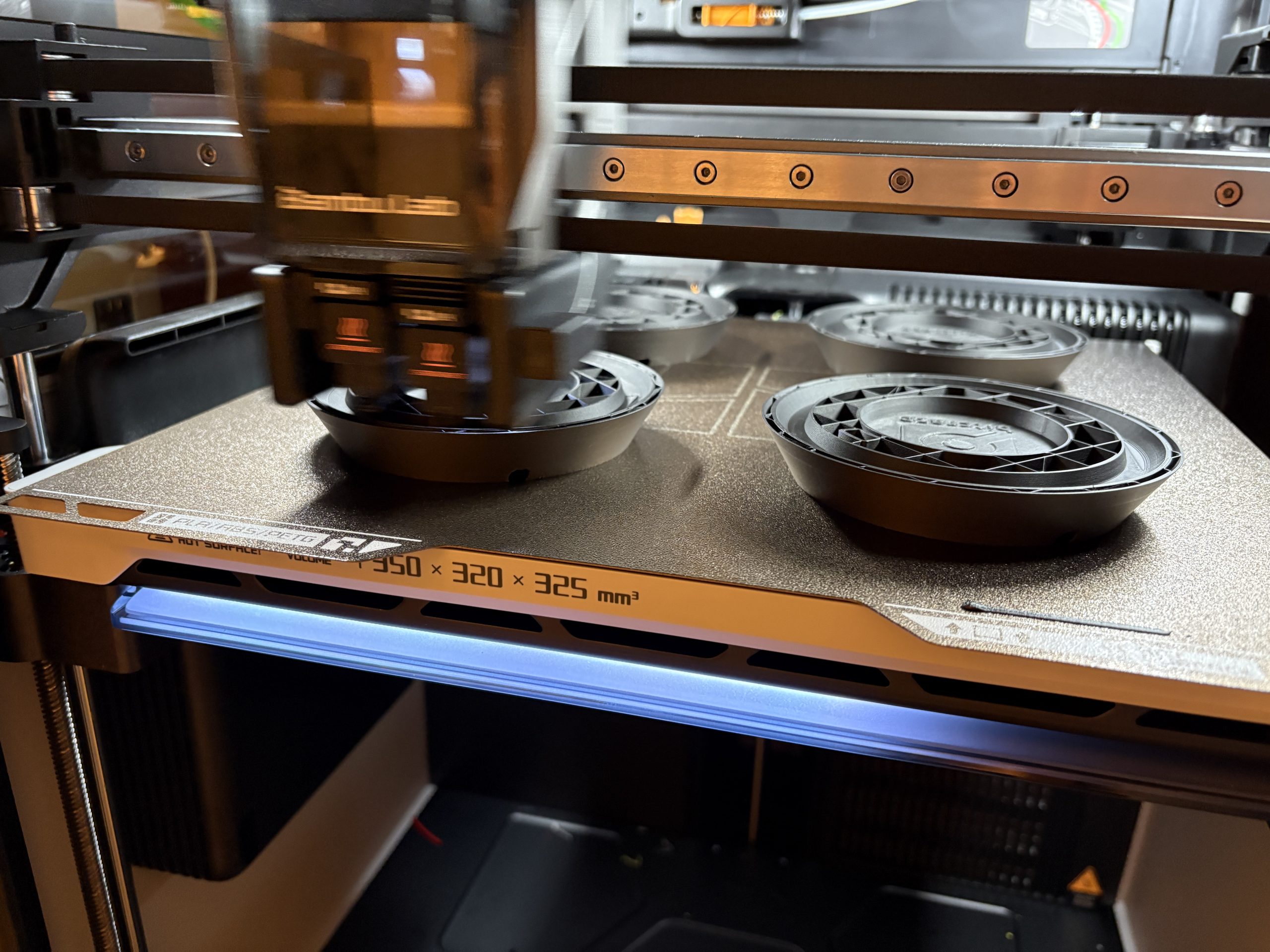
The Landing pad is 3D printed by us. We now have a mini-print-farm at the office (if a Swarm starts at 2 drones, a print farm shall start at 2 concurrently running printer :):
What made it possible for us to consider running this kind of production was when we got our Bambulab X1 carbon. It is much more reliable and most importantly easier to maintain that any printer we got before, which gave confidence that we could start making products of what we printed. We now have an H2D as well. This currently allows us to print 12 landing docks per working day.
On the electronic side, we are now able to order fully assembled PCB, and even custom cable within weeks.
All we then need is assembly and testing and we got ourselves a small production line with very little risk and a lot of flexibility.
What now?
We are very pleased with what we have achieved so far with the charging dock. The first batch is sold out and we have started manufacturing a new batch with no big pain-point in sight. At some point we will have some decision to take though: do we continue in house or transition to more traditional manufacturing? Will all the work we put so far be useful for setting up mass manufacturing or will we have to restart from zero? At what batch size or frequency will we need to transition?
However this is also one of the great advantage of this: we have full control and we can decide when to manufacture where. As we have talked a bit previously, Bitcraze is a self-organized company, and this experiment actually fits very well with our way of working and keeps us agile. We hope this can free us from the doubts we usually have when thinking about more ‘niche’ products and will allow us to try new things in the future.
Today’s blogpost comes from Joseph La Delfa, who is currently doing his Industrial Post-Doc with Bitcraze.
The Qi deck and the Brushless charging dock allow you to start charging a Crazyflie quickly, without having to fiddle with a plug or a battery change. But when you need to charge 10 or more Crazyflies 2.x and don’t want the weight penalty of the Qi deck then some some other solutions are needed.
This blog post is about a couple of chargers I made for the Crazyflie 2.x for my research prototypes. I research interaction design, which often means building something new and then putting in the hands of a user and getting them to try it out. What is important in these scenarios is that when there is unexpected behavior, they don’t think that the prototype is bugging out or broken. One way to prevent this is to make things that have a higher quality to raise the expectations of the user. This can help them stay immersed in the interaction and not look over to me when there is unexpected behavior and say… “is this working properly?”
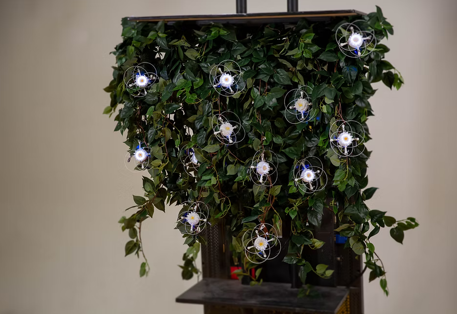
Wiring Harness for Drone Chi
This charger is essentially a pair of JST 2-pin extensions for a 1S battery charger that I soldered together. Then weaved them through some fake hanging plants. With the drones already looking like flowers for the Drone Chi project, they blended well into the fake plants and all the wires were well hidden. When you wanted to fly, you would disconnect the battery from the wiring harness. Plus it brings the nice experience of picking a flower from a bush before you start flying!
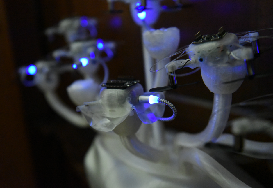
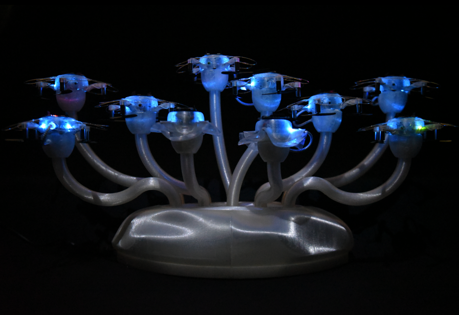
Magnetic Mantle Piece Charger for How To Train Your Drone
This charger allows 10 Crazyflies to charge from their USB ports, but on a bit of a statement piece charger that lived in the lounge room of a group of friends who were participating in a month-long user study during the How to Train Your Drone Project. This charger contained a powered USB hub with cables running through each of the medusa like tubes rising from the base. What made this charger special was the magnetic USB charging adapters (available widely on e-bay, amazon, temu etc) that were plugged into the the USB ports on the drone. These allowed you to securely place the drone on the charger in one action as the magnetic cables integrated into the charger were always close enough to the drone when you set it down, giving you a satisfying * click * every time! They also gave off a eerie blue glow which I think matched the Crazyflie well.
At Bitcraze we like making decks! When we released the Crazyflie 2.0 we were really excited about the new deck connector we put on the platform. Using this, it was suddenly possible to expand the platform, adding new, more complex functionalities years after the initial release. It’s something that we really like about the Crazyflie. Over the years we’ve released a bunch of decks and also updated a few of them as new, improved sensors became available.
Deck limitations
As the number of decks has increased, along with their complexity, we’ve started noticing some limitations. We’ve touched on this a while back in this blog post where you can find more details, but here’s a short summary:
Resource sharing in the STM32F4: Mainly DMA conflicts between different peripherals, like conflict for DMA using DSHOT on the Crazyflie 2.1 Brushless and the WS2812b driver for the LED-ring.
Bus arbitration and performance: Some decks make excessive use of some buses, which can cause issues with certain combinations like the LPS deck and micro-SD card deck.
Deck combinations and pins: As more interesting decks are released and we’re able to carry more weight, users want to combine more decks. Although we try to be smart with pin allocation there’s a limit on how you can combine the decks.
MCUs on decks: As the complexity increases, separate MCUs are also included on the decks. Although working well for offloading the main MCUs on the Crazyflie, the complexity quickly increases both for usage and for development. This is something we’ve seen with the AI deck for instance, which contains 2 MCUs.
Like suggested in the original blog post, the solution will be to move more intelligence onto the decks by putting MCUs on them. These MCUs can then use the hardware on the decks without sharing resources with the main Crazyflie MCU and can also help process the data to make the communication with the Crazyflie more high level. But doing this will of course then make the issue raised in the last point even worse. To mitigate this we need to have better control over the decks. Our proposed solution for this is adding a new MCU to the decks which acts as a controller. Being able to switch on/off power, bootstrap and control various aspects of the deck. Some of the features include:
Uniquely identify the deck and also identify the model of deck – This will replace the current 1-wire memory subsystem we have today
Uses minimal amount of pins, basically only using the I2C pins
Use the MCU pins as GPIOs or as various peripherals:
GPIO expander enables switching on/off onboard power supply, simplifying bootloading and saving power. It also enables bootstrapping of onboard MCUs, which can be used for selecting what output pins to use for various functionality
Bridge I2C to SPI/UART for bootloading of onboard MCU. This would of course be much slower than using the SPI/UART but would simplify bootloading and not need pins allocated on the expansion connector
Bootstrapping the board makes it possible to to implement support for duplicate decks, for instance selecting what UART (1 or 2) on startup makes it possible for the driver on the Crazyflie to start up each deck and select what UART is used.
Our implementation
For our implementation of this system we have selected the STM32C011 MCU, as it comes in various packages from very small to slightly larger, so it’s possible to solder by hand. It also has the features we needed. To maximize the the flexibility of the system we don’t want to program in the I2C addresses in production. Even if you disregard the fact that the address might conflict with other I2C devices in the future, it will definitely conflict if you add two of the same type of deck.
To fix this we will automatically detect all the deck-ctrl MCUs on the bus and then move them to individual addresses. This will enable us to change the addresses in the future if there are collisions and also allows multiple instances of the same deck attached at the same time. Below is a video demonstrating this in action, implemented on custom development decks we’ve made for simplifying firmware development. Each deck runs the same deck-ctrl firmware and all 3 are auto-detected at startup.
The future
The current solution will be used on our next two upcoming decks: the new LED deck and the new Lighthouse deck. As we get closer to their release we will publish the firmware for the deck-ctrl MCU on GitHub. If the design turns out well we will keep rolling it out to future decks, increasing the flexibility of the deck expansion system even more.
The ability to attach expansion decks to the Crazyflie platforms without modifying their electronics allows experimenting with different hardware components. Most existing decks contain different types of sensors that are used for positioning and collecting data. On this Fun Friday project that has been running for the past couple of months, I explored adding mechanical principles to the Crazyflie with the long-term goal to create a working claw to grab and transfer objects.
The claw
The claw mechanism is built on a DC motor. The motor shaft is connected to a worm gear, which drives the claw to open or close depending on the direction of rotation. All the parts are 3D printed and designed from scratch.
The deck
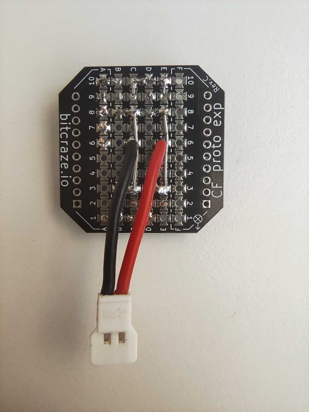
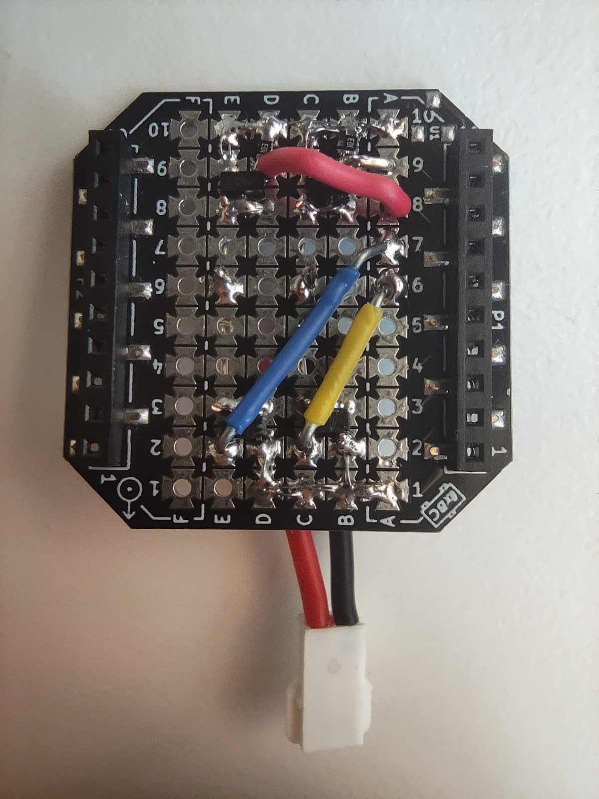
Making the DC motor rotate in both directions requires reversing its polarity, which can be done using an H-bridge. So, the deck controlling the claw, is essentially an H-bridge that uses VCC 3V, GND and 4 GPIO pins on the Crazyflie. This way it can be compatible with the Lighthouse positioning deck. The circuit consists of 4 Mosfets (2 P-type and 2 N-type) and 2 pull-down resistors.
How it works
When designing a custom deck for the Crazyflie, you need to initialize it with its own drivers. The drivers for the H-bridge deck contain 2 basic functions; the one that opens the claw and the one that closes it. They are triggered using 2 float parameters (clawOpen and clawClose), and remain active for the number of milliseconds specified by the value of each parameter.
Experiments
Since the entire claw setup weighs 29g, I used 2 Crazyflie 2.1 Brushless drones, to equally share the weight, while one of them controls the claw. Together, they can lift up to 74g. A fishing line is attached underneath each drone and the claw can slide along it, keeping it always centered between them. For the load, I used a Crazyflie 2.1+ with a lighthouse deck attached and its motors removed, to reduce its weight. When the script starts, the initial positions are collected and a flight sequence for the swarm is created based on them. Then, the swarm takes off and approaches, grabs, lifts and transfers the load.
Next steps
The initial goal of grasping and transferring objects with a flying claw has been achieved. However, in the future I plan to make the system more robust and easy to use. Some points that I might focus on:
Making the whole setup lighter – replace the current motor with a lighter one, print with lighter materials.
Improve the controller tuning to damp the oscillations and make the flight more stable.
Implement a control system to keep track of the claw’s state – add limit switches.
As some of you may have noticed, the current LED-ring deck doesn’t play nice with the Crazyflie 2.1 Brushless. The culprit? A resource clash between the DSHOT motor signals and the WS2812 LED driver used for the LED-ring.
But good news! We’re prototyping a new LED deck that solves the conflict by switching to I2C communication. Not only does this fix the compatibility issue, it also gives us a chance to improve its features. Here’s what we’ve improved so far:
Using a highly efficient high powered LED
DC/DC driving circuitry to improve LED driving efficiency
1W on each channel (red, green, blue, white)
LEDs on both sides so it can be mounted both on top or on bottom of the Crazyflie
LED-deck with a 3D-printed diffuser mounted underneath the Crazyflie 2.1 brushless
The LED we’re using is very powerful and the light is emitted from a small area, so a light diffuser is needed to get a more pleasant light. Designing something that can be manufactured is the next step of the project. Make sure to follow our blog to get more updates on this project.
There has been some extended work lately related to the Lighthouse positioning system. The goal of this work is to expand the maximum base station number to 16 enabling the system to cover larger areas and support more complex use cases.
Previous work
One previous attempt to enable multiple base stations using the current lighthouse deck left us with a highly untested “hacky” solution. After flashing the Crazyflie with the proper firmware, this solution requires to strategically position the base stations so that no more than 4 are visible at any given time. Then, the geometry estimation that is normally carried out by the cfclient has to be done through the multi_bs_geometry_estimation.py script in the cflib.
Last year we developed a prototype deck, used in last year’s holiday video, that had a bigger FPGA to receive the lighthouse signals and an esp32 to be able to decode and filter most of the lighthouse pulses onboard the deck. This approach ended up not working for us since it still included the moderately-hard-to-develop FPGA and the algorithm we implemented in the esp32 to identify lighthouse V2 pulses happened to be not fast enough to handle enough base stations.
Current limitations
A key factor that currently limits the maximum number of usable base stations is the Lighthouse deck which can’t handle more than 4 visible base stations at a time. Additionally, the Crazyflie’s STM32 is doing all the filtering and 16 base stations generate so much data that it would exceed the compute and memory budget we have in the Crazyflie. This was one of the main reasons to add a MCU in the deck of our last-year prototype.
Ongoing progress
The last couple of months we have redesigned a new LH-16 deck containing a RP2350 microcontroller so that part of the computation and filtering can take place on the deck, rather than on the Crazyflie. With a deck like this, it should be possible to receive large amounts of data from the base stations and filter some of it out to finally estimate the Crazyflie’s position in the Crazyflie’s STM32.
This deck has been designed to run a firmware developed by Said Alvarado-Marin from the AIO team at Inria in Paris. This firmware is able to acquire, decode and identify the FM1-encoded LFSR data stream we get from the base stations without the help of an FPGA or a big look-up table. This allows to greatly simplify the hardware and software by using only one microcontroller on the deck.
We are currently bringing-up the prototype and hope to be able to soon fly in our lab with 16 base stations. We will also be looking at making a standalone lighthouse receiver for other robots and applications. For the curious: the board under the deck in the picture in a debug board that contains everything we might need for making a standalone receiver plus everything needed to bring-up and debug the deck until we have it ready to fly.