As some of you may have noticed, the current LED-ring deck doesn’t play nice with the Crazyflie 2.1 Brushless. The culprit? A resource clash between the DSHOT motor signals and the WS2812 LED driver used for the LED-ring.
But good news! We’re prototyping a new LED deck that solves the conflict by switching to I2C communication. Not only does this fix the compatibility issue, it also gives us a chance to improve its features. Here’s what we’ve improved so far:
Using a highly efficient high powered LED
DC/DC driving circuitry to improve LED driving efficiency
1W on each channel (red, green, blue, white)
LEDs on both sides so it can be mounted both on top or on bottom of the Crazyflie
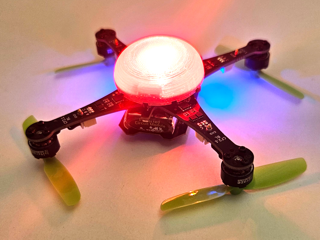
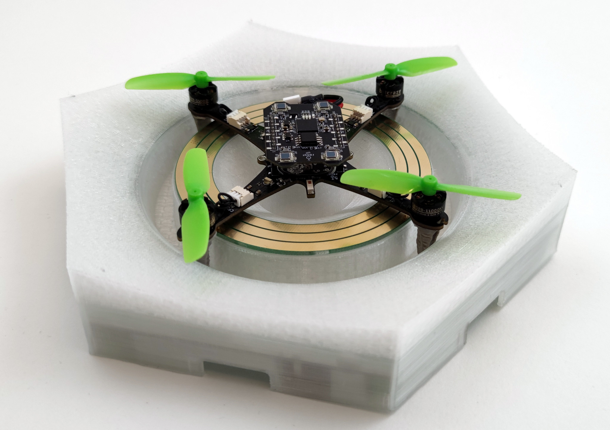
LED-deck with a 3D-printed diffuser mounted underneath the Crazyflie 2.1 brushless
The LED we’re using is very powerful and the light is emitted from a small area, so a light diffuser is needed to get a more pleasant light. Designing something that can be manufactured is the next step of the project. Make sure to follow our blog to get more updates on this project.
There has been some extended work lately related to the Lighthouse positioning system. The goal of this work is to expand the maximum base station number to 16 enabling the system to cover larger areas and support more complex use cases.
Previous work
One previous attempt to enable multiple base stations using the current lighthouse deck left us with a highly untested “hacky” solution. After flashing the Crazyflie with the proper firmware, this solution requires to strategically position the base stations so that no more than 4 are visible at any given time. Then, the geometry estimation that is normally carried out by the cfclient has to be done through the multi_bs_geometry_estimation.py script in the cflib.
Last year we developed a prototype deck, used in last year’s holiday video, that had a bigger FPGA to receive the lighthouse signals and an esp32 to be able to decode and filter most of the lighthouse pulses onboard the deck. This approach ended up not working for us since it still included the moderately-hard-to-develop FPGA and the algorithm we implemented in the esp32 to identify lighthouse V2 pulses happened to be not fast enough to handle enough base stations.
Current limitations
A key factor that currently limits the maximum number of usable base stations is the Lighthouse deck which can’t handle more than 4 visible base stations at a time. Additionally, the Crazyflie’s STM32 is doing all the filtering and 16 base stations generate so much data that it would exceed the compute and memory budget we have in the Crazyflie. This was one of the main reasons to add a MCU in the deck of our last-year prototype.
Ongoing progress
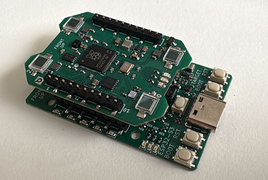
The last couple of months we have redesigned a new LH-16 deck containing a RP2350 microcontroller so that part of the computation and filtering can take place on the deck, rather than on the Crazyflie. With a deck like this, it should be possible to receive large amounts of data from the base stations and filter some of it out to finally estimate the Crazyflie’s position in the Crazyflie’s STM32.
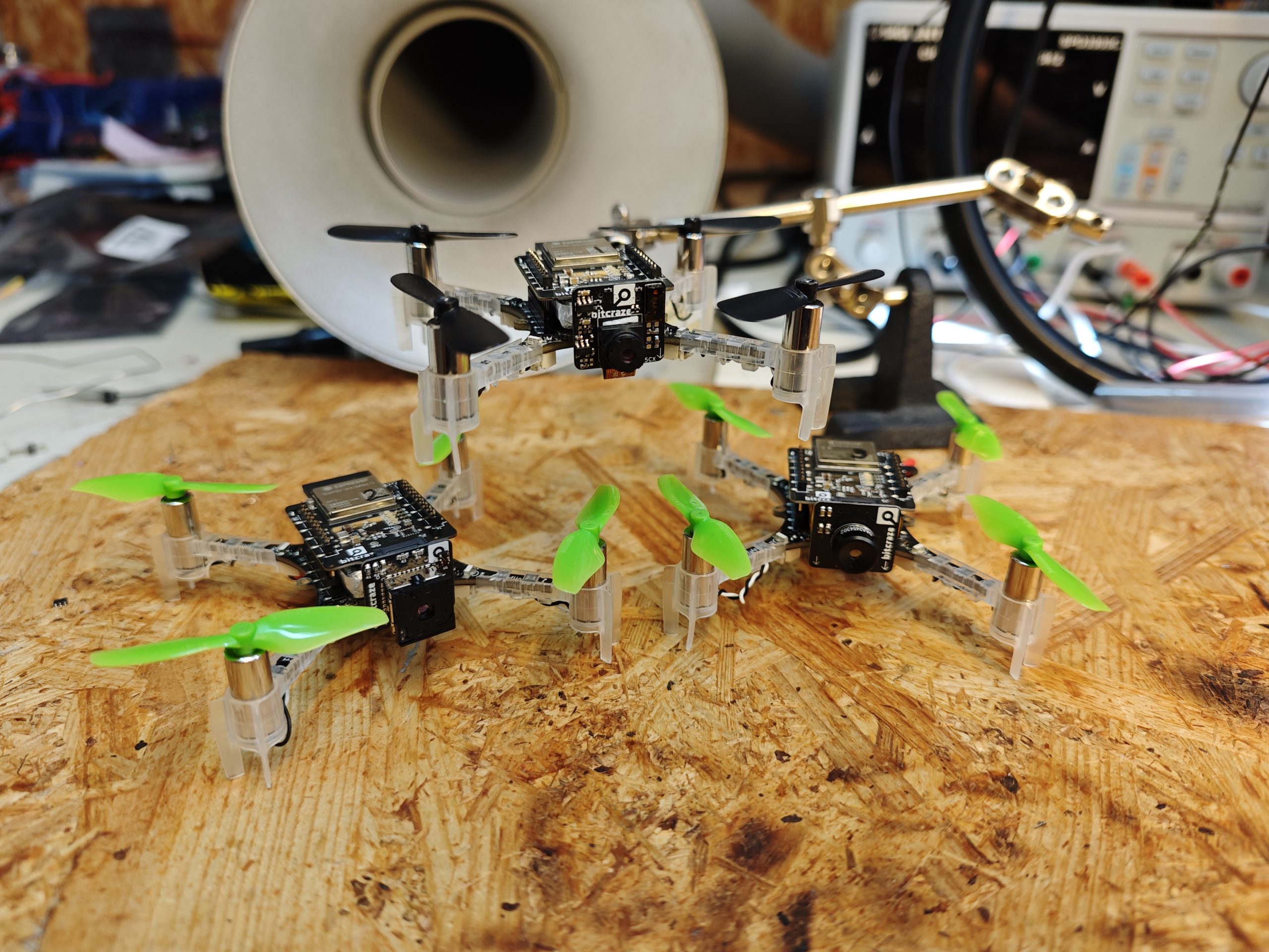
This deck has been designed to run a firmware developed by Said Alvarado-Marin from the AIO team at Inria in Paris. This firmware is able to acquire, decode and identify the FM1-encoded LFSR data stream we get from the base stations without the help of an FPGA or a big look-up table. This allows to greatly simplify the hardware and software by using only one microcontroller on the deck.
We are currently bringing-up the prototype and hope to be able to soon fly in our lab with 16 base stations. We will also be looking at making a standalone lighthouse receiver for other robots and applications. For the curious: the board under the deck in the picture in a debug board that contains everything we might need for making a standalone receiver plus everything needed to bring-up and debug the deck until we have it ready to fly.
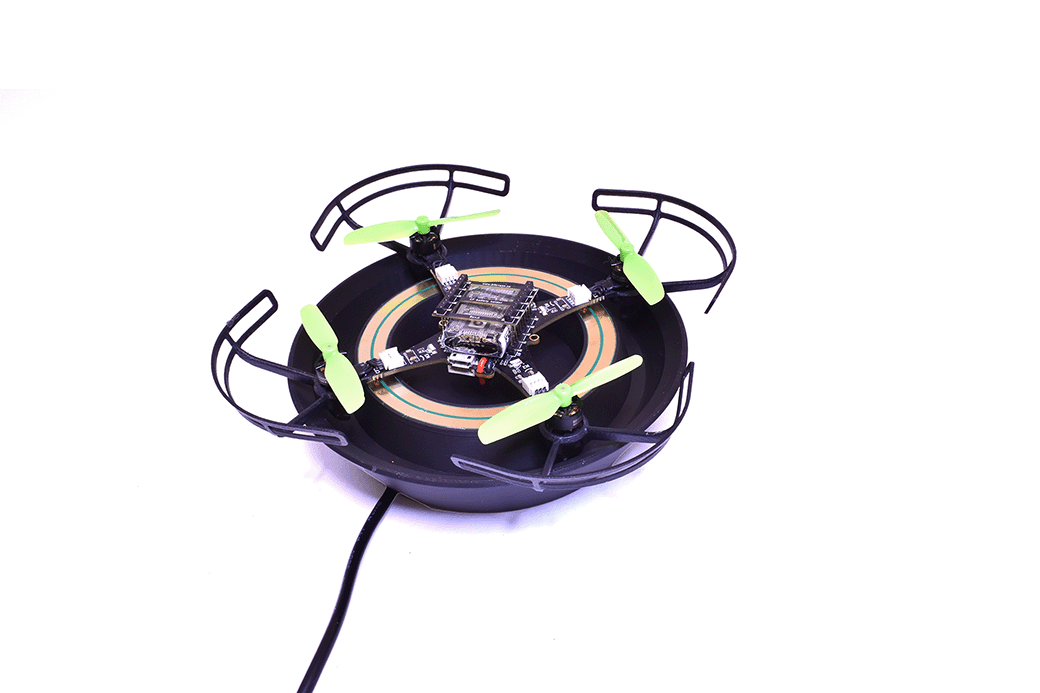
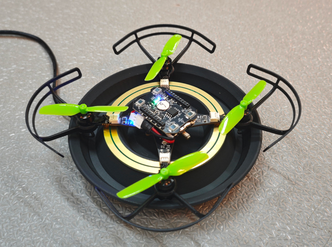
While planning for the Crazyflie 2.1 Brushless release we also decided to make our charging dock available to our users. We wanted our users to be able to make the same kind of demos we were making in our lab and showing off at fairs. To make this happen our 3D printer has been working around the clock the last couple of weeks, churning out as many charging docks as possible. And now we’re finally ready to put some in stock ? So make sure to check out the Charging dock in the E-store if you want to keep your Crazyflie 2.1 Bushless ready to fly at all times!
The charging dock is the same version we use in our flight lab, you might have spotted it in previous videos (like this one from last week). It’s also the dock we will be using our for swarming demos at fairs (like this one) in the future. Compared to the Qi deck, using this solution we save a lot of weight as well as maintain the possibility of having downwards-facing decks (like the Flow) mounted.
Although the main usage is for swarming (with autonomous takeoff/landing) you can also use it as just a charging dock, placing it here each time you’ve done some flying in the lab. This ensures that your Crazyflie is prepared for the next round of experiments.
If you’re interested in seeing a bit of history, have a look at some of our older blog posts about the charger. From the first prototypes, passed a fancy version with LEDs and WiFi and finally ended in the currently more sleek version we have today.
Ever since we started going to fairs to show off the Crazyflies, we’ve been trying to push the boundaries for the demos. Often we’ve used the fairs as an opportunity to either develop new functionality or try out new ideas. Something we’ve always been interested in, especially for fairs, is autonomous flights. It’s hard to talk to people about the Crazyflie while trying to fly it at the same time. Back in 2015 we were using the Kinect for piloting the Crazyflie at the Bay Area Maker Faire. Although awesome, we had a slight issue: we needed to switch batteries on the Crazyflie each flight. We had a Qi deck for wireless charging but no positioning system good enough to use it for landing on a charger.
Latest iteration of the Crazyflie Brushless charger
In 2018 we were really excited when we got to borrow a motion capture system from Qualisys and could finally land on a Qi charger (3D printed base and an IKEA Qi charger). First time we showed this off was at IROS in Madrid 2018. The following year we improved the demo to have more Crazyflies and switched to the Lighthouse positioning system at ICRA 2019. Since then each year we have been improving the demo until we’ve reached the current state we showed off at IROS 2022 in Kyoto.
So since 2018 we’ve been using the Qi wireless charging for our demos. Many customers have purchased the Qi charging deck, but building a matching charging platform has always required some effort. So, a while back we started looking at something that could replace the Qi deck, with a lighter solution which would also allow users to have other decks with electronics facing downwards. The first prototypes were made with the Crazyflie 2.1 back in 2021 using decks, but they were a bit clumsy. For one thing you needed the charging solution to be integrated on each deck.
When work started on the Crazyflie Brushless we realized we had the possibility to integrate the charge points directly on the main PCB which meant we could still use any decks we wanted and get the charging. So the prototypes from 2021 were reshaped into something we could use with the Crazyflie Brushless. Although the prototypes worked well, they were pretty big and packed with features which weren’t needed for charging (like LED lights and WiFi). Another iteration and the chargers have now gone down in size and complexity. The latest iteration only has charging and is powered via our 12V power block or 5V USB-C.
Over the years lots of customers have asked us for buying the Qi charger, since many users do not have the capabilities to build their own. Unfortunately we’ve never gotten around to it, but with the release of the Crazyflie Brushless we would like to change this. The release is only a few months away so we’re short on time for remaking the design so it’s usable for plastic molding. Instead the plan is to make a limited amount of prototypes available to our users, based on the same 3D printed design and electronics we’re currently using in our flight lab, at the time of release. This will enable our users to easily try out the design and create their own autonomous demos which will keep flying for a long time.
Whenever we show the Crazyflie at our booth at various robotics conferences (like the recent ICRA Yokohama), we sometimes get comments like ‘ahh that’s cute’ or ‘that’s a fun toy!’. Those who have been working with it for their research know differently, but it seems that the general robotics crowd needs a little bit more… convincing! Disregarding its size, the Crazyflie is a great tool that enables users to do many awesome things in various areas of robotics, such as swarm robotics and autonomy, for both research and education.
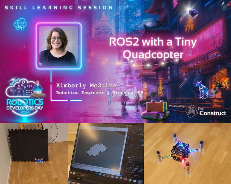
We will be showing that off by giving a live tutorial and demonstration at the Robotics Developer Day 2024, which is organized by The Construct and will take place this Friday, 5th of July. We have a discount code for you to use if you want to get a ticket; scroll down for details. The code can be used until 12 am midnight (CEST) on the 2nd of July.
The Construct and Robotics Developer Day 2024
So a bit of background information: The Construct is an online platform that offers various courses and curriculums to teach robotics and ROS to their users. Along with that, they also organize all kinds of live training sessions and events like the Robotics Developer Day and the ROS Awards. Unfortunately, the deadline for voting in the latter has passed, but hopefully in the future, the Crazyflie might get an award of its own!
What stands out about the platform is its implementation of web-based virtual machines, called ‘ROSJects,’ where ROS and everything needed for it is already set up from the start. Anyone who has worked with ROS(2) before knows that it can be a pain to switch between different versions of ROS and Gazebo, so this feature allows users to keep those projects separate. For the ROS Developer Day, there will be about five live skill-learning sessions where a ROSject is already preconfigured and set up for the attendees, enabling them to try the tutorial simultaneously as the teacher or speaker explains the framework.
Skill learning session with the Crazyflie
One of the earlier mentioned skill learning sessions is, of course, one with the Crazyflie! The title is “ROS 2 with a Tiny Quadcopter,” and it is currently planned to be the first skill learning session of the event, scheduled at 15:15 (3:15 pm) CEST. The talk will emphasize the use of simulation in the development process with aerial robotics and iterating between the real platform and the simulated one. We will demonstrate this with a Crazyflie 2.1 equipped with a Lighthouse deck and a Multi-ranger deck. Moreover, it will also use a Qi-charging deck on a charging platform while it patiently waits for its turn :D
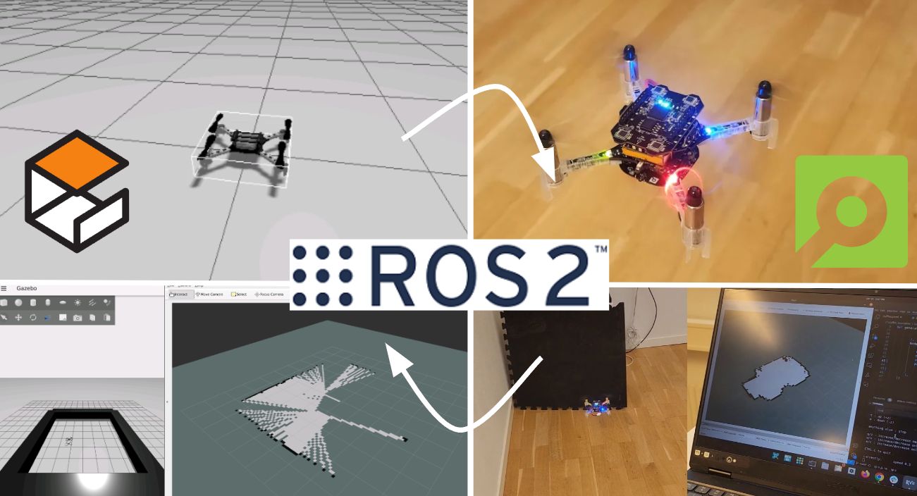
What we will be showing is a simple implementation of a mapping algorithm made specifically for the Crazyflie’s Multiranger deck, which we have demonstrated before at ROSCon Kyoto and in the Crazyswarm2 tutorials. What is especially different this time is that we are using Gazebo for the simulation parts, which required some skill learning on our side as we have been used to Webots over the last couple of years (see our tutorial for that). You can find the files for the simulation part in this repository, but we do advise you to follow the session first.
You can, if you want, follow along with the tutorial using a Crazyflie yourself. If you have a Crazyflie, Crazyradio, and a positioning deck (preferably Lighthouse positioning, but a Flowdeck would work as well), you can try out the real-platform part of this tutorial. You will need to install Crazyswarm2 on a separate Ubuntu machine and add a robot in your ROSject as preparation. However, this is entirely optional, and it might distract you from the cool demos we are planning to show, so perhaps you can try this as a recap after the actual skill learning session ;).
Here is a teaser of what the final stage of the tutorial will look like:
Win a lighthouse explorer bundle and a Hands-On Pass discount
We are also sponsors of the event and have agreed with The Construct to award one of the participants a Crazyflie if they win any contest. Specifically, we will be awarding a Lighthouse Explorer bundle, with a Qi deck and a custom-made charging pad similar to the ones we show at fairs like ICRA this year. So make sure to participate in the contests during the day for a chance to win this or any of the other prizes they have!
It is possible to follow the event for free, but if you’d like to participate with the ROSjects, you’ll need to get a hands-on pass. If you haven’t yet gotten a hands-on ticket for the Robotics Developer Day, please use our 50% off discount code:
On a side note, we will be at the Robotics: Science and Systems Conference in Delft from July 15th to 19th, 2024—just about two weeks from now. We won’t have a booth as we usually do, but we will be co-organizing a half-day workshop titled Aerial Swarm Tools and Applications (more details on this website).
We will be organizing this workshop together with our collaborators at Crazyswarm2, as well as the developers of CrazyChoir and Aerostack2. We’re excited to showcase demos of these frameworks with a bunch of actual Crazyflies during the workshop, if the demo gods are on our side :D. We will also have great speakers, including: SiQi Zhou (TU Munich), Martin Saska (Czech Technical University), Sabine Hauert (University of Bristol), and Gábor Vásárhelyi (Collmot/Eötvös University).
A great feature of the Crazyflie is its ability to keep evolving, both by using software but also through hardware expansions. Hardware expansions allow us and our users to keep exploring new problems and doing new experiments, without having to change the flying base. Over the years lots of new decks have been released and we’ve seen lots of users building their own custom electronics and attaching it to their Crazyflies. Although very versatile, the current deck system is limited to up/downwards facing expansions. Adding electronics that face forward, like a camera, has been harder and has required additional mechanics. Over the last couple of months we’ve been experimenting with a new expansion connector aiming at solving this issue. The idea is to be able to add a new class of expansions facing forward. This week’s blog post and next week’s developer meeting are about these experiments.
Goals and design
We’re always trying to find ways to make our platform more versatile, making it easier to expand and to be used in new ways. So we’ve been looking for a new way to be able to expand the platform even more, this time with electronics facing forward instead of up/down. The goal is to easily be able to add things such as cameras, ranging sensors etc. Making a custom deck with custom mechanics for each sensor hasn’t been a good solution, it takes lots of time and it doesn’t enable our users to do their own custom electronics. Finding a generic solution is hard since we’re constrained both in space and in weight. We need a solution which is very small and light, each gram adding cuts into the flight time. The solution also needs a way to handle the data generated from cameras/sensors as well as possibly to stream it over a faster connection than the Crazyradio.
Our current prototype is made of two parts, a new deck with WiFi and more computational power as well as several smaller expansions which can be added to it. The expansions fit straight into a small right angle connector, making it easy to change boards. The current connector we’re testing has 30 positions, of which 6 is used for power and 1 for 1-wire, leaving 24 pins for signaling. The 1-wire works the same way as our current decks, additional added hardware is auto-detected at startup and can be used without recompiling or reconfiguration.
The current prototype uses an ESP32-S3 and weighs in at 3.7 grams. Added to this there are a number of expansions that we’re evaluating:
OV2640 + VL53L5CX: RGB camera and ranging sensor (1.6 grams)
Flir Lepton 3.5: Thermal camera (2.1 grams)
MLX90640: Thermal camera (2.0 grams)
So the current prototype with RGB camera (and ranging sensor) weights in at a total of 5.3 grams (0.9 grams more than the AI deck).
Current status and continuation
We’re currently experimenting with connectors, modules and dimensions. In the coming months we will try to get more flight time to test the solution and we’re hoping to get some feedback from our users. So please post any comments and/or suggestions you might have.
If you’re interested in knowing more and discussing this then join our developer meeting next week on Wednesday. We will also be showing off the prototypes at ICRA, so make sure to swing by the booth if you’re attending.
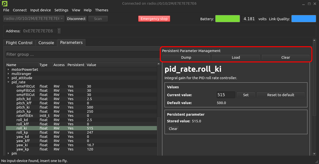
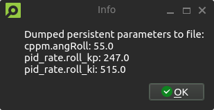
Dumping and loading persistent parameters to and from a file
We have a small quality-of-life update that will allow users to dump and load persistent parameters to and from a file that has recently been merged #PR443 and #PR706. A new persistent parameter management area is introduced to the parameters tab of the client, with buttons for dumping and loading persistent parameters, as well as clearing all stored persistent parameters from the Crazyflie. The persistent parameters are stored in .yml format, allowing for manual editing if desired. If you have any improvement suggestions please drop us a comment!
A new persistent parameter management area is introduced to the parameters tab of the client, with buttons for dumping, loading and clearing stored persistent parameters.An information dialog notifies users of the dumped persistent parameters and their values. Loading parameters will result in a similar pop-up.A confirmation dialog prevents accidental clearing of persistent parameters.
System-id code merged to master
Back in 2021, we created the system-id deck which we talked about in this blog post. It has not been officially released but a few users have gotten some PCBs and built it themselves. The functionality for the system-id deck has previously been in a branch, but as code in branches tends to become outdated, we have now moved this into the master branch utilizing the kbuild system instead. Building for the system-id deck is now as easy as doing “make sysid_defconfig” and then compiling. While talking about the system-id deck, let’s check the interest of releasing it as a product. It can help with system identification, tuning of controllers, improving efficiency etc. With enough interest there might be an economy in manufacturing it.
Out of stock
Unfortunately, we’re out of stock of Crazyflies at the moment. We expect some at the end of next week, so hopefully, you should be able to find them back in the store quickly.
Developer meeting
The next developer meeting will be on the 6th of March 2024, Arnaud will talk about the Crazyflie Client past, present and future, based on its last blog post. The client is still very useful but starts to show its age so we are looking at what should be kept, what should be improved and what should be removed. We will present what we have in mind, please come and discuss with us so we can shape the next 10 years of Crazyflie client!
If you haven’t seen it yet then check out our latest Christmas video! In it, we show off a bunch of new stuff, with the main ones being the new Crazyflie brushless and the Lighthouse V2 (which supports up to 16 base stations). But there were also a few other things featured in the video! One of them is the charging pad the Crazyflie brushless takes off from and lands on in the video. This weeks blog post is about the charger, how it came to be, how it works and what lies ahead.
Some history
A while back I worked a bit on a contact charger for the Crazyflie 2.1. The idea was to try and make a design where small pogo-pins could be added to various decks which would allow the Crazyflie 2.1 to charge when lading on a charging pad. Some of the issues with the design was that the area was small (it had to fit on a deck), it put requirements on each deck and that some decks (like the Flow V2 deck) has components which are taller than the pogo-pins. So after the blog post back in 2021 this has been on the shelf, until recently when the Crazyflie brushless work has been moving forward.
With the new prototype design for the Crazyflie brushless being made, there was a chance to address some of the issues I’ve seen before and do another try. All we needed was to add some pads for soldering pogo-pins on the wings (which actually wasn’t as easy as one would think due to layout constraints). So now the charging points didn’t have to be on each deck, they are built into the Crazyflie BL base. The distance between the points is also larger, allowing for a bigger hole in the charging PCB and allowing for a higher variety of decks, like the LED ring with the diffuser shown in the video.
The last missing part of the puzzle was when we needed to do more flight testing with the Crazyflie brushless. We wanted to reproduce the infinite flight demo we previously had for the Crazyflie 2.1, but the current Qi charger pad didn’t work with the new Crazyflie brushless. Time for the next iteration of the charger prototype!
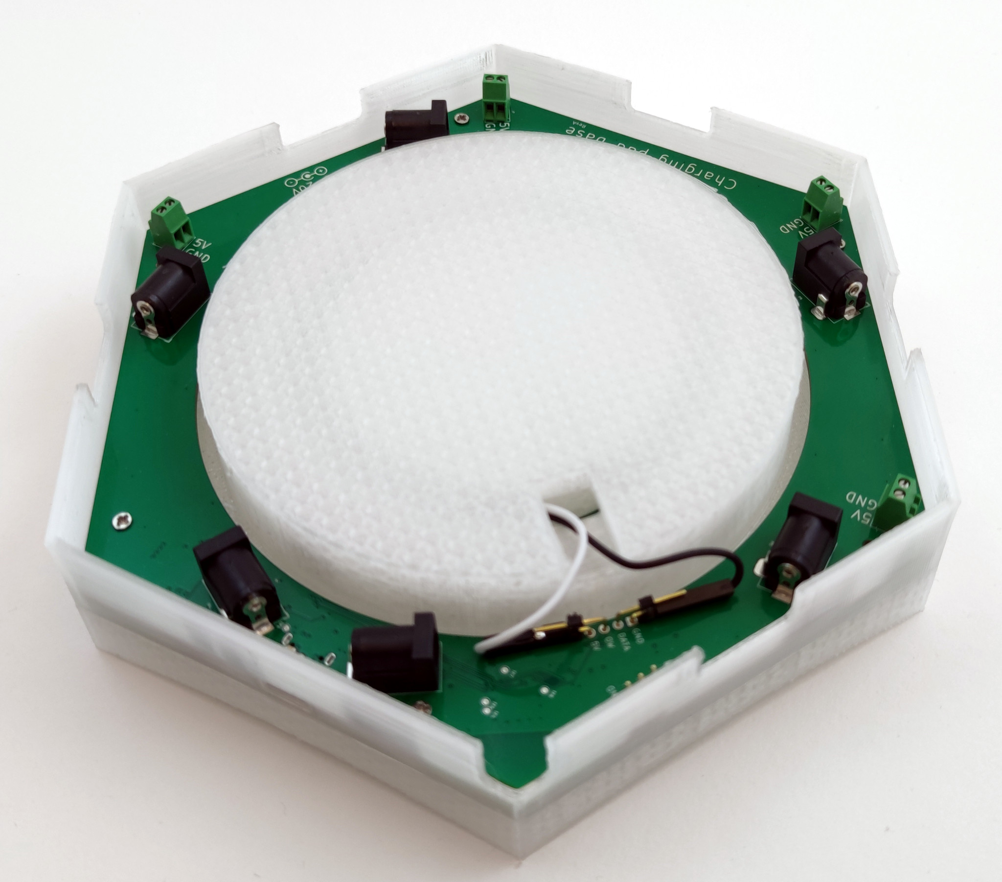
Under the hood
So how complex can you make a charger? Lots! When making a prototype I like to add as much ideas possible to the design. Missing something you wanted to test and doing a new version takes a lot of time but adding some extra crazy ideas might be pretty quick in the design phase. A lot of the time ideas are scrapped along the way, most of the time because of space- or price constraints. Sometimes they are just bad or too complex. Luckily in this case the charger has a large PCB with lots of space and it’s just an early prototype so there’s (almost) no bad ideas!
Under the hood (or 3D printed plastic in this case) there’s a bunch of stuff:
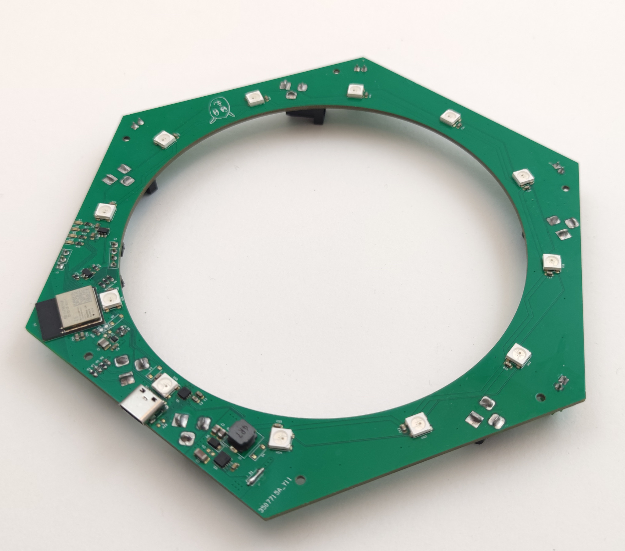
An WiFi/BLE module, the ESP32-C6-MINI
USB-C connector
USB-PD controller
6 DC-jack connectors and 5 terminals for connecting power
Measurement of charging current and supply voltage
12 WS2812B RGB LEDs for the outer ring and 12 for the inner one
20-to-5V DC/DC and 5-to-3V3 DC/DC
Some debugging LEDs and UART
Intended use
The idea with the contact charger has been to easily charge your Crazyflie without disconnecting the battery, plugging in the micro-USB connector or blocking the use of decks facing downwards like the Qi charger does. In addition to this I also wanted to try out some other ideas.
WiFi: For a long time I’ve had a prototype of a server for connecting various hardware to (like a charger) so I wanted to try to connect it to this for monitoring.
BLE: The idea was that the Crazyflie could talk to the charger via BLE to for instance change the light effect.
LEDs (and lots of them): The idea was to give some feedback from the charging of the Crazyflie but also to give the charger the ability to act as something more, like lighting up when a Crazyflie decides to land on it.
USB-PD: This is connected to the chaining of power. The ideas was to connect a USB-C charger and distribute the power from it to other chargers via the DC-jack.
Rust: Like we’ve written about before, we’ve been trying out more and more Rust here at Bitcraze. This is yet another experiment, the firmware for the charger is written in Rust using Embassy.
Future
Currently the charger is an internal project, since we use it in our lab for the infinite flight. But it’s of course something that would be exciting to offer our users if there any interest. So let us know what you think!
Also, don’t forget to join us for this Wednesday’s dev meeting. the main topic will be about the Kalman filters however we can answer questions about the wireless as well!
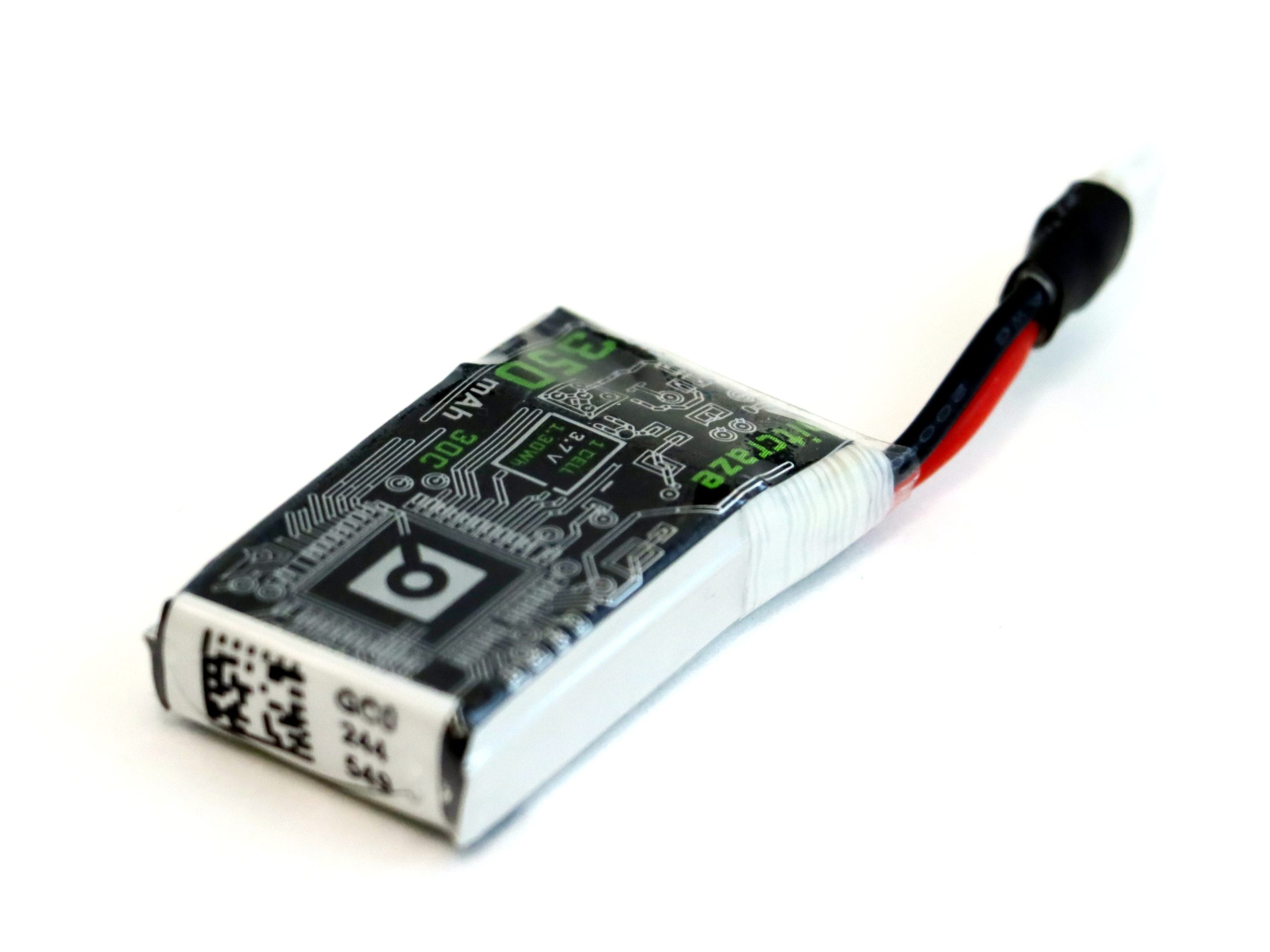
We are happy to announce that we are working on a new upgrade battery for the Crazyflies! It will soon hit production and hopefully, keeping our fingers crossed, it will arrive in our stock in early 2023-Q4.
The upgrade battery is based on the “Tattu 350mAh 3.7V 30C 1S1P” cell and with some additional great features:
Protection Circuit Module (PCM) to protect against short circuits, overcharge, over discharge etc.
Gold-plated connectors for lower contact resistance.
Shrink wrap around connector for better rigidity.
Cool Bitcraze matched graphics.
And if we list the benefits compared to the stock Crazyflie battery:
Higher current capabilities, 30C burst current, that is >10 Amp.
350mAh instead of 250mAh
Higher energy density, ~130 Wh/kg instead of ~105 Wh/kg
There are some drawbacks too:
It is ~1 mm thicker and does not fit well with all deck boards and the short or medium size pin headers. We will release longer pin headers at the same time though.
Price will be higher
~1.5 grams extra weight
With this upgrade battery, you will experience longer flight times, more “punch” during acceleration and it is great combined with the thrust upgrade kit!
As some of you may know, I’ve worked at Bitcraze for two summers (2019, 2020), and I did my Bachelor’s thesis here during the spring this year. While we mentioned shortly that I started working on my thesis (here), I never presented the results of it, so I thought that I’d do that now! Better late than never, right?
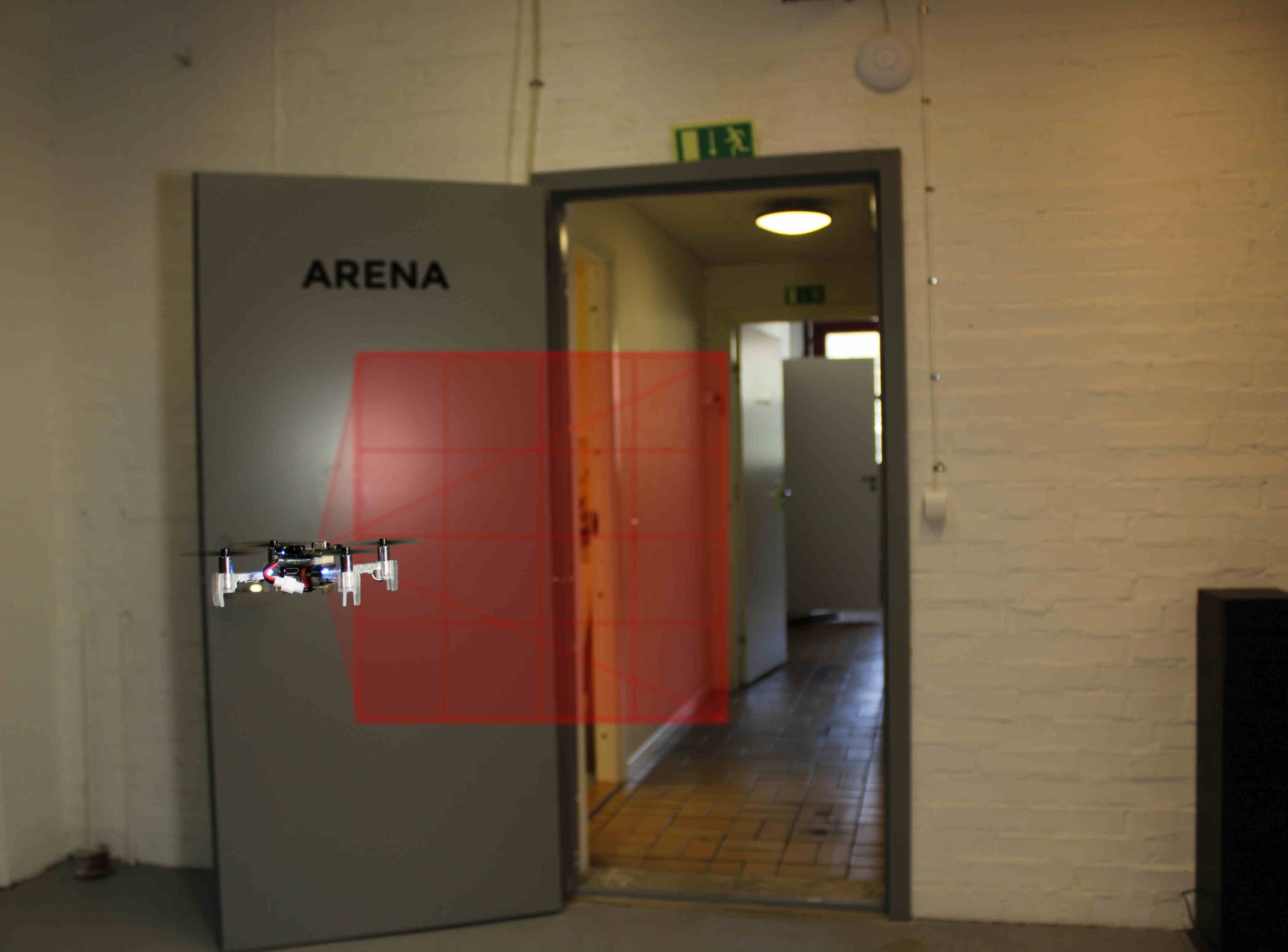
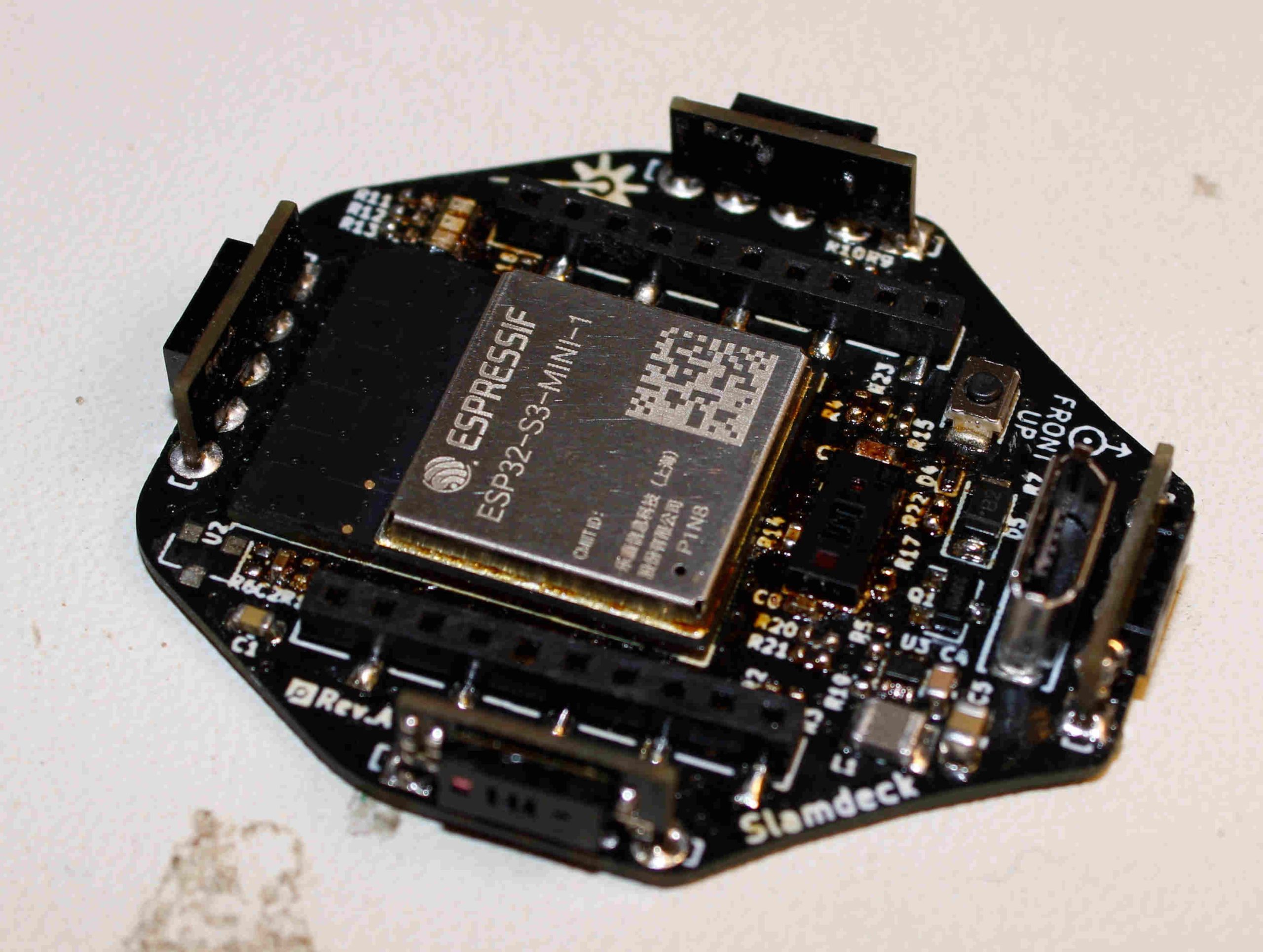
So, during my thesis I built a prototype deck for the Crazyflie which contained five multizone lidar sensors (VL53L5CX) and an ESP32-S3. The VL53L5CX sensors can output distances to a 8×8 grid, with a 45 degrees FoV at a rate of 15 hz. The purpose of the ESP32-S3 was to collect the data from the sensors and send it to a ground control station, either with WiFi, or, with the nRF radio on the Crazyflie. While the ESP32-S3 is quite overkill for only collecting data and send it, we weren’t sure of how much data that would be gathered from the sensors, so to be on the safe side we rolled with the ESP32-S3. Both the sensors and the microcontroller was very new at the time so it seemed like a good oportunity to try them out.
I designed the schematic in KiCad and got a lot of help from everyone here at Bitcraze while doing so, especially Tobias. Once the schematic was done I designed the PCB, ordered the components and then waited eagerly for the stuff to arrive. Once everything had arrived, I soldered all components and assembled the deck. I then wrote some firmware for the ESP32-S3, and the STM32 on the Crazyflie, and at last I wrote a simple GUI in PyQt to help visualize the data, both in 2D and 3D.
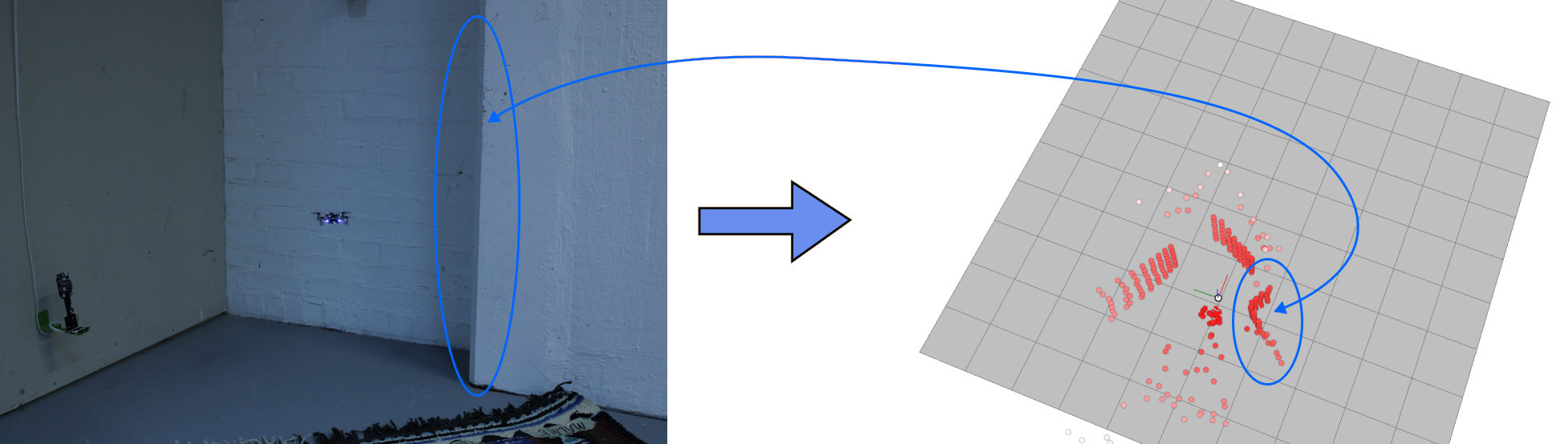
The deck was quite successful and while the GUI was very far from perfect, I think it did show that the deck has some nice potential and it was very cool to see the 3D point cloud in realtime while flying the Crazyflie! I tried sending the data over WiFi which worked perfectly well, and I also tried sending it through the nRF on the Crazyflie with the help of CPX, which also worked pretty well.
If you’re more curious about the thesis, feel free to check it out here, and the github repository can be found here.
I finished the thesis in the beginning of the summer, and I have been working part time here at Bitcraze since September and I’ve truly been loving! I think it’s been really cool to become a part of the team and work more on the regular stuff that the rest of the team does. It has been very interesting to see how the team works and cooperates on a daily basis. Something that striked me was just how many products and different features and services we handle here, with only six people!
Fortunately and unfortunately, I will be moving to Gothenburg next week which means that my time at Bitcraze is over, for this time. I have learned a lot from everyone here and truly appreciate all the love and support, which actually started before I even started my Bachelor’s degree.