Here at the USC ACT Lab we conduct research on coordinated multi-robot systems. One topic we are particularly interested in is coordinating teams consisting of multiple types of robots with different physical capabilities.
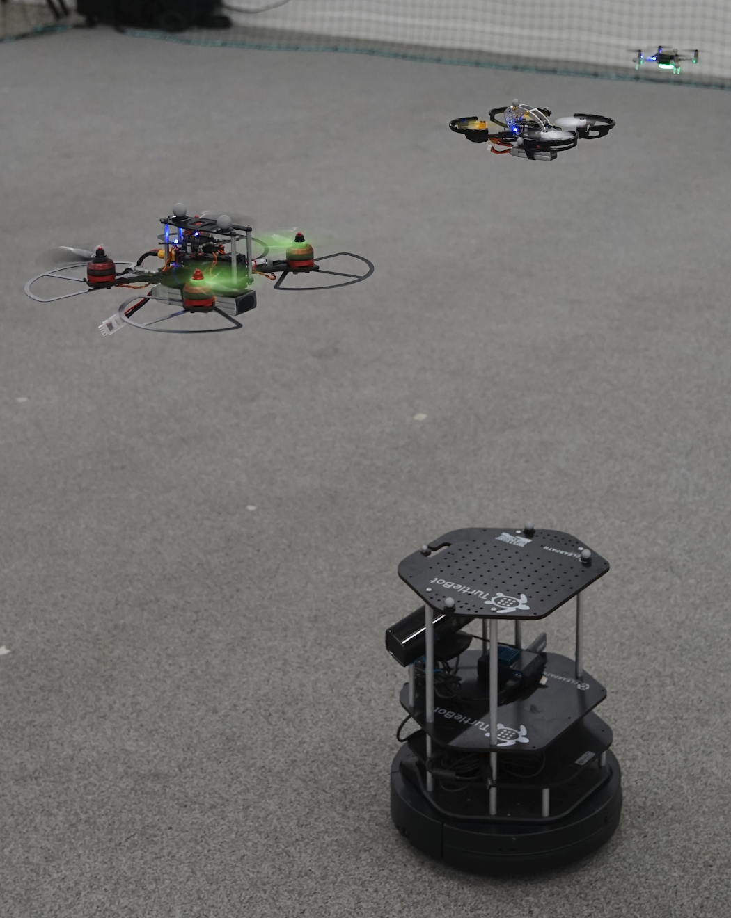
A team of three quadrotors all controlled with Crazyflie 2.0 and a Clearpath Turtlebot
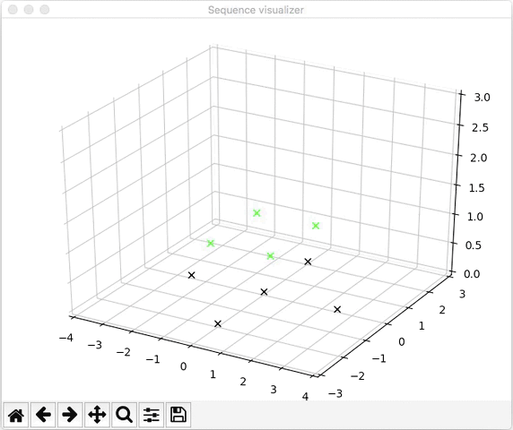
Applications such as search and rescue or mapping could benefit from such heterogeneous teams because they allow for more flexibility in the choice of sensors and locomotive capability. A core challenge for any multi-robot application is motion planning – all of the robots in the team need to make it to their target locations efficiently while avoiding collisions with each other and the environment. We have recently demonstrated a scalable method for trajectory planning for heterogeneous robot teams utilizing the Crazyflie 2.0 as the flight controller for our aerial robots.
A Crazier Swarm
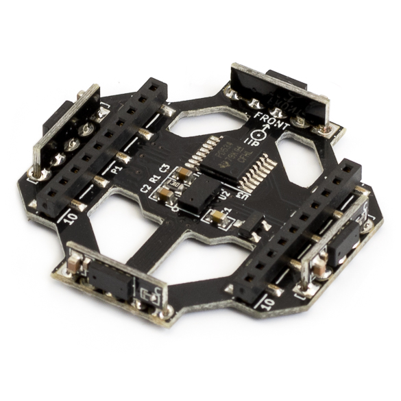
To test our trajectory planning research we wanted to assemble a team with both ground robots and multiple sizes of aerial robots. We additionally wanted to leverage our existing Crazyswarm software and experience with Crazyflie firmware to avoid some of the challenges of working with new hardware. Luckily for us the BigQuad deck offered a straightforward way to super-size the Crazyflie 2.0 and gave us the utility we needed.
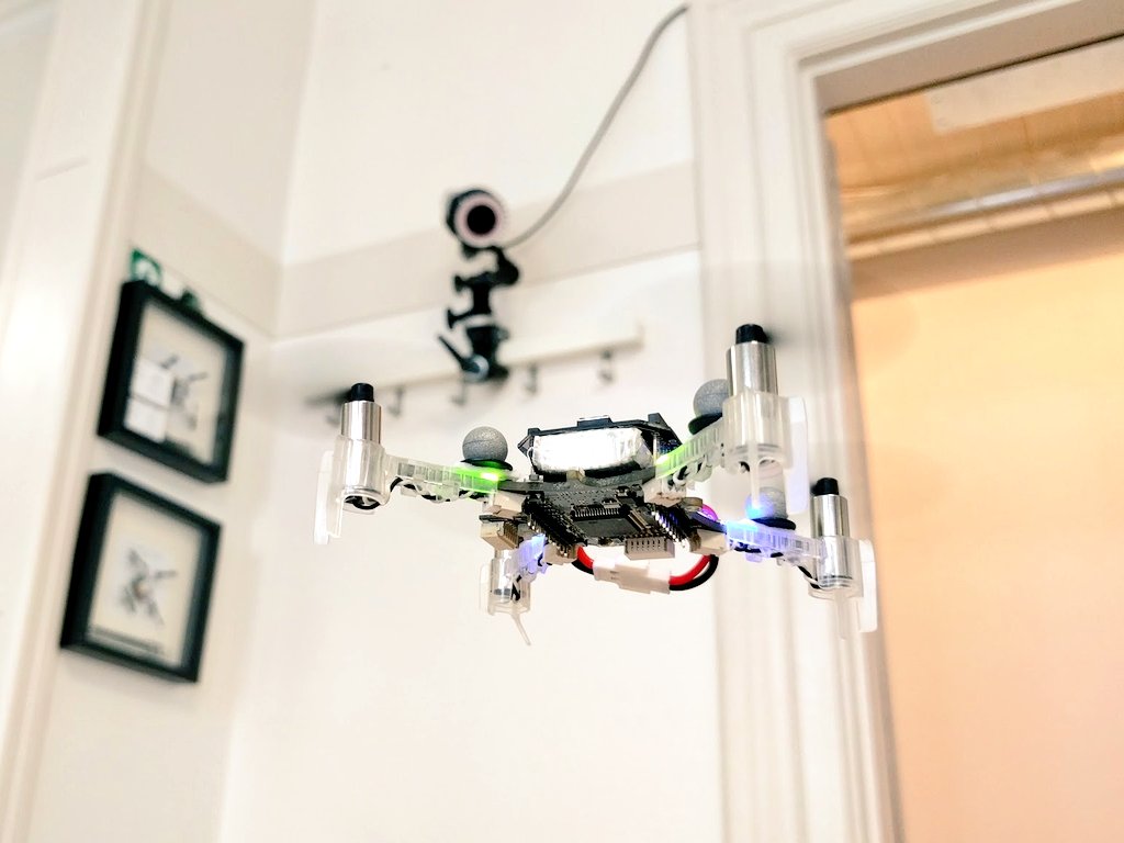
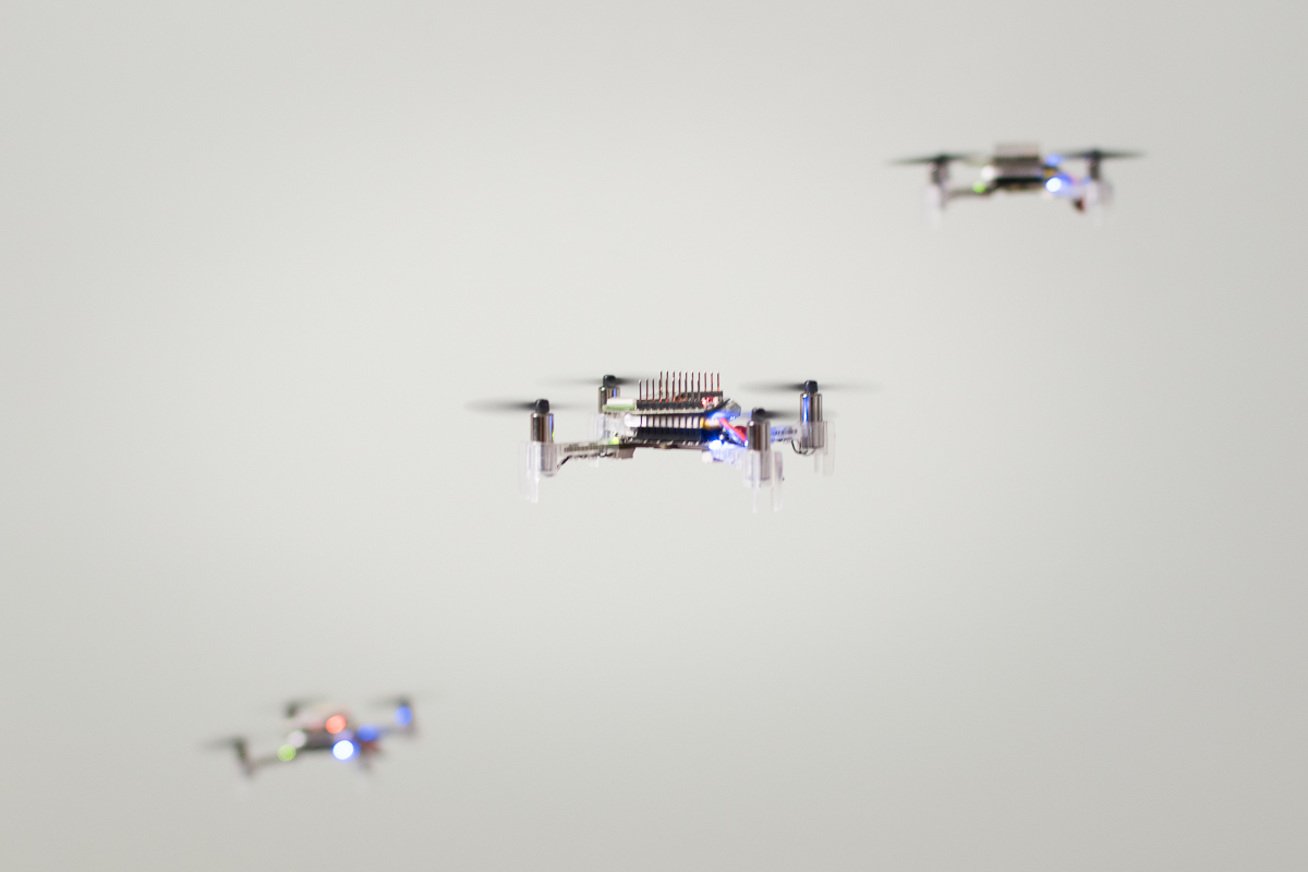
With the BigQuad deck and off-the-shelf components from the hobbyist drone community we built three super-sized Crazyflie 2.0s. Two of them weigh 120g (incl. battery) with a motor-to-motor size of 130mm, and the other is 490g (incl. battery and camera) with a size of 210mm.
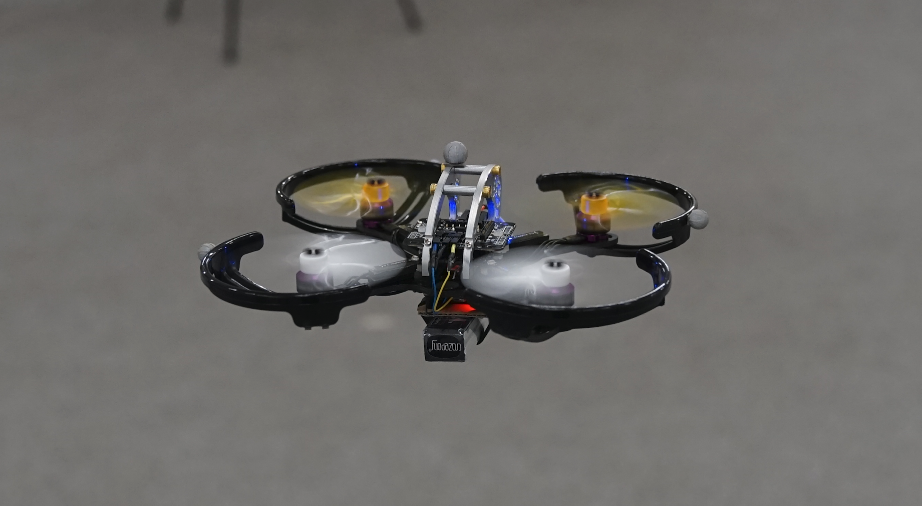
120g, 130mm
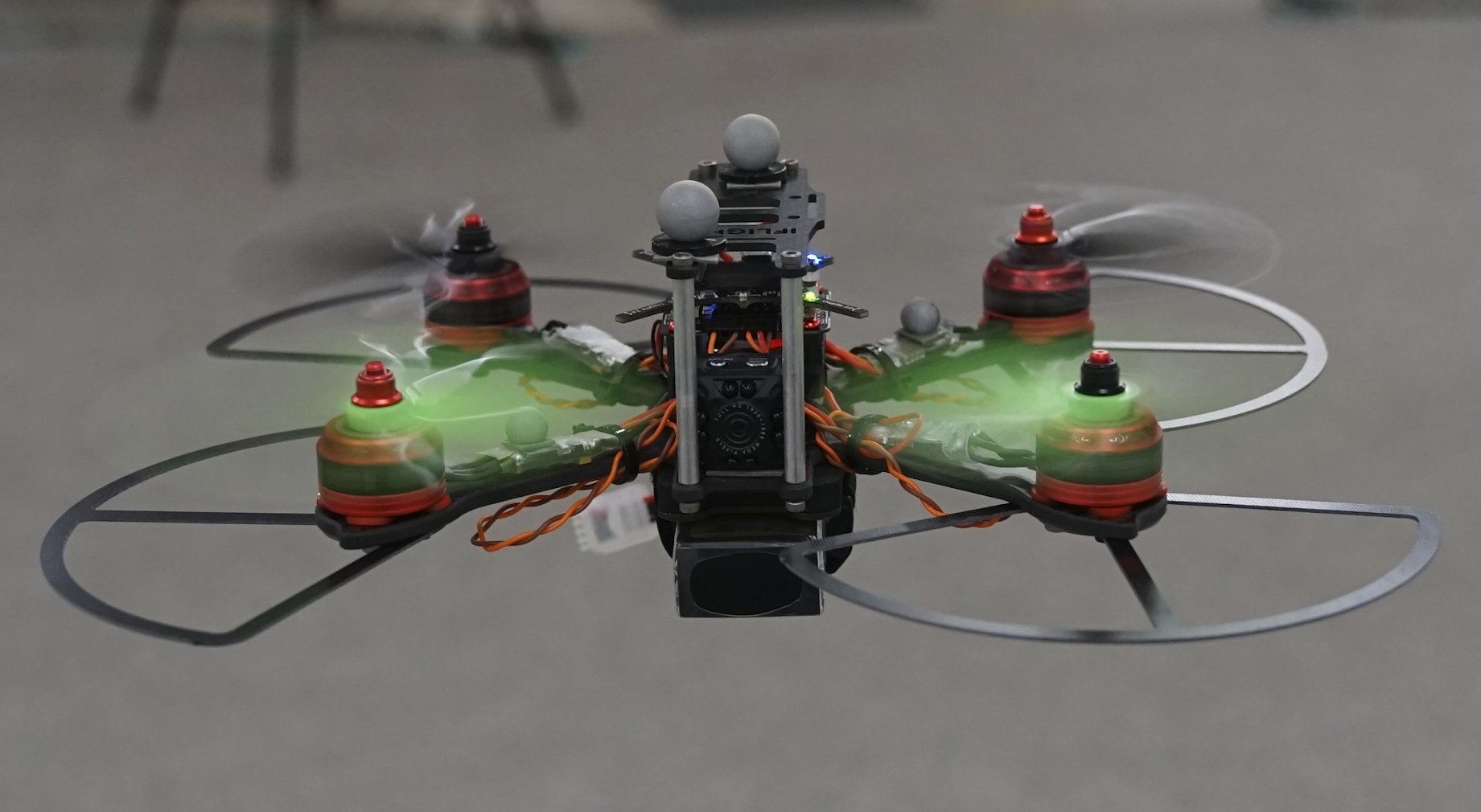
490g, 210mm
We wanted to pick components that would be resistant to crashing while still offering high performance. To meet these requirements we ended up picking components inspired by the FPV drone racing community where both reliable performance and high-impact crashes are expected. Full parts lists for both platforms are available here
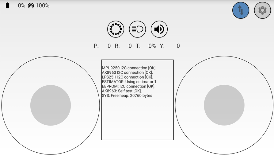
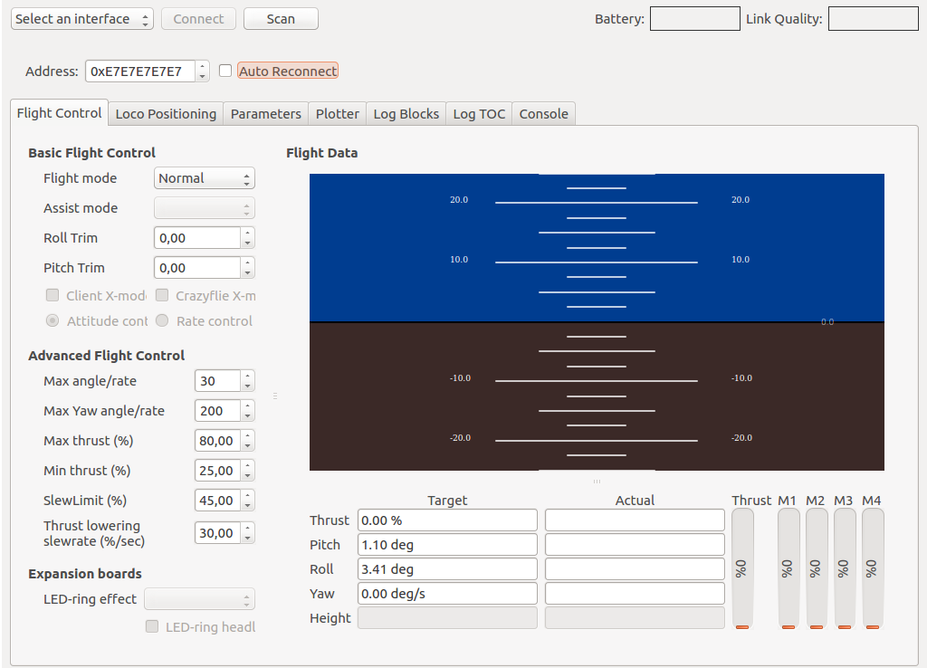
Integrating the new platforms into the Crazyswarm was fairly easy. We first had to re-tune the PID controller gains to account for the different dynamics of the larger platforms. This didn’t take too long, but we did crash a few times — luckily the components we chose were able to handle the crashes without any breakages. After tuning the platforms behave very well and are just as easy to work with as the original Crazyflie 2.0. We additionally updated the Crazyswarm package to be able to differentiate between BigQuad and regular Crazyflie types and those updates are now available for use by anyone!
In future work, we are excited to do hands-on experiments with a prototype of the CF-RZR. This new board seems like a promising upgrade to the CF 2.0 + BQD combination as it has upgraded components, an external antenna, and a standardized form factor. Hopefully we will see the CF-RZR as part of the Crazyswarm in the near future!
| Mark Debord Master’s Student Automatic Coordination of Teams Laboratory University of Southern California |
Wolfgang Hönig PhD Student Automatic Coordination of Teams Laboratory University of Southern California |